Step one of any good design is to communicate the core idea, both to yourself and others. Let's get into it a bit with the LIDAR Compass idea!
The Concept
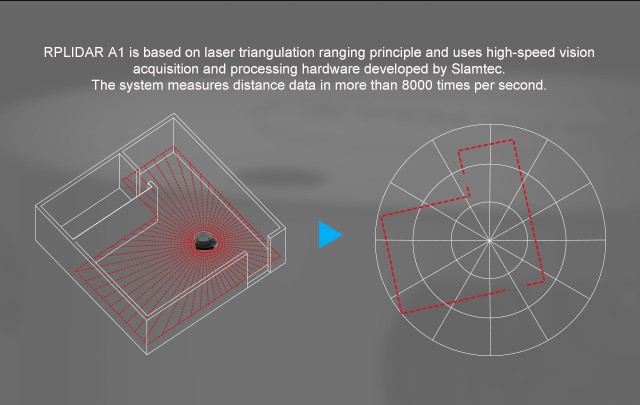
The main idea of the LIDAR Compass is to pair an ultra-low-cost 2D LIDAR (a lidar which spins in a circle ranging at every angle it passes through) with a visible laser emitter to create a sort of inside-out profilometer. You program a cross-section into the device running the LIDAR, and it measures the distance from itself to every point on that cross-section. For instance, imagine that the lidar is scanning a circle in a plane parallel to the ground, in the center of a room like in the SLAMTEC marketing image below:

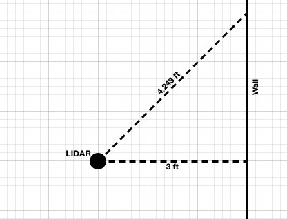
If the LIDAR is 3 feet from the wall directly to its right, and if we call "looking directly right" 0° angle, then we'd expect to see "range = 3ft" at angle 0°. The image above shows the LIDAR reference angle slightly tilted to the actual room angle, but let's assume they're aligned. Now, if the laser turns 45° to take its next sample, and if it's still looking at the same wall, by my math the wall should be 4.234ft away.

Now, let's turn this idea on its head, and consider the case where we want to MAKE a straight wall, maybe by putting framing studs in a straight line. We start by putting a stud at the bottom-right corner of that triangle, where the LIDAR shows 3ft. If we put one at the top-right corner and the LIDAR shows 4.234ft, we know the two studs are in a neat line, tangent to the LIDAR's 0° reference. If the second stud measures LESS than 4.234ft, we know the wall is going to be tilted. If we repeat for every stud on the wall, and if the LIDAR says the range to each is correct per the model, we know they're all in a neat row!
Of course, making straight walls is a silly example - we can easily make straight things, since we've got lots of tools built around the concept of straight-line measurements. Indeed, a chalk line and two measurements of the tape measure could accomplish the task above.
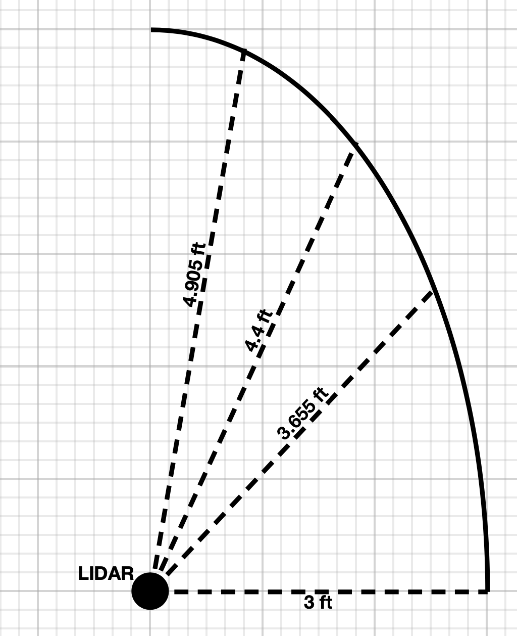
But what if we want to precisely make an arbitrary curve instead of a straight line? Using rulers and straight lines can get you straight walls, and if your clever, a straight line can also get you a perfectly circular radius. Beyond circles, though, the measurement task starts to get tricky and error prone.

Of course, the LIDAR doesn't have any trouble with that. All it does is measure the range to an object at any given angle. All we have to do is give it a table of angles and ranges, and it can tell us whether reality matches the table.
But it doesn't do us much good to build a whole dome, then measure it after we're done only to find out we built it wrong. The tool has to be able to tell us IN REAL TIME whether we're doing the "right" thing.
The second half of this equation is a laser EMITTER, paired with the measurement, that can show whether the current construction matches the digital profile the device has been programmed with.
Take the case where the LIDAR angle is 0°, and the LIDAR measures a 3ft range to the wall we're building. In this case, the distance is "correct" per the model of what we're trying to build. The LIDAR Compass device signals this by using a second laser to paint a green line over this section of the circle. Fast forward to 90°, where the wall hasn't been built yet and the LIDAR either measures infinity, or just errors with "no return." Along this section of the circle, the green laser remains dark, to indicate that the wall isn't in the right spot.
In other words, as you're building the wall, anywhere the wall is in the right spot gets painted green. If there's a section that's not green, you know it's either too close or too far. If you haven't PLACED a section of wall yet and need to know where it goes, just stick a finger in the way: if it lights up green, you know you should place the material right where your finger is!
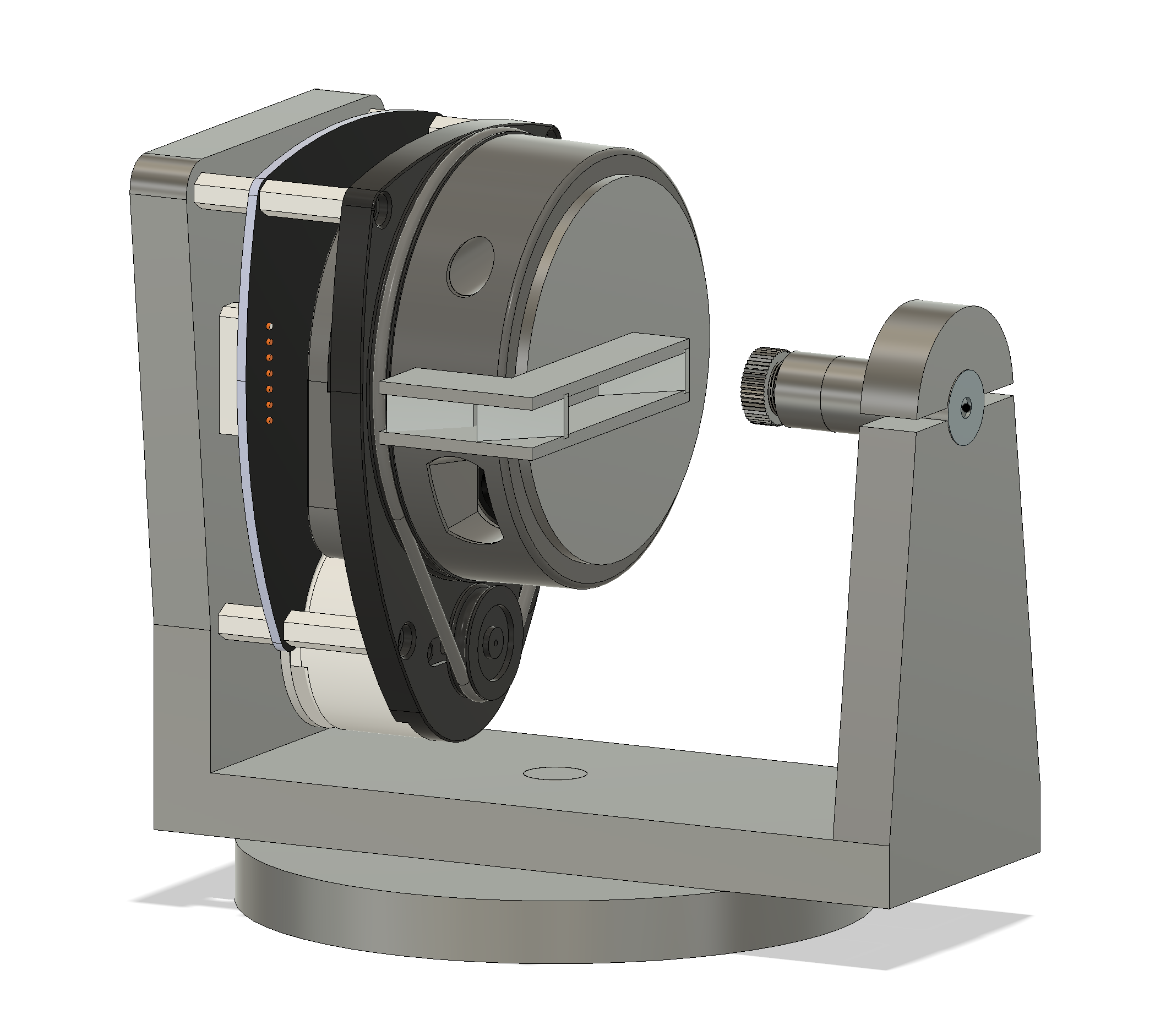
The final piece of the puzzle is to simply turn this on its side, and paint a vertical circle instead of a horizontal one. Thus, we get to see whether the cross section of a dome is correct, rather than the entirety of any given layer. If we take this one step farther and rotate the entire device slowly, we get both! Green, and the wall's in the right spot.
BONUS MATERIAL: behind the scenes

 alexwhittemore
Discussions
Become a Hackaday.io Member
Create an account to leave a comment. Already have an account? Log In.