 Justin Walsh
-
1Alarm LED
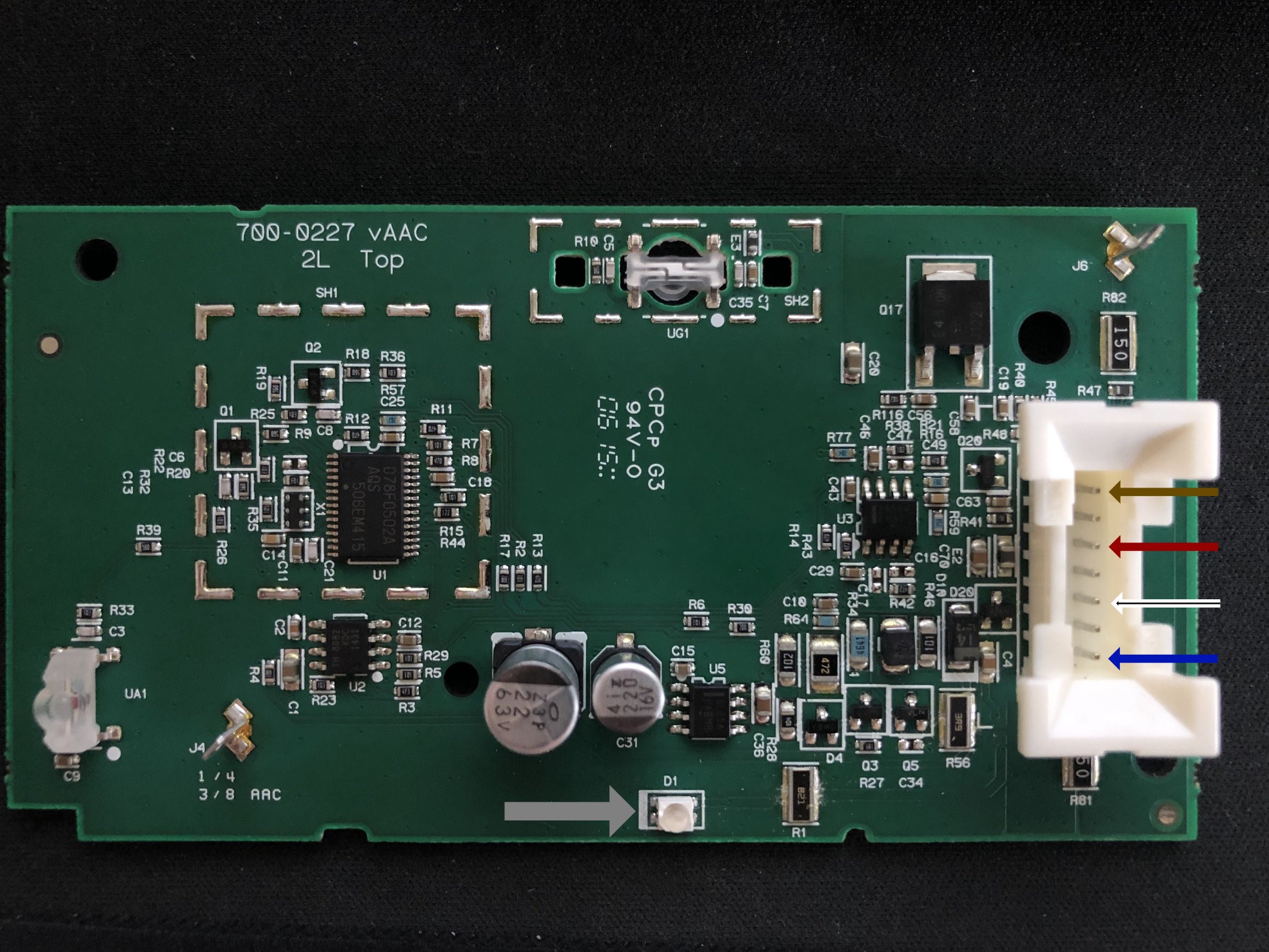
This circuit board that is included in the i3 mirror contains all the bits needed to make the OEM mirror dim. It also includes the LED (grey arrow) that will blink when locking the doors, and when the alarm is activated. I wanted to salvage the LED functionality, while ignoring anything else this circuit board wants to do.
![]()
From what I can tell the wires are as follows:
- Brown, Ground (-)
- Red, 12v Constant ACC
- White/Black Stripe, Reverse Signal Wire (did not test voltage)
- Blue, 12v LED (+) load applies intermittently for blinking.
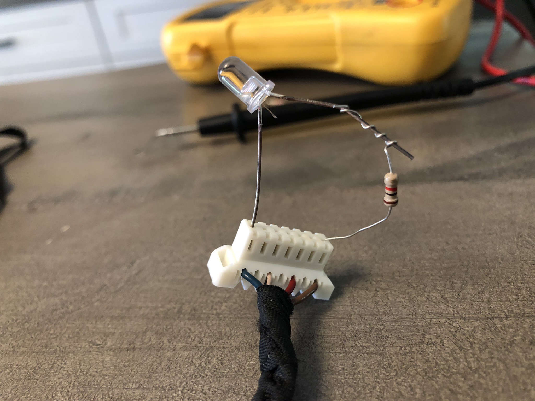
Testing the board with a multi-meter revealed that the LED is simply attached to a 821Ω resister, and the ground plane. To reconstruct this circuit, I simply soldered an 1kΩ resister to the cathode and connected to the brown wire, then connected the anode to the blue. Wrap it all up in some nice heat-shrink, and use some breadboard dupont male jumper wires so that we can just plug it into the factory connector.
![]()
When fully assembled, I added a bit of hot glue to stick the LED in the hole on the mount that fits the factory sensor light diffuser and snaps into the mount shell.
![]()
BMW i3 Dash Cam Mirror
A very specific project for mounting a very specific dash-cam mirror to the i3 mirror mount without strapping it on with rubber bands.

Discussions
Become a Hackaday.io Member
Create an account to leave a comment. Already have an account? Log In.