0%
0%
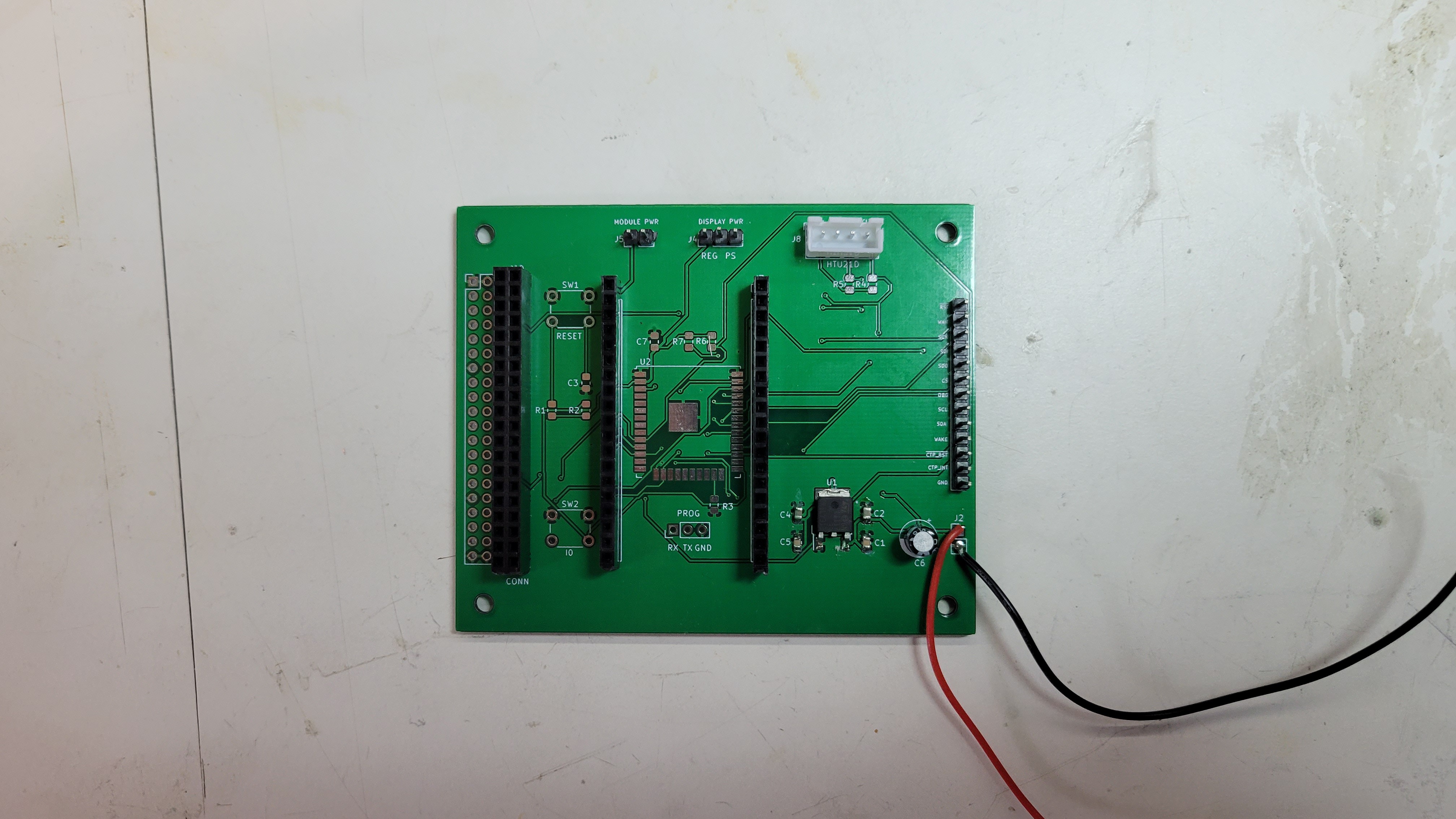
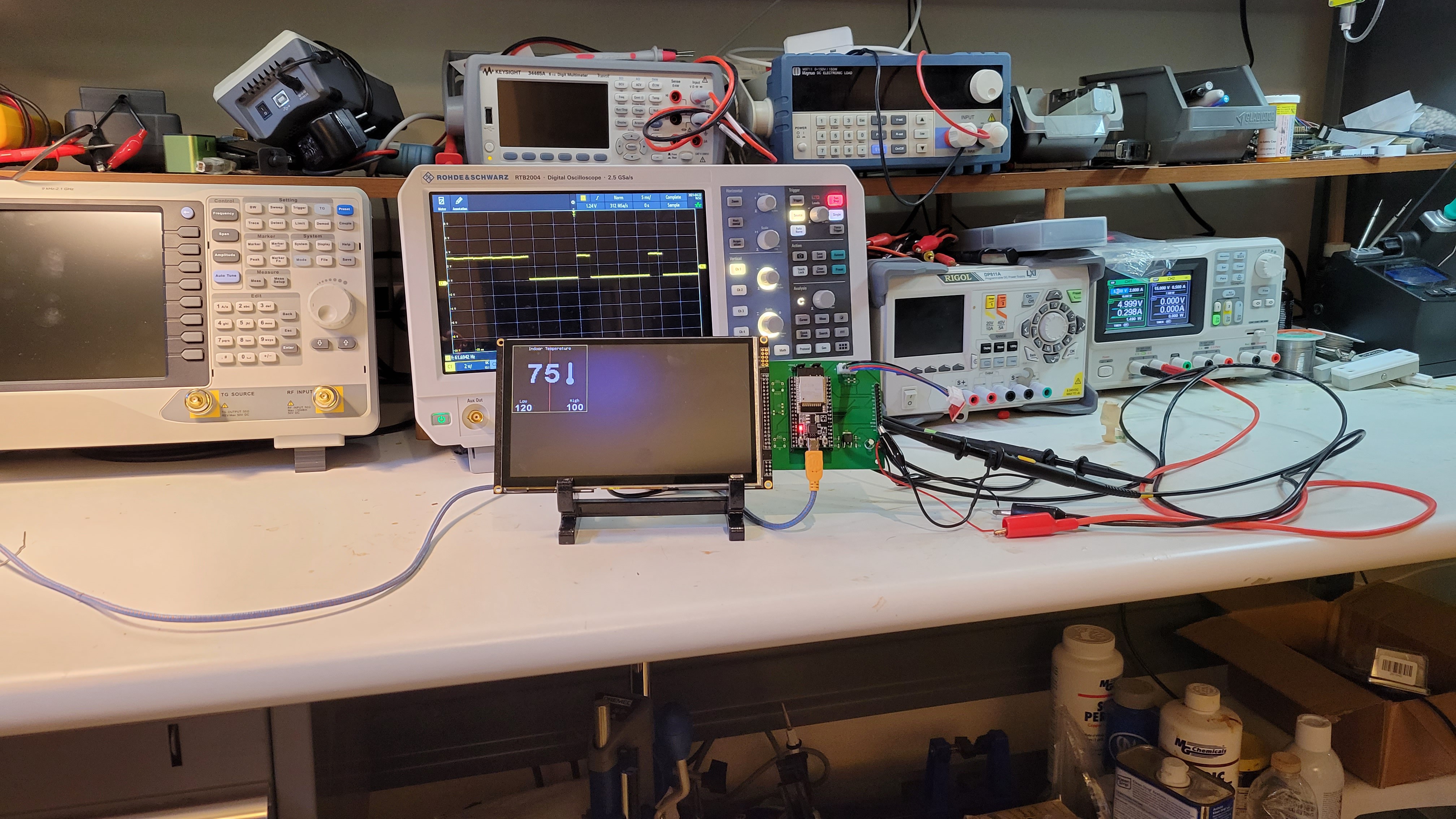
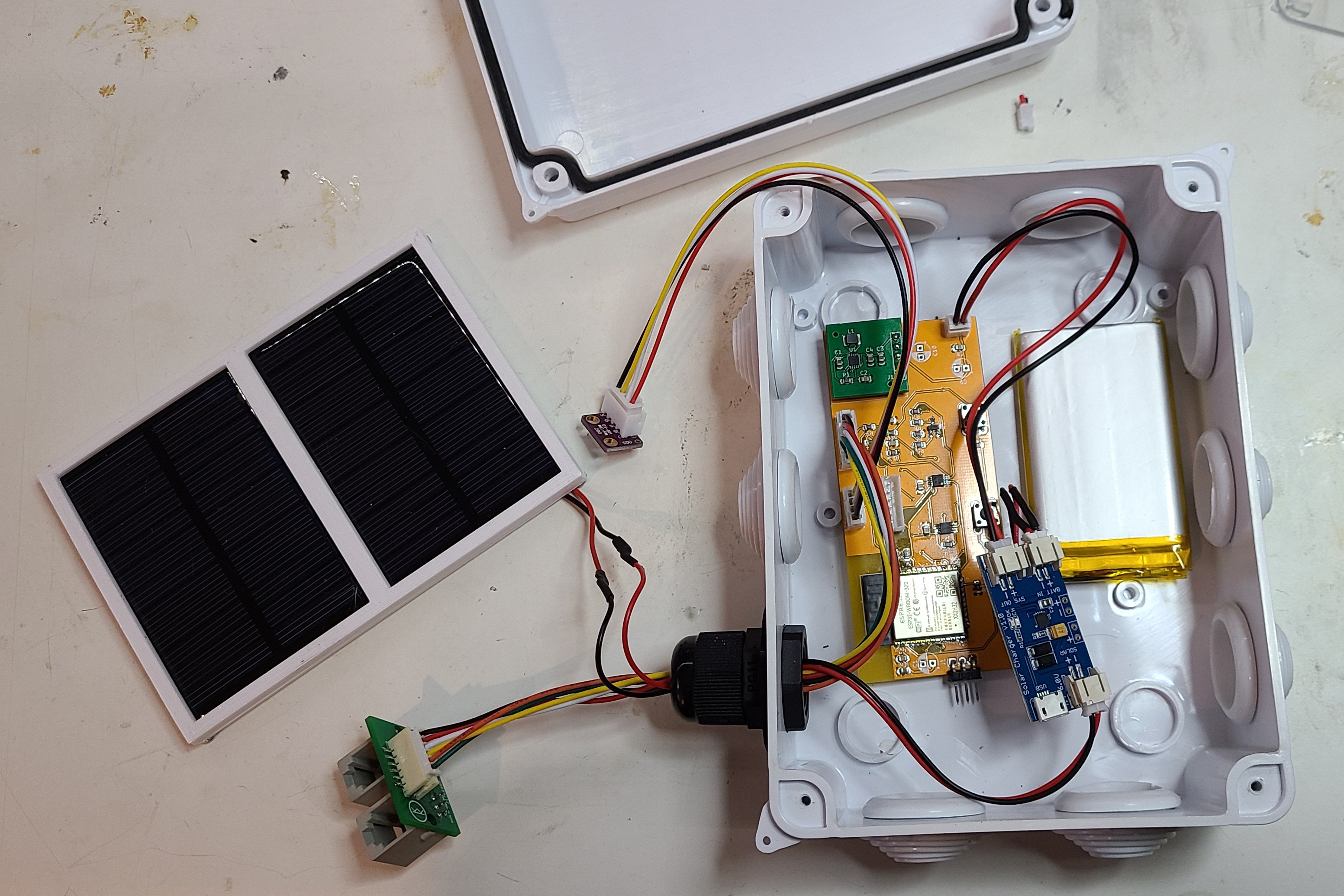
ESP-NOW Weather Station
An ESP32 based weather station investigating ESP32's Deep Sleep and ESP-NOW
 Kevin Kessler
Become a Hackaday.io member
Already have an account? Log in.
Just one more thing
To make the experience fit your profile, pick a username and tell us what interests you.
Pick an awesome username
hackaday.io/
Your profile's URL: hackaday.io/username. Max 25 alphanumeric characters.
Pick a few interests
Projects that share your interests
People that share your interests


 JP Gleyzes
 David M.
 Capt. Flatus O'Flaherty ☠
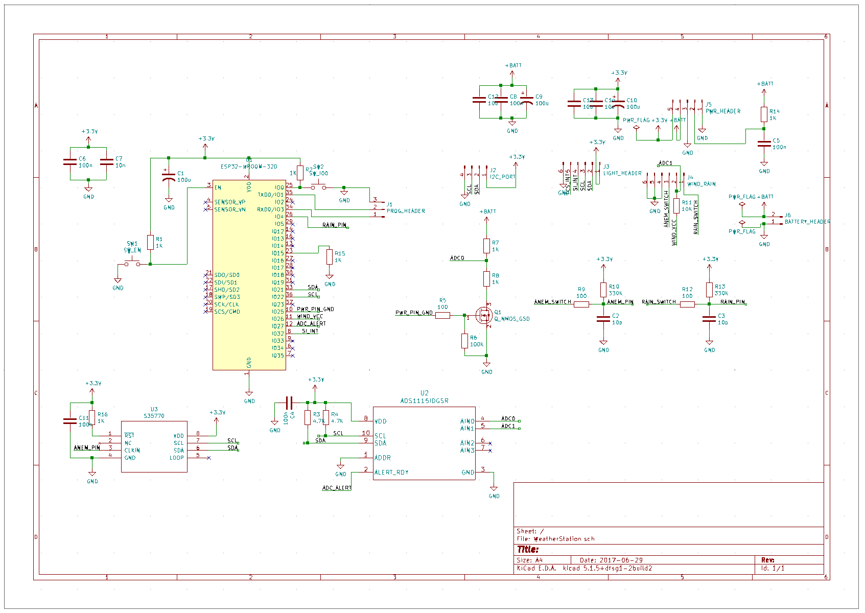
I'm looking to make a weather station with the same sensors and an ESP32 to send MQTT datas to my networks, your project looks interessant!
My only problem now is how to be sure to measure the good wind speed and rain quantity, can you say me how you do the count, for wind you have a timer and count the nomber of pulse of sensor ? and the same for the rain ? If yes what is your
values ?