Close
0%
0%

DIY Home Automation System

Home automation is a hot topic nowadays and even the simplest components of such a system can cost a lot. Therefore building custom devices

Similar projects worth following
Hii Friends Welcome Back 珞Today I'll Show You How To make Simple Home automation SystemSo Let's Make ItYou I'll Need Some Componenets For this1. Plastic Box2. Nodemcu3. Bulb Holder4. Wire5. Relay ModuleThanks for NextPCB sponsor this project. For New Customer, Your First Order Will Be Free. http://www.nextpcb.comNextPCB is a high-quality PCB Manufacturer in Shenzhen China. With professional PCB manufacturing capabilities, for each file of our customer will be double-checked by more than 10 years PCB engineers. PCB materials are certified by ISO9001, UL; We handle the whole process including PCB manufacturing, PCB assembly, testing, and final shipment. We are capable of assembling BGA, Micro-BGA, QFN and other leadless package parts. We also have an online parts shop, you can choose any parts if you needit.

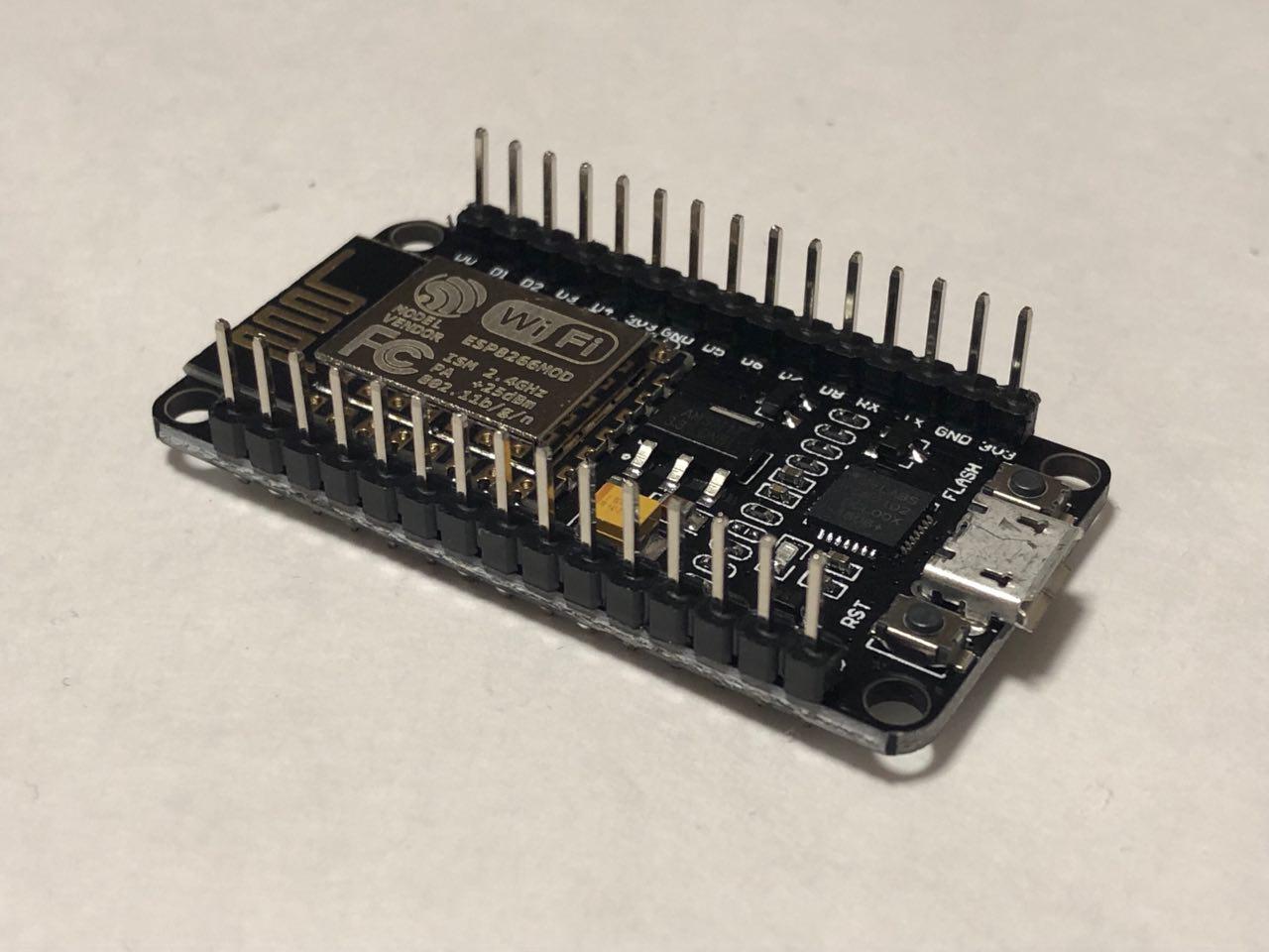
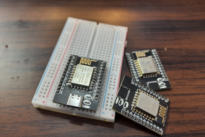
NodeMCU is very popular in Home Automation. It’s WiFi capabilities and Arduino IDE support making it easier for IoT Applications. It is very tiny and has many Digital I/O pins, Serial Communication and I2C Communication. NodeMCU has a micro USB port to program it using your existing mobile cable (no additional programmer needed). There is a successor called ESP32 Development board which has more Analog pins and Digital pins. You can use any one of them for this project according to your requirements. Here we will be using NodeMCU.

Blynk is a mobile application which has its own server to process user requests. It is an open source application and anybody can use it in their Home Automation to control devices, monitor sensor data and get a notification by some trigger actions. It has a nice GUI with Graphs, Timers, Slider, Joystick and even Video Streaming. You can also make your own app and publish it in Google play store.

Components required:

Hardware:

  • NodeMCU Development board – Buy Now
  • 4 Channel Relay – Buy Now
  • USB cable

Software required:

Circuit Diagram:

IOT Home Automation using Blynk and NodeMCU FactoryForward

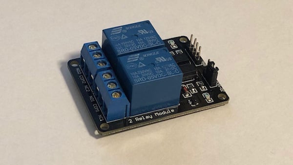
Note: For example purpose, we have connected Relay at D0, D1, D2 and D3. You need to make sure there should not be alternate functions to that pins. Because the D0 pin has connected with Onboard LED (D4 has TXD1 function), whenever you Power ON the NodeMCU it blinks for a second. In case you have connected a Tube Light, it will flash during startup. So please refer the NodeMCU pinout and assign the proper pins without any conflictions.


JPEG Image - 62.10 kB - 09/24/2020 at 17:34

Preview
Download

  • 1 × Nodemcu
  • 1 × Relay Power Supplies / Uninterruptible Power Supplies (UPS)
  • 1 × Box Frequency Control / Oscillators
  • 1 × Jumper cables

  • 1
    Step 1

    The Hardware

    The main component of this build is a simple relay board that can be used to switch voltages up to 250V AC and a maximum current of 10 amperes:

    simple relay board

    A simple relay board for higher voltage projects.

    It’ll be controlled by an ESP8266 based IoT developer board which is fully compatible with the Arduino IDE. Alternatively, you could also use a standard Arduino and an ESP8266 (or similar) breakout board.

    esp8266

    The ESP8266.

    You only need to make two connections between these devices. One of them is ground, the other is a control line for switching the relay which I chose to connect to D2 (digital pin two) of the developer board.

    The relay and the MCU need to be connected to a five-volt power supply which, in my case, is accomplished with a simple DC jack.

    Other than that, you’ll also need a standard mains socket, an IEC plug, preferably one with an earth pin, and a switch for turning the MCU ON and OFF. Furthermore, an enclosure is needed. I chose to go with a standard grey project box:

  • 2
    Code
    #include <ESP8266WiFi.h>
    
    #define RELAY_PIN D2
    
    const char* ssid = "YOUR_WIFI_NETWORK";
    const char* pass = "YOUR_NETWORKS_PASSWORD";
    
    WiFiServer server(80); void setup()
    {  Serial.begin(9600);
      // You could add an EEPROM to store the last state if the device gets powered off.  // See: https://maker.pro/arduino/tutorial/how-to-permanently-store-data-on-your-arduino  //  // It's also possible to store the website and stylesheets/additional scripts on an SD  // card and display the files to a client when they connect.  // See: https://maker.pro/arduino/tutorial/how-to-use-an-sd-card-with-your-arduino  //  // However, this simple example will always start with the relay turned on and a very  // basic HTML page with two buttons.    pinMode(RELAY_PIN, OUTPUT);  digitalWrite(RELAY_PIN, HIGH);
      // Connect to your local network  WiFi.begin(ssid, pass);   while (WiFi.status() != WL_CONNECTED)    delay(250);
      Serial.print("Connected to network: ");  Serial.println(ssid);   // Start the server  // A client will connect to this server to change the state of the relay  server.begin();  Serial.print("Server started with address: ");  Serial.print("http://");  Serial.print(WiFi.localIP());  Serial.println("/");
    } void loop()
    {  // Check for incoming connections  WiFiClient client = server.available();    if (!client)    return;   // Wait for the client to send data  while(!client.available())    delay(5);   // Read the first line of the HTTP request  // which will contain something like  // METHOD /requested_url HTTP_VERSION  // for example:  // PUT /dev2?relay=1&state=on HTTP/1.1  // However, for the sake of simplicity this device will  // respond to GET requests so that they can be sent with  // any web browser. Requests to this device will look  // similar to this:  // GET /state=on HTTP/1.1  String request = client.readStringUntil('\r');  client.flush();
      int state = 0, error = 0;    // Check, whether the request contains "/state="  if (request.indexOf("state=") != -1)  {    // HIGH and LOW are swapped in this program because my    // relay is turned on when its input pin is pulled LOW.    if(request.indexOf("state=on") != -1)    {      digitalWrite(RELAY_PIN, HIGH);      state = LOW;    }    else if (request.indexOf("state=off") != -1)    {      digitalWrite(RELAY_PIN, LOW);      state = HIGH;    }    else    {      error = 1;      Serial.print("Unknown request: ");      Serial.println(request);    }  }   // Return the response  // If no error occurred, send an HTML page with two buttons  // so that the device can be managed.  // Otherwise, send an error message  if(error == 0)  {    // Return a response header    client.println("HTTP/1.1 200 OK");    client.println("Content-Type: text/html");    // The HTTP response body is separated from the header by an empty line    // (actually a line containing \r\n, but this will work)    client.println("");
        // Return the response body (an html page)    client.println("<html>");    client.println("<head>");    client.println("<title>Simple home automation</title>");    client.println("</head>");    client.println("<body>");    client.print("The relay is turned ");    client.print(state==HIGH?"on":"off");    client.println("<br> <br>");    client.println("Change state:");    client.println("<a href=\"/state=on\"><button>Device on</button></a>");    client.println("<a href=\"/state=off\"><button>Device off</button></a>");      client.println("</body>");    client.println("</html>");  }  else  {    // Return a response header    client.println("HTTP/1.1 400 Bad Request");    client.println("Content-Type: text/html");    client.println("");    client.println("<html>");    client.println("Unknown request parameter supplied!<br/>");    client.println("<a href=\"/\">Back to main page</a>");    client.println("</html>");  }
    }    

View all instructions

Enjoy this project?

Share

Discussions

Similar Projects

Does this project spark your interest?

Become a member to follow this project and never miss any updates