 Ken Yap
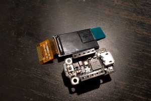
It started when I looked at an integrated LED display in my junk^Wspares box. This came from an old 386/486 era PC and could display the clock frequency up to 99 MHz. As installed it displayed only two speeds, normal and turbo, selected by a push button switch. A quirk was that the digits were yellow but the MHz (which would have been permanently lit) were in red. I liked the dual colours.
I wondered if I could make a clock display out of this. With only two digits I would have to multiplex hours and minutes. It occurred to me that I could display 12:34 as 12 H, followed by 34M.
There was another quirk and that was the MHz part only had 7 "segments". The vertical bars of the M were a segment each. The v in the middle was another segment. Similarly for the vertical bars of the H. However the middle bar was joined with the top of the z, and the final segment was the < of the bottom of the z. This meant that I would always have a "hyphen" after the H, so 12:34 would be displayed as 12 H-, then 34M. I will call this a feature. 😉
Each of the MHz "segments" comprised two red LEDs in series, for a forward voltage of about 3.6 V whereas the yellow segments were single diodes with a 1.9 V forward voltage. Obviously such a display was a custom made part for the PC manufacturer. That's why you will not be able to reproduce this clock, unless you have rescued an identical display. But if you desire you can modify the software (mostly take out the code that handles the hour/min multiplexing) to drive a conventional 4 digit display.
Goals
I made this clock to tackle these challenges:
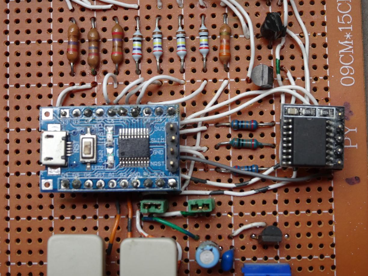
- Program the STM8, in particular the STM8S103F6, in C using SDCC and a ported Standard Peripherals Library
- Multiplex hours and minutes on 2 digits
Wiring
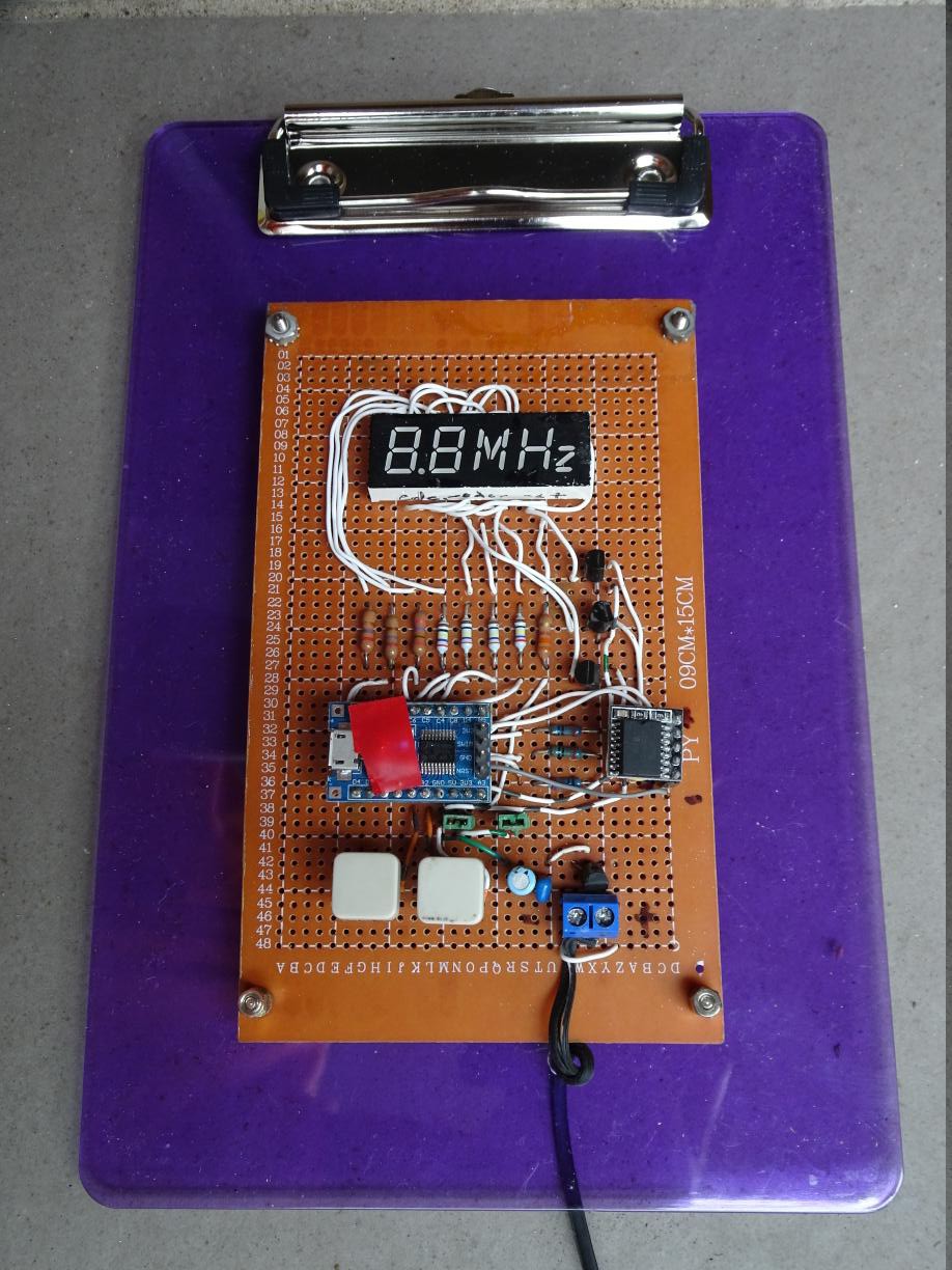
As I have only one display, it would be a waste to get at least 5 fabricated by a PCB house, and there would be a long shipping delay, unless I pay even more for expedited shipping. So I wired up the project on a perfboard. It's ugly, and even worse on the other side so I won't show that.
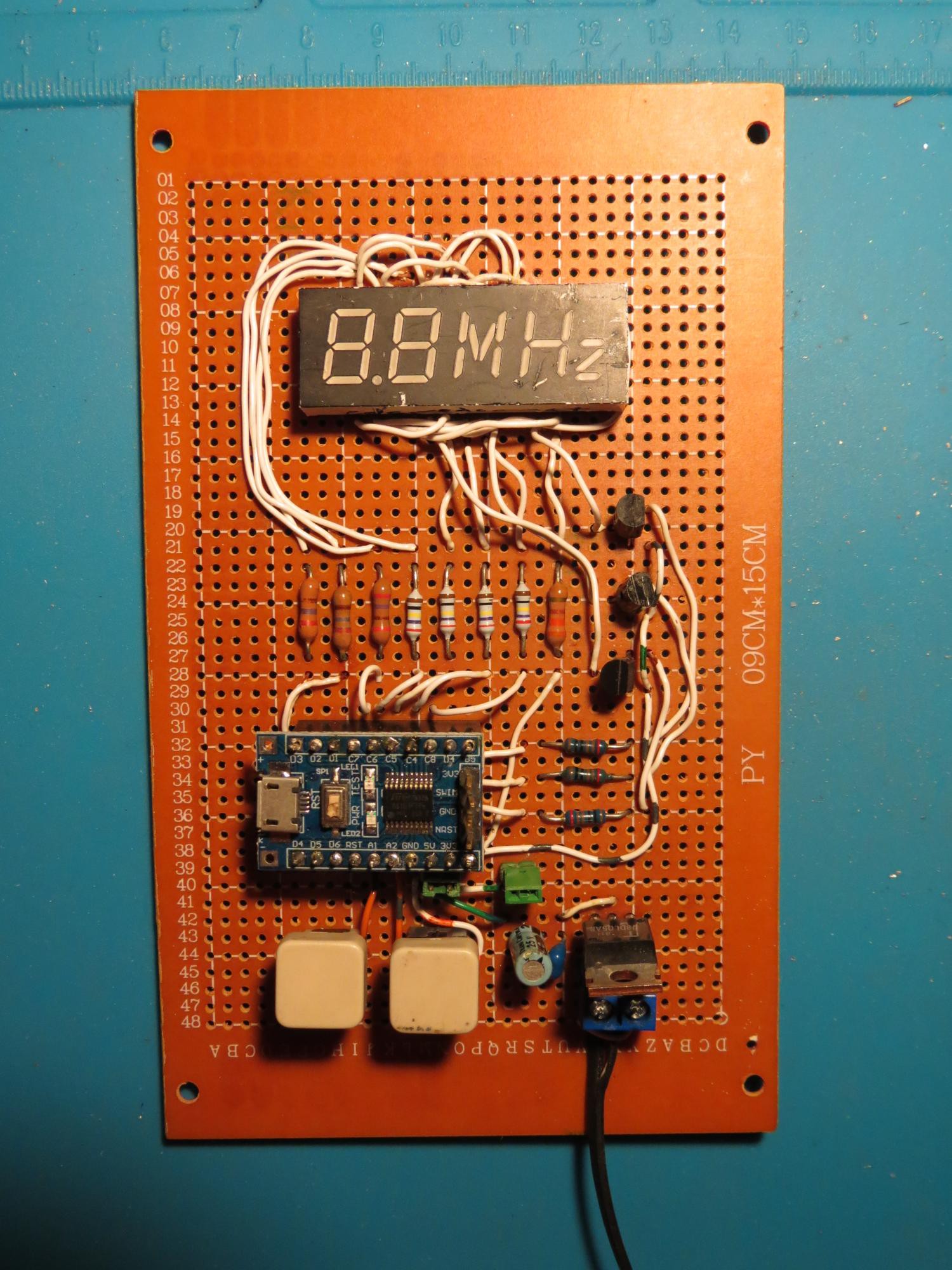
By the way the buttons are also recycled from PCs; they used to be reset buttons. The power supply is a recycled Nokia charger, feeding a 7805 voltage regulator.
There were quite a few joints to solder, that's what happens when you turn a non-multiplexed display into a multiplexed one, so I was glad I was only making one board. Testing showed besides a handful of short circuits and dry joints, a couple of boo-boos: I thought the cathode driver transistors had an EBC footprint but they were ECB. Duh. So a little rerouting of the wires. Another small rerouting was needed because I had transposed two pins of the display, swapping segments b and g of the second digit.
But eventually it passed and I connected it up to an Arduino to display a periodic pattern.
Software
SDCC supports the stm8 architecture. I needed definitions for the STM8 resources such as the registers. I wondered why they did not come with SDCC. To cut short a long adventure down a rabbit hole, it turns out that initially ST did not provide include files and libraries under a suitable license for open source. Eventually they realised their mistake but by then workarounds were swirling around the Internet. However there has been a port of the official Standard Peripherals Library to SDCC. You can read the instructions for building SPL on Linux to get the include files and the library. The advantages of using these includes and library are that: the code becomes more self-documenting, if prolix; there is some error checking of usage; and the SPL for STM32 is similar when you want to reuse the knowledge.
I also used Adam Dunkels' Protothreads for the switch handling.
Firmware for a MCU based clock has several subsystems. I indicate the C source file that handles each subsystem. It may be useful to refer to the source code.
- The timekeeping code (tod.c) which counts subseconds, seconds, minutes and hours
- The periodic timer (tick.c)...


 deʃhipu
 Saimon
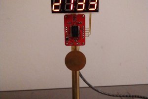
 Pierre-Loup M.
 Bharbour
You've been HaD'ed, Master Ken !
https://hackaday.com/2020/10/25/a-unique-display-makes-an-unusual-clock/