lion mclionhead
-
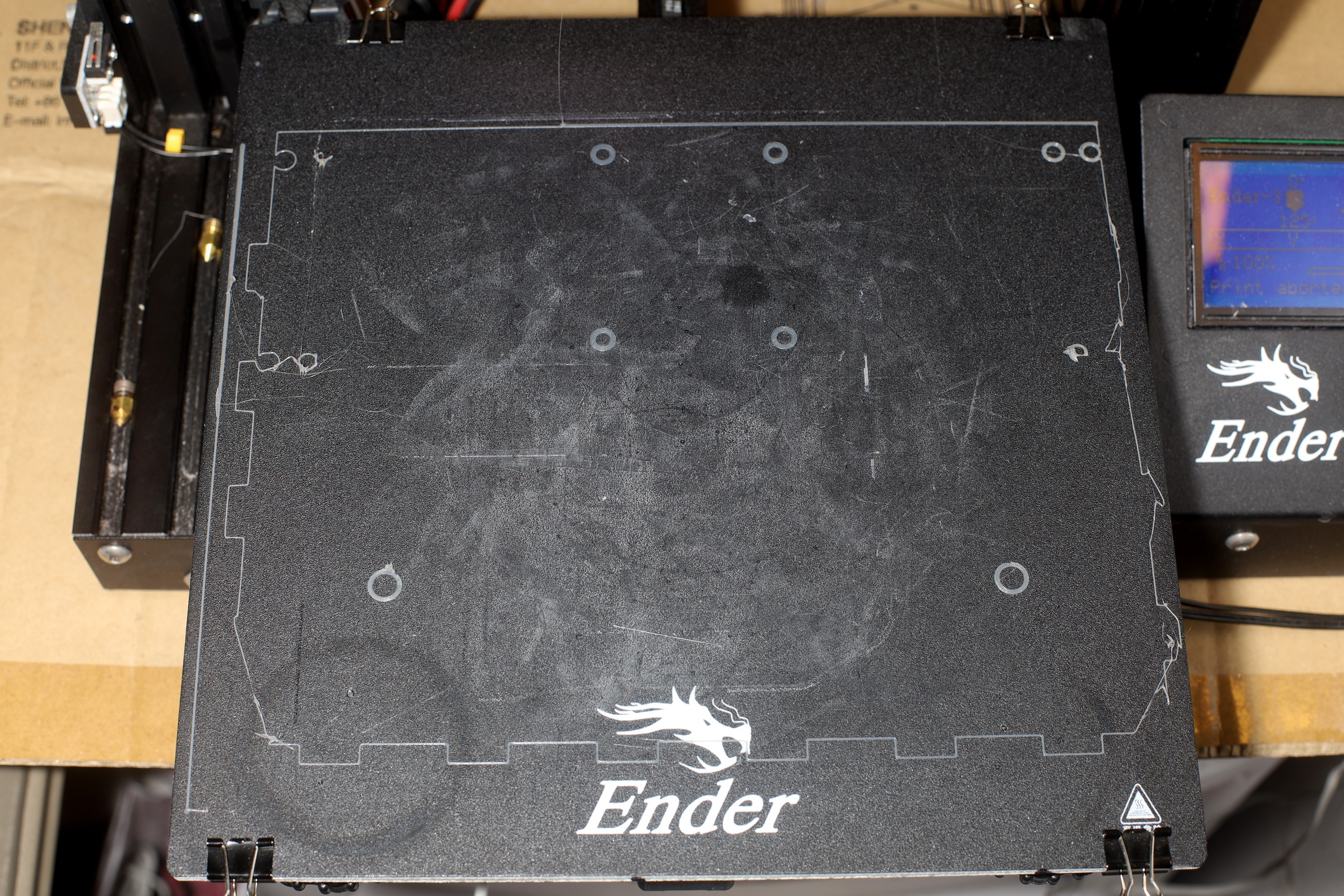
Magnetic bed
04/04/2022 at 21:51 • 0 commentsThe stock buildtak on FR4 bed had problems with air pockets between the buildtak & FR4 & not sticking flat on the aluminum. The solution was seen as the mighty
"Build Plate Ultra Flexible Removable Magnetic Build Surface Hot Bed Cover for Ender 3"
https://www.amazon.com/dp/B084YSZFXL
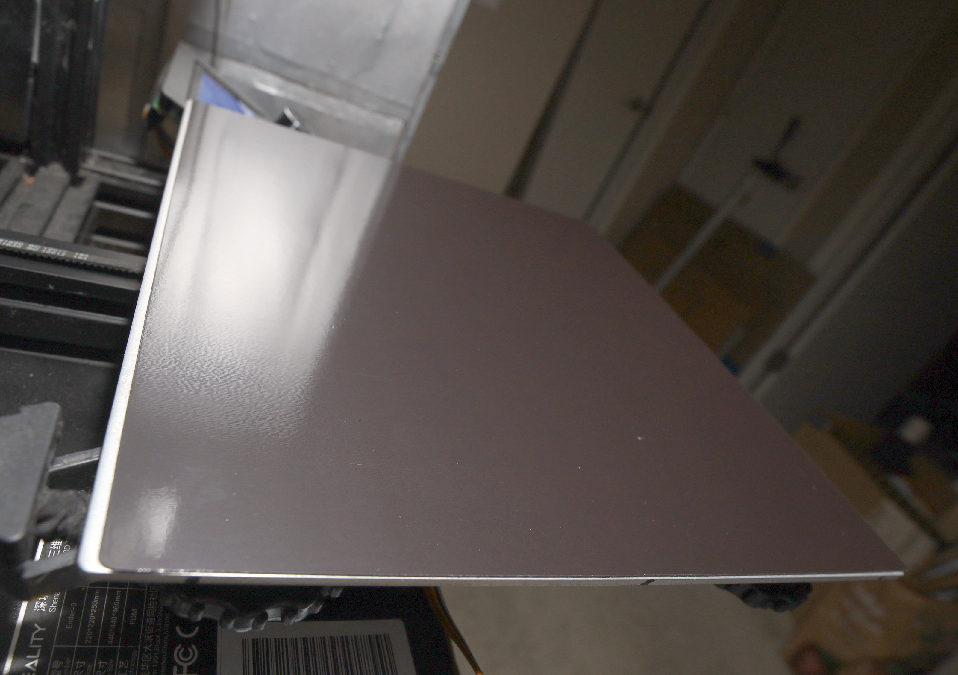
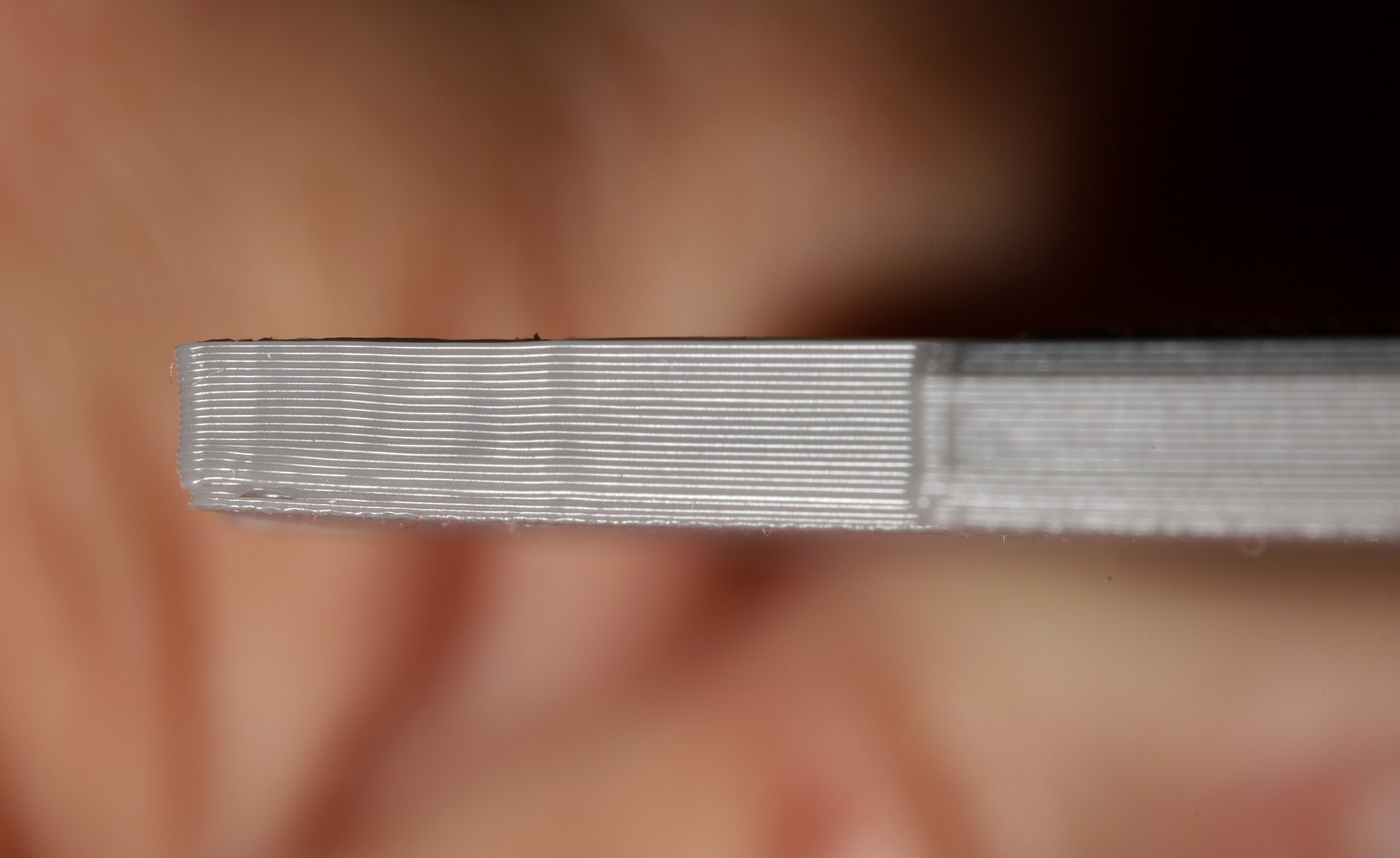
It's overall an improvement. There are no more discernible air pockets. There's much less warping. The mane problem is sticking the adhesive magnet on the aluminum without creating air pockets. The lion tried to stick down the back edge, then roll it forward but was off by 3mm.
![]()
![]()
Taking it off & trying again would probably damage it or trap air bubbles. It still managed to conduct enough heat. The polarity of the magnets in bottom pad has to match the polarity of the magnets in the top pad.
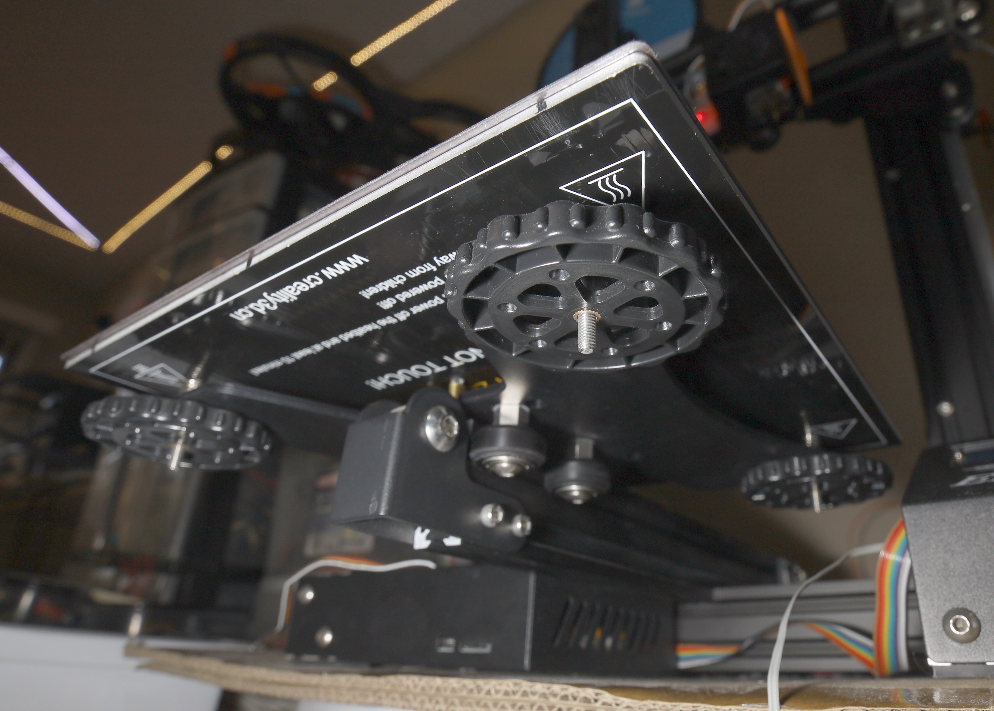
There haven't been any air pockets when sticking down the buildtak magnet. The 2 magnets create a uniform bond to the aluminum with minimal warping.
Having 2 magnet pads between the buildtak & aluminum means less heat gets through. Fortunately, the magnetic buildtak is much stickier than the stock bed. 50C bed temperature was enough for PLA while the stock bed needed 65C. 0C with a 1st layer temperature of 220C is essential for TPU. Higher layers for TPU can be 250C.
![]()
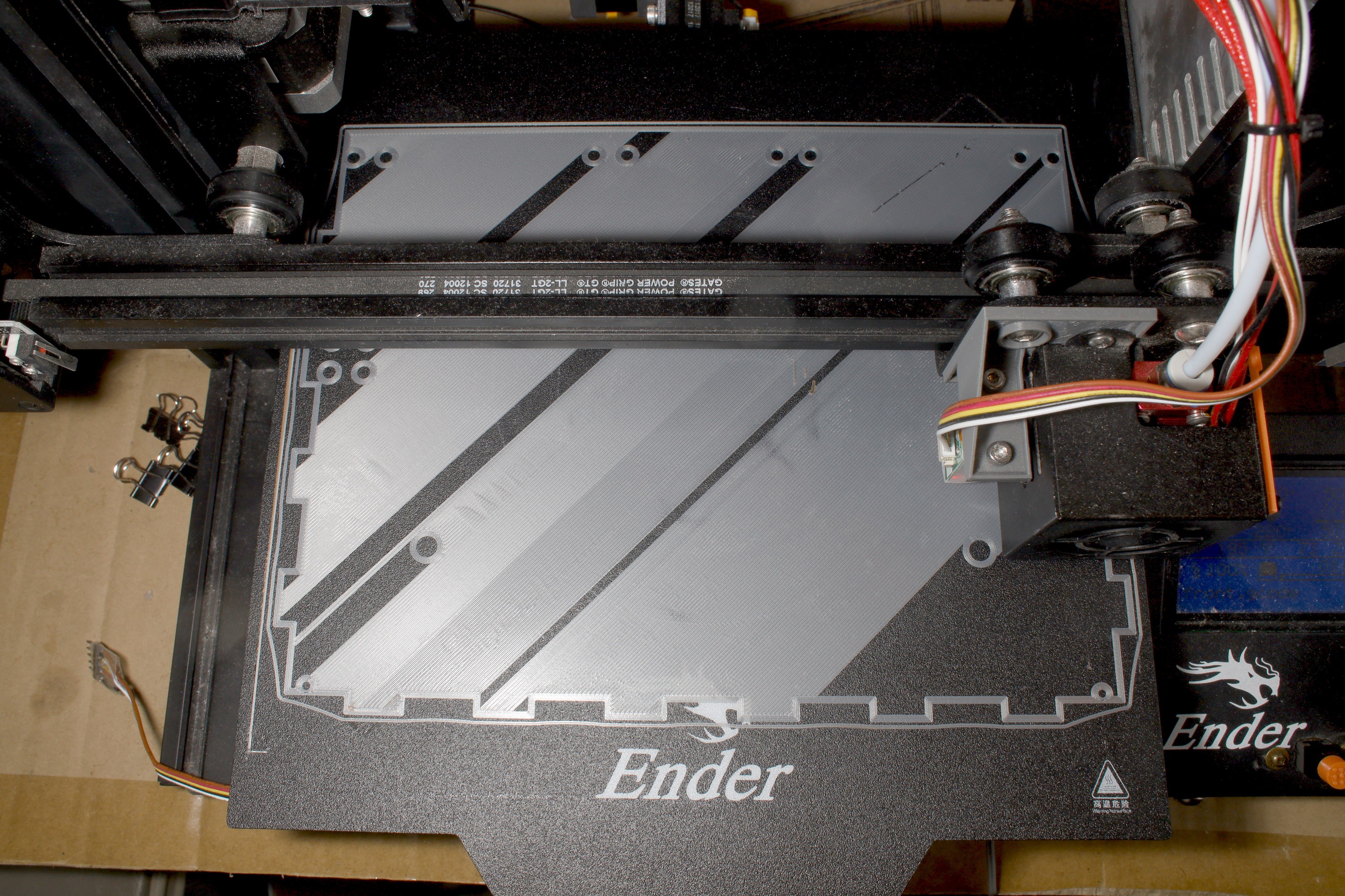
Combined with automatic bed leveling, the magnetic bed yielded gootuber quality 1st layers, all the way from edge to edge. The mane problem was the magnetic bed caused the front row of probe points to always be .1mm lower, almost like a firmware bug more than a bed deformation. It could be because the front row is 1st to be probed & there's a change in bed height in that motion.
No-one really knows why the pogo probes have constant errors like this. They do provide manual tweeking in some firmware. The memory constrained Ender 3 could use some gcode commands, but only if the errors changed. The easiest solution for a constant errors was hard coding the firmware & flashing.
The mane problem with the bed is it's very fragile. Any nozzle crash leaves a hole. Fold it sharply & it leaves a crease. It tries to fold sharply & form creases when removing prints. Waiting for the print to cool, using the spatula & xacto knife is essential for tough prints.
-
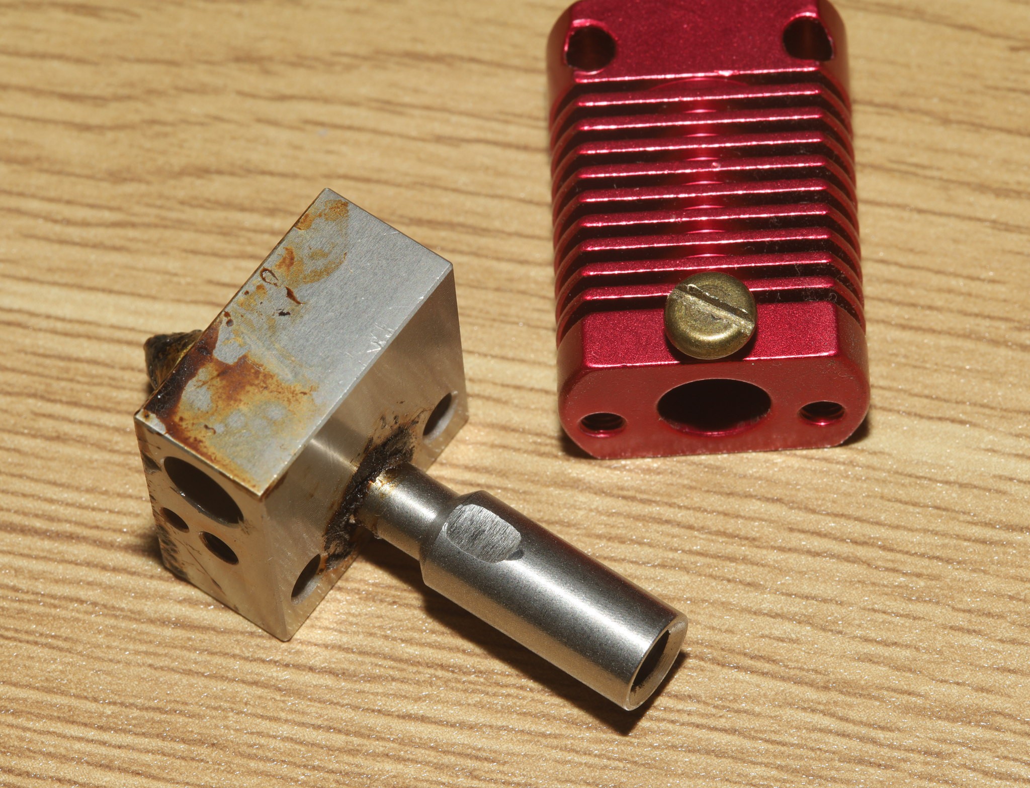
High temperature nozzle
12/11/2021 at 08:43 • 0 commentsAfter stripping a heater, the lion kingdom got a copper heater for higher temperatures.
https://www.amazon.com/dp/B09DS1P9VJ
Instead of what was pictured
![]()
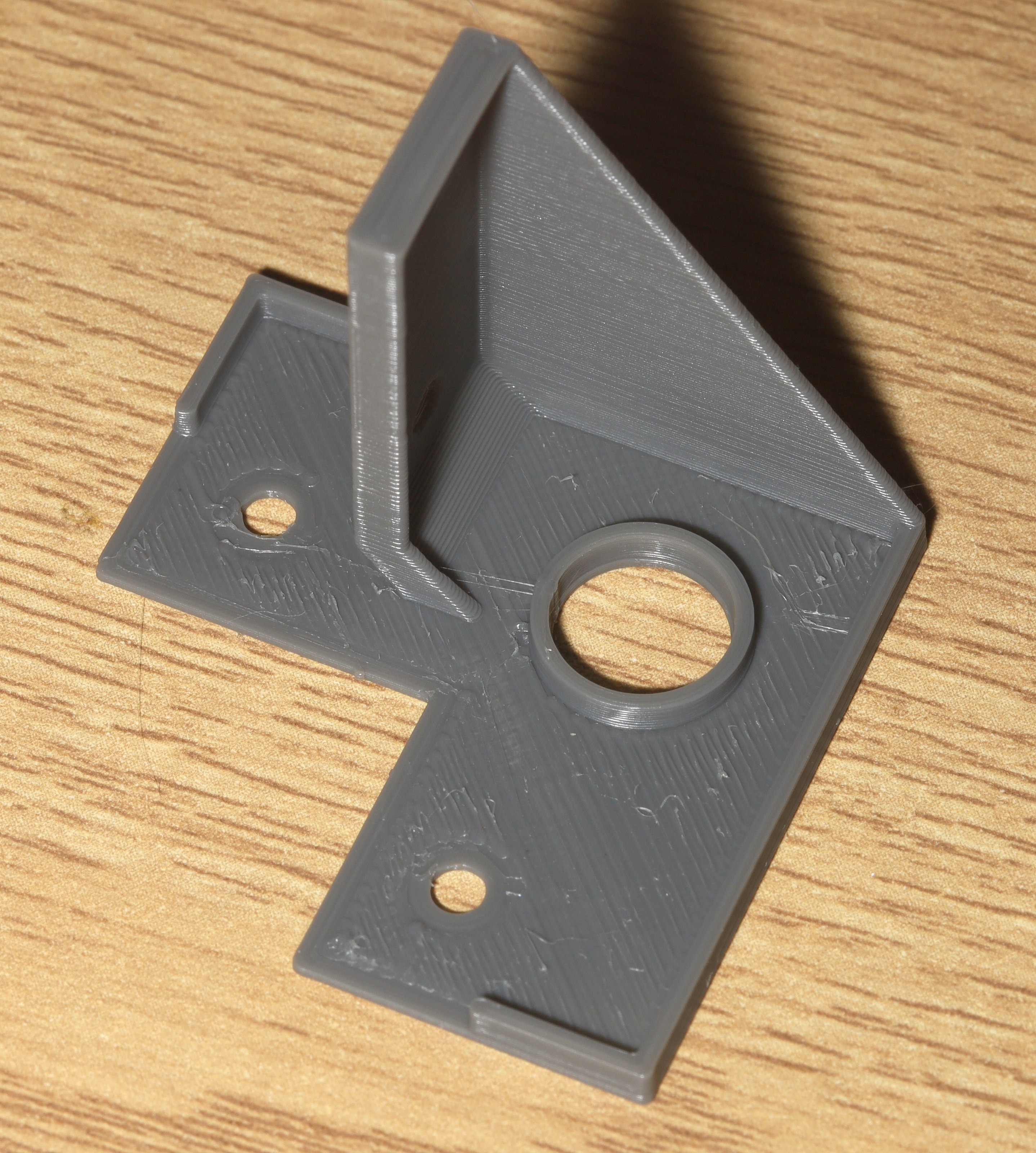
The actual product had no holes for the studs which resist the torque during a nozzle change.
![]()
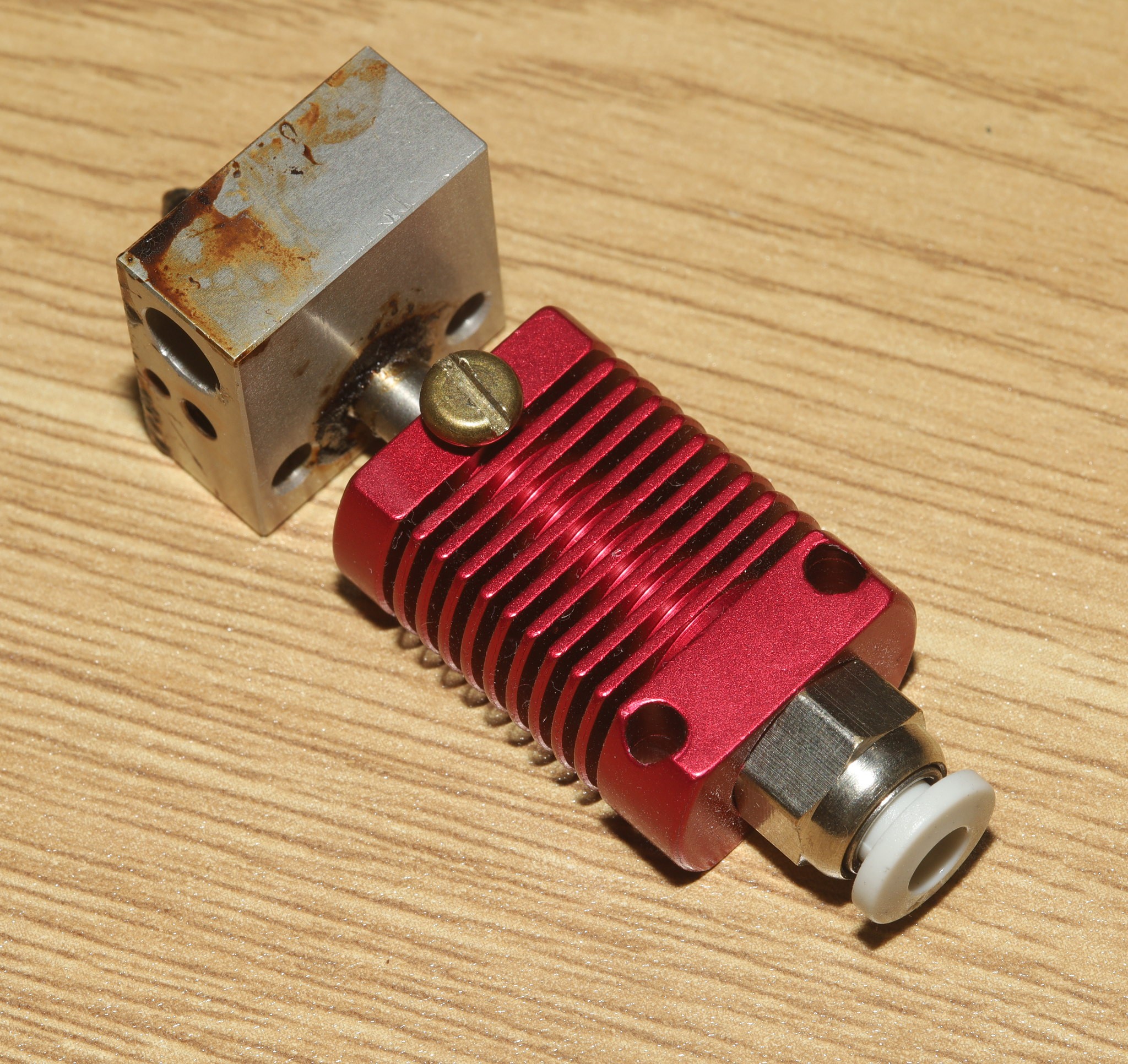
There was an experiment in resisting nozzle changes by grinding a flat & using a bigger set screw.
![]()
But tightening enough to resist nozzle changes stripped the heat sink.
![]()
The lion kingdom resigned itself to a future of grabbing the heater with pliers to resist torque while changing nozzles.
The most expensive consumable for lions has proven to be electricity rather than the filament.
-
Fixing the button
11/24/2021 at 23:05 • 0 commentsMany animals have exited a menu only to find their nozzle temperature was suddenly too cold or their probe Z offset was .1mm too high. For animals who destroyed a print by trying to exit from a menu, the solution is to whack on a separate button instead of using the dial as a button.
![]()
![]()
The hardest part is drilling through the 2mm thick depleted uranium steel armor that is the front panel.
-
Mane filament colors
11/05/2021 at 22:29 • 0 commentsLions never print in any clear filament because
it's what prison gadgets are made of. The mane colors are
silver for the default material
orange for high visibility gadgets & simulating wood with a brown sharpie
black for anything flexible.
A dedicated spool of brown would be good for simulated wood, but might not be as realistic as orange with brown sharpie.
-
1st nozzle burn
11/05/2021 at 05:40 • 0 comments![]()
![]()
Felt the pointy end & ejected before feeling any heat. Fortunately, lions don't need to feel heat to know what's coming.
-
Overclock the Ender 3 display
09/28/2021 at 19:59 • 0 commentsYou can make the display slightly faster. It uses software SPI. For Marlin 1.1.x, the timing values are defined in Conditionals_LCD.h
#elif ENABLED(CR10_STOCKDISPLAY)

  #define REPRAP_DISCOUNT_FULL_GRAPHIC_SMART_CONTROLLER
  #ifndef ST7920_DELAY_1
//    #define ST7920_DELAY_1 DELAY_NS(125)
    #define ST7920_DELAY_1 DELAY_NS(64)
  #endif
  #ifndef ST7920_DELAY_2
//    #define ST7920_DELAY_2 DELAY_NS(125)
    #define ST7920_DELAY_2 DELAY_NS(64)
  #endif
  #ifndef ST7920_DELAY_3
//    #define ST7920_DELAY_3 DELAY_NS(125)
    #define ST7920_DELAY_3 DELAY_NS(64)
  #endif

#elif ENABLED(MKS_12864OLED)
The lion kingdom managed to get them down to 64, but no lower.
More SPI delays are defined in ultralcd_st7920_u8glib_rrd.h
ST7920_WRITE_BYTE, ST7920_WRITE_BYTES, ST7920_SET_CMD, ST7920_SET_DAT, ST7920_CS
all have delays but the lion kingdom didn't have any luck reducing those.
-
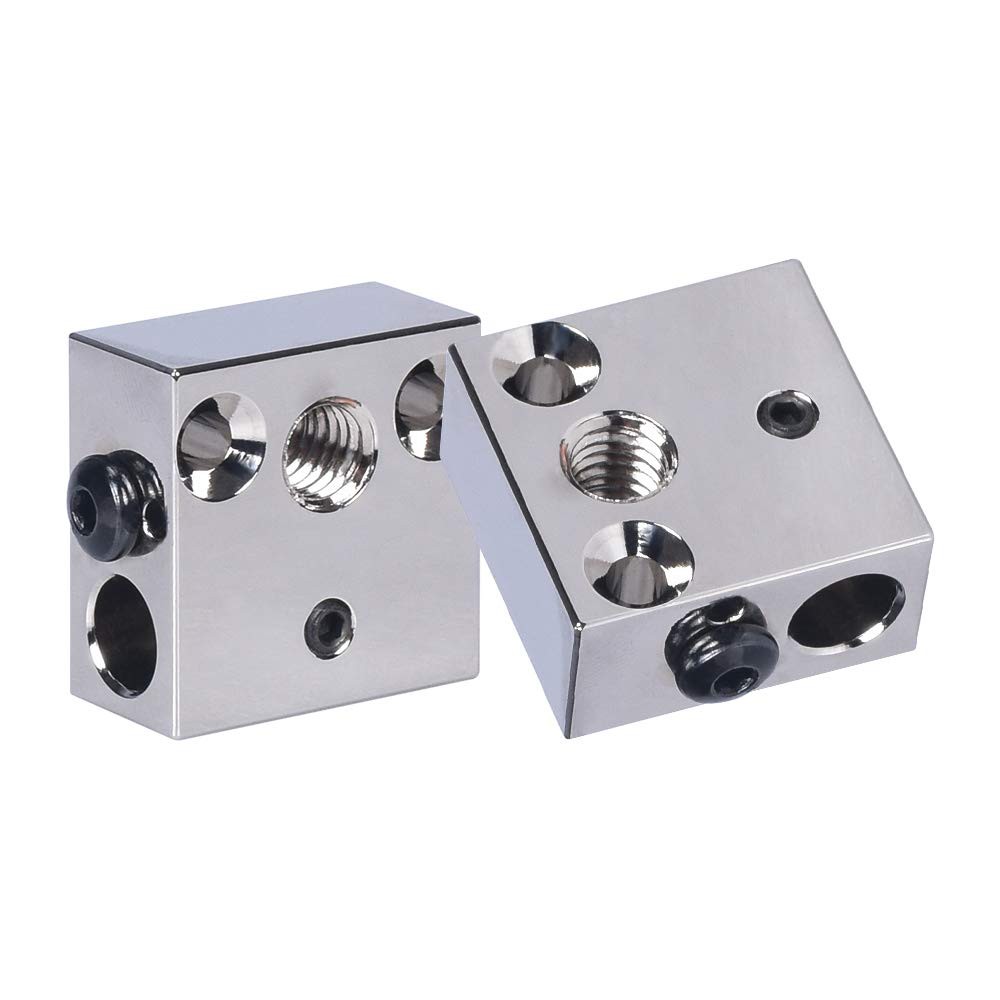
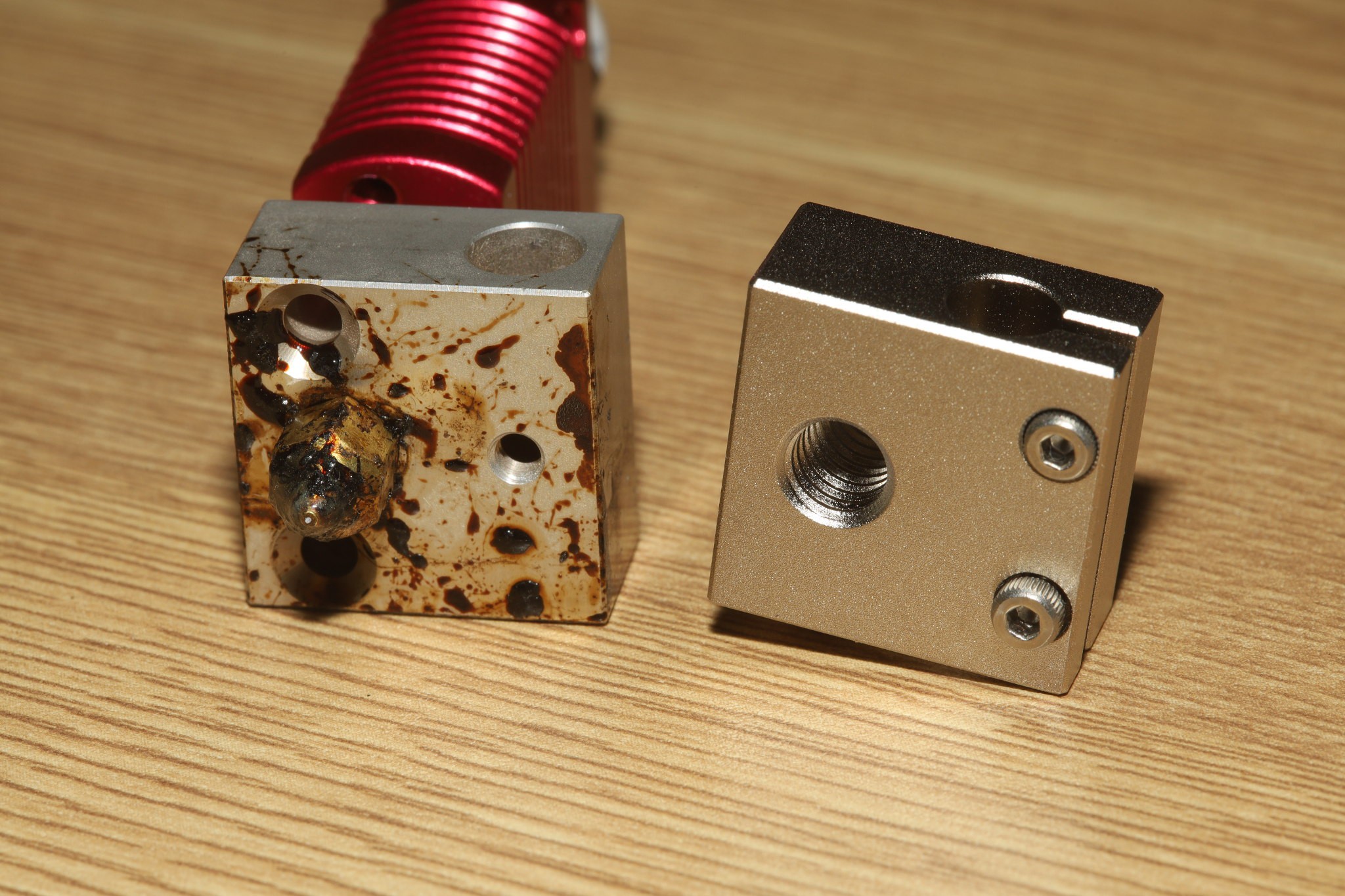
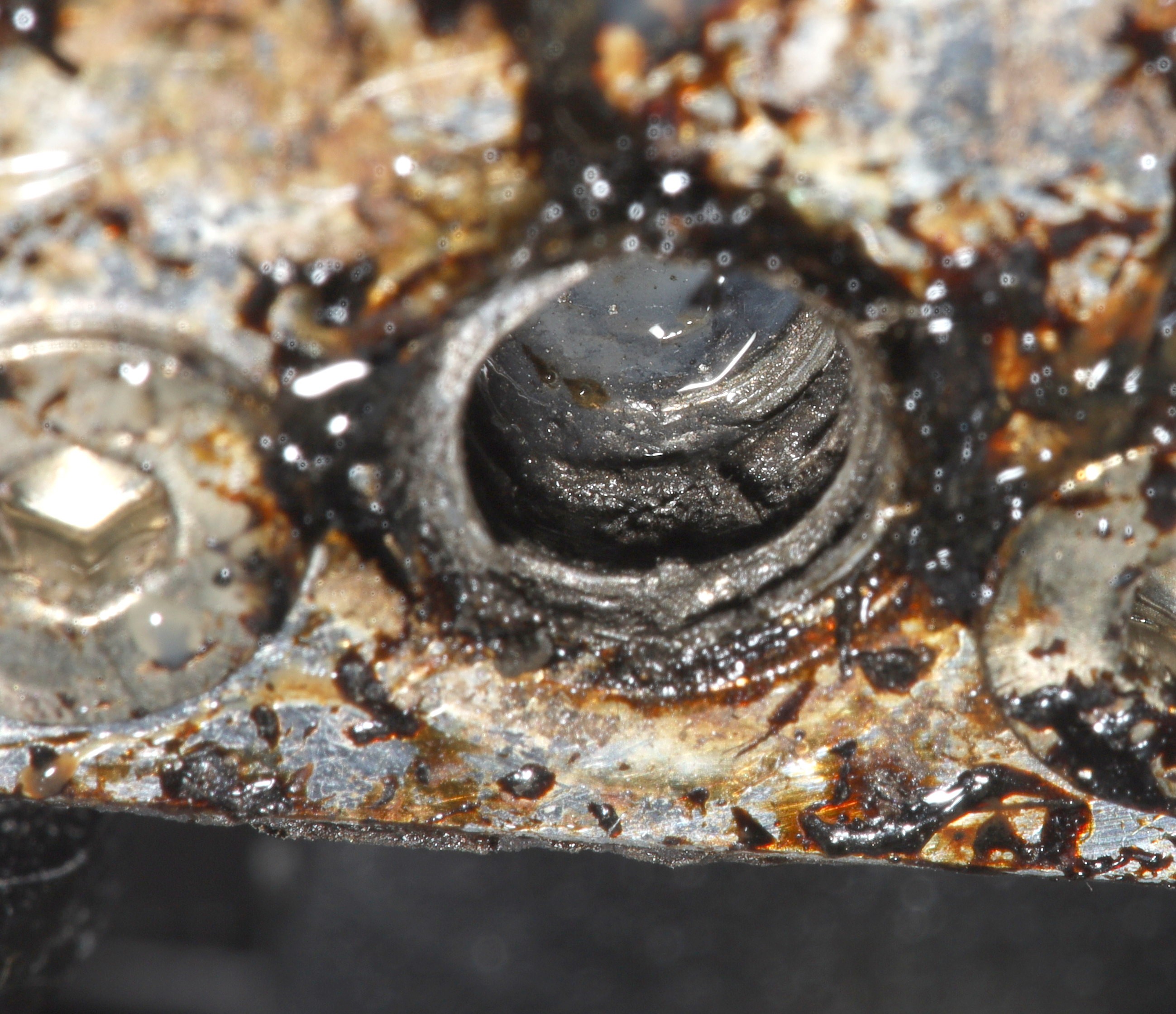
Ender 3 heat block stripping
09/12/2021 at 06:37 • 0 commentsA common problem for animals who frequently change nozzles is the heat block getting stripped.
![]()
![]()
They're all made of aluminum. The stock nozzle had red thread locker. The maximum torque before stripping probably isn't enough to get a reliable attachment. Replacing just the heat block is a huge pain, manely because all the bits which have to be removed can only be removed when they're hot, so the lion kingdom replaced the heat block, heat sink, heater, & thermocouple.
-
Freecad/Blender vs Fusion 360
09/07/2021 at 07:30 • 0 commentsIt feels like the lion kingdom would save a lot of time & effort by using Fusion 360 instead of Freecad with a pile of workarounds in Blender. There's just the memory of Blender becoming the world's standard 3D animation program after lions used Maya for years. Then kicad became the world's standard electronics design program after lions used Eagle for years. Arguably, Altium Designer is now the world's electronics design program but kicad got a lot of publicity a few years ago.
Lions have come to rely on being able to access a lot more than 10 CAD files at any given time. These CAD files stay in the same directories as software & electronical files. They're all managed by the same git repositories with revision histories.
It would be another hoop to have the CAD files exclusively online in an autodesk server while all the other bits are still on the gits. Then, these CAD files would have to be constantly toggled read-only to get beyond 10. The lion kingdom uses Comca$t internet which constantly goes down for days at a time but is never quite worth the hassle of switching out of.
Fusion 360 still has a lot of problems compared to Freecad booleans.
-
Fixing FreeCAD models in Blender
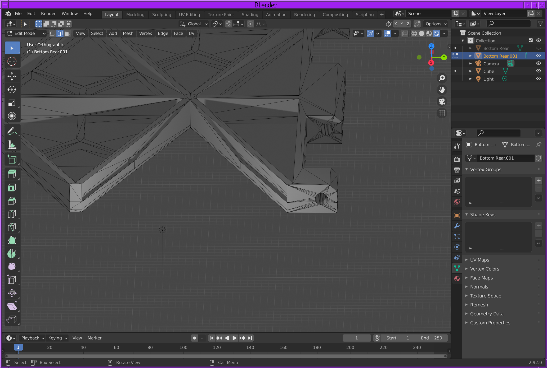
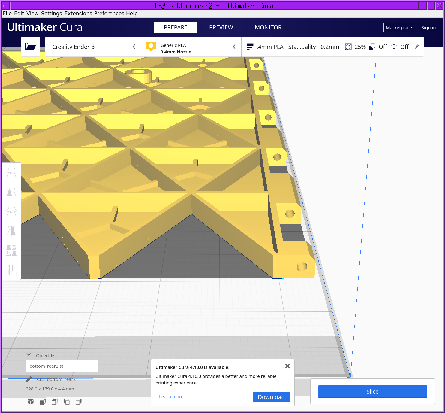
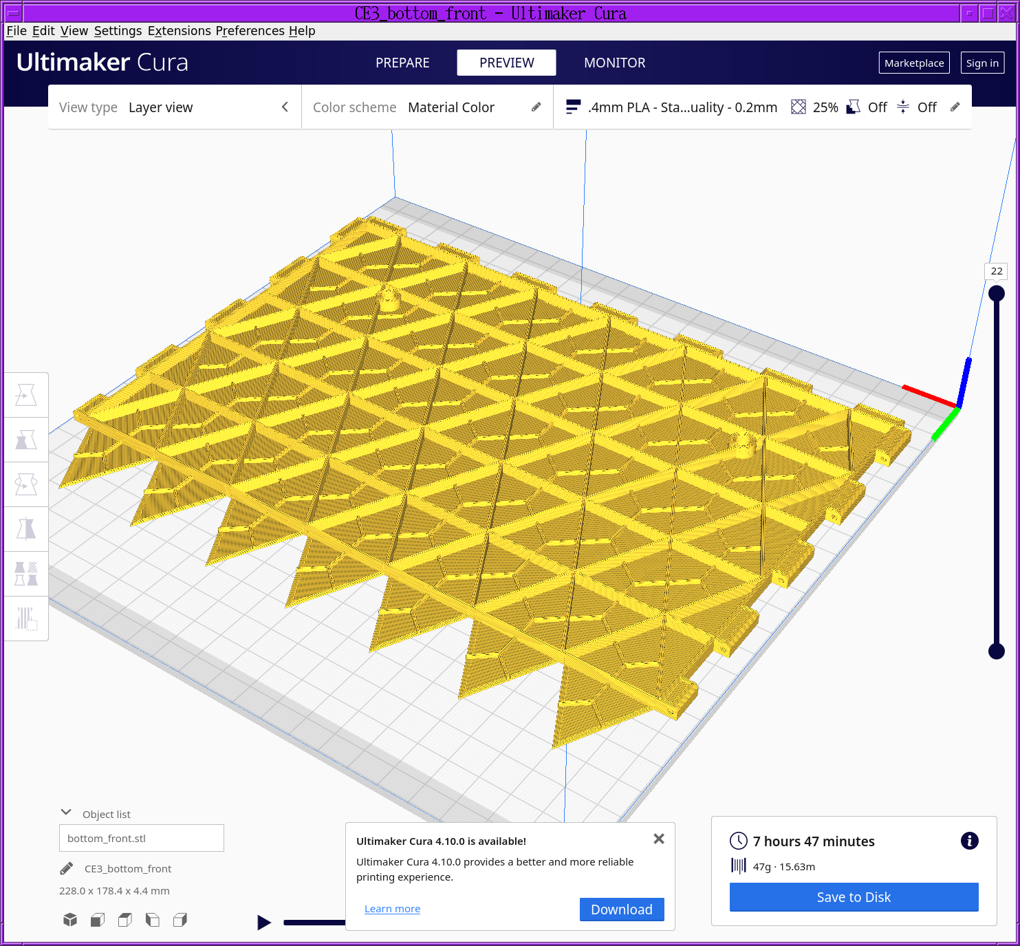
09/06/2021 at 07:50 • 0 commentsFreecad has a famously bad boolean solver, but creating temporary booleans is essential to split models up for printing. When it fails, it normally leaves off a face. Cura can't slice it unless it's a closed solid.
![]()
Cura shows a goofy pattern where a boolean error has happened & it slices it into garbage. Fortunately, you have a friend in the boolean business: Blender. Just go to file->import to import the STL file.
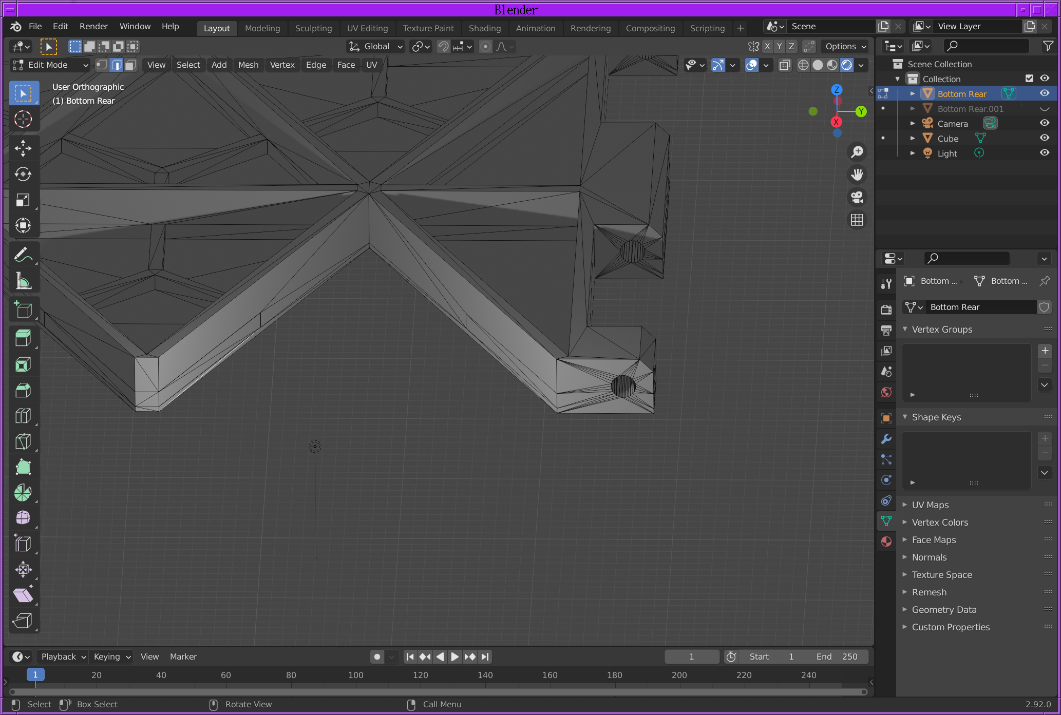
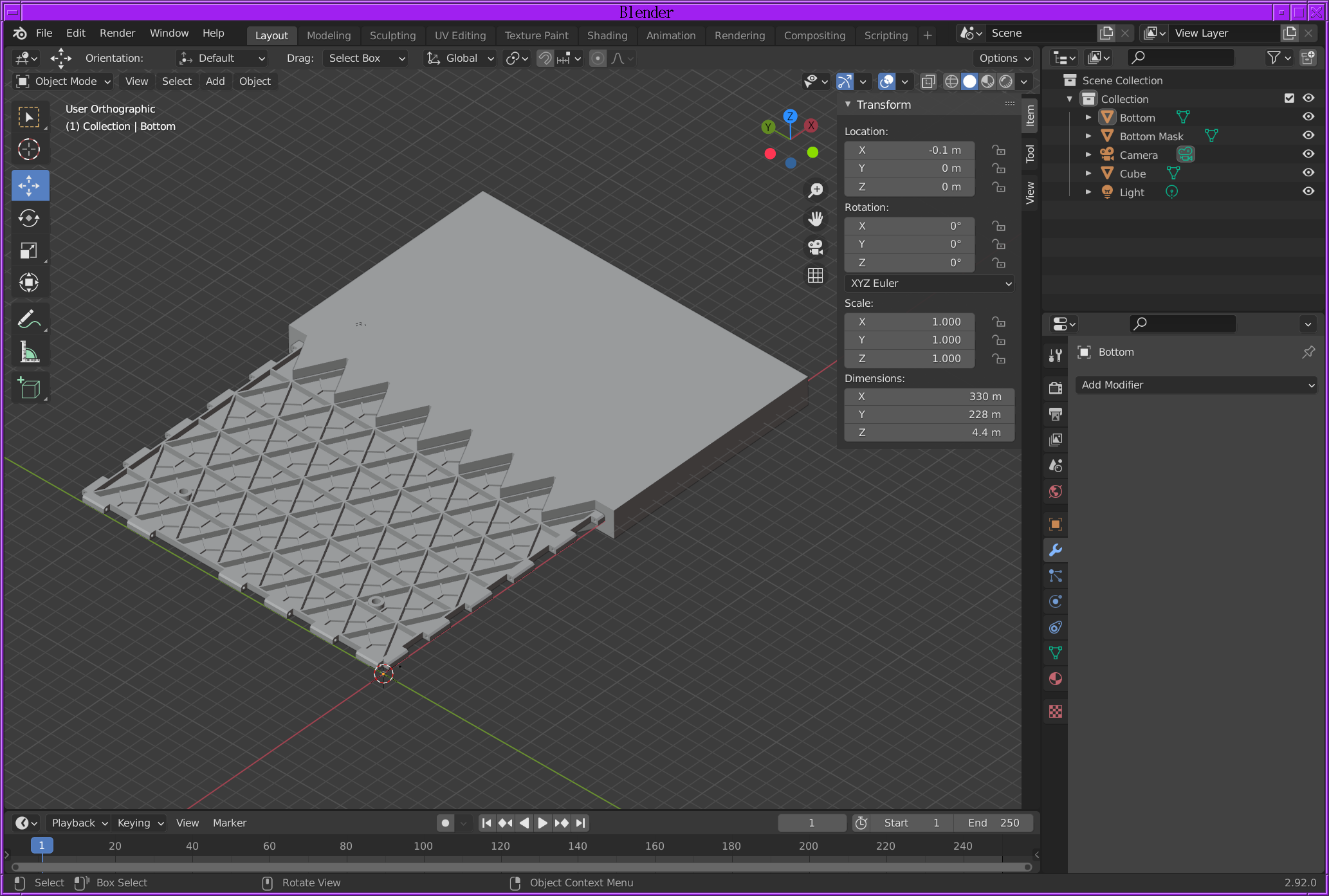
![]()
Blender shows 2 faces are missing. It's just a matter of going into edit mode, hitting C to select the vertices around the holes & hitting F to create faces.![]()
Then, export it as an STL file. Cura is happy to load the STL file generated from blender, with all the right dimensions.
![]()
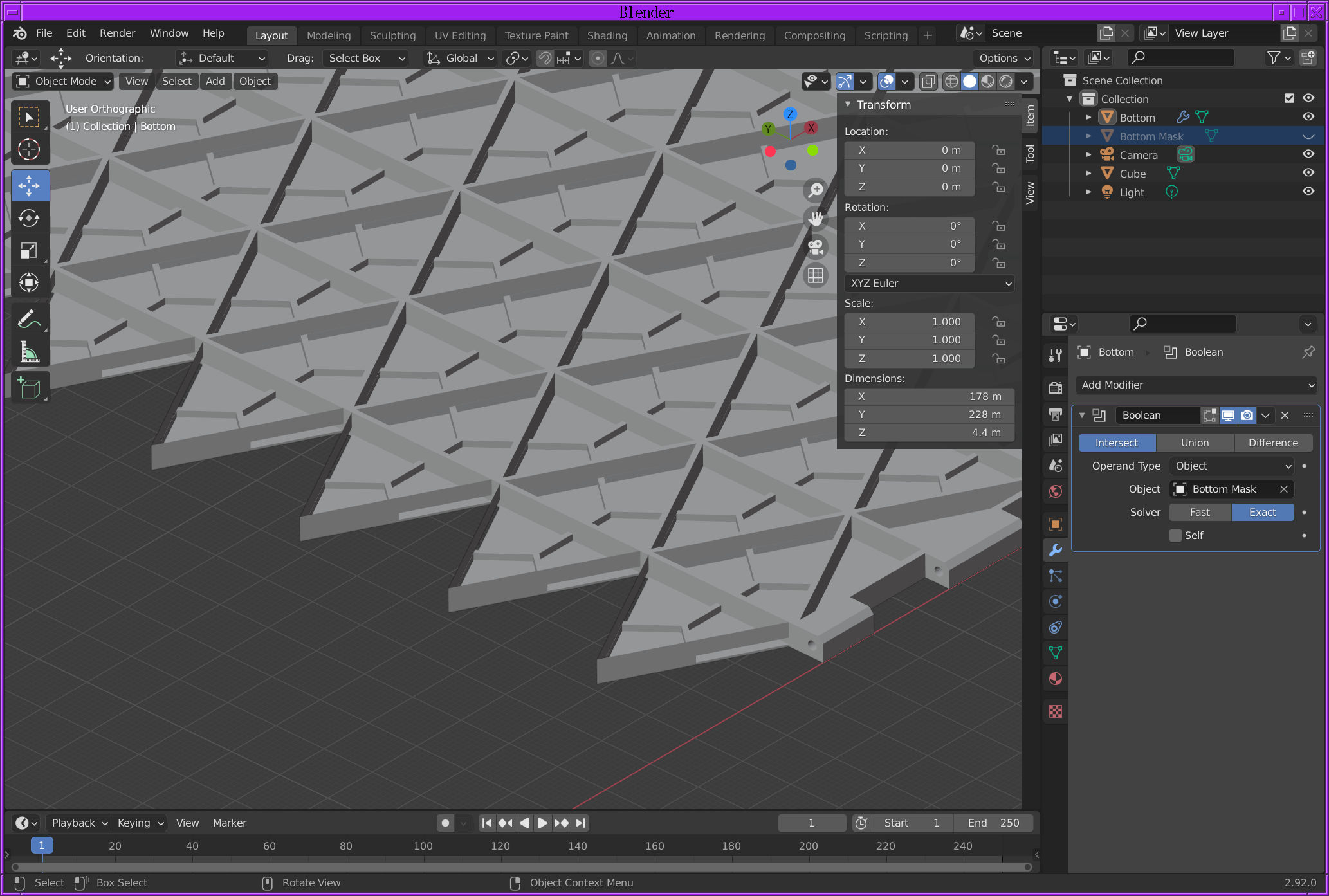
Booleans in Freecad are a pain in the mane anyways, with goofy offsets & goofy tweeks normally required. Blender can import the STL files for the model & print mask.
![]()
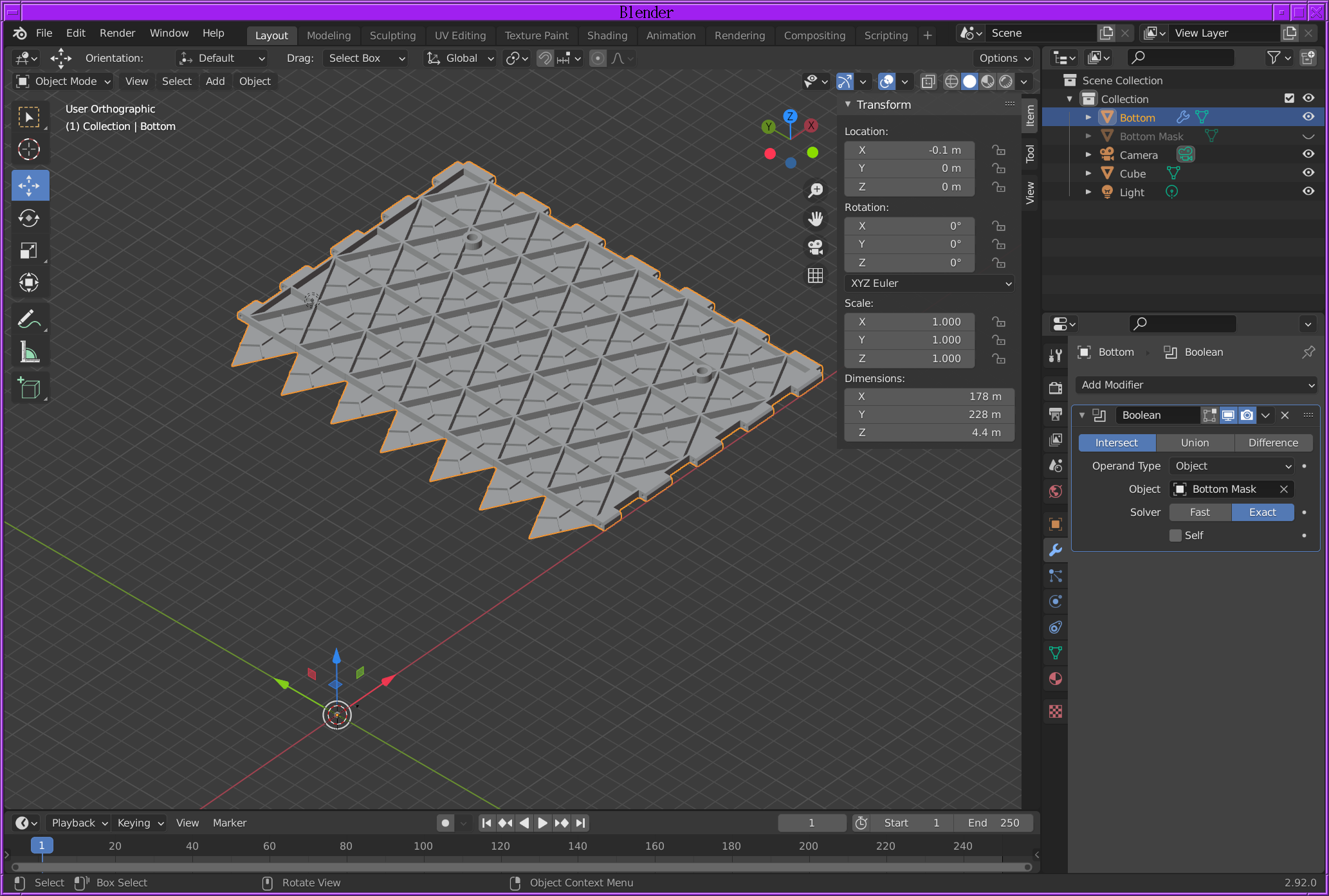
Then apply the boolean by "adding a modifier" to the object to be printed & hiding the print mask object. Of course, we still need a tiny offset to get rid of some dangling faces. At least blender shows the dangling faces instead of completely failing.
![]()
Blender converts 1mm to 1 meter. .1 meter in Blender is .1mm.
![]()
You now have to export the STL file with "apply modifiers" enabled.
![]()
Cura slices booleans from Blender just as well as Freecad.
-
Auto bed leveling with the 3dtouch
09/02/2021 at 21:29 • 0 commentsAutomatic bed leveling has become a standard feature in the last 2 years & has standardized on hall effect sensor pin testers. Hall effect sensors can measure distance down to the .1mm precision required.
The lion kingdom got a cheaper 3dtouch instead of the standard bltouch.
https://www.amazon.com/BZ-3D-Leveling-Printers-Precision/dp/B07ZCZP15F
Tearing it down is a destructive operation, so the only teardown of a sensor is:
There's a solenoid which raises & lowers the pin in order to change the XY position. Then, the hall effect sensor detects when the Z position hits a fixed height & emulates the Z stop switch. There's no analog height output. The user sets a difference between nozzle & probe height.
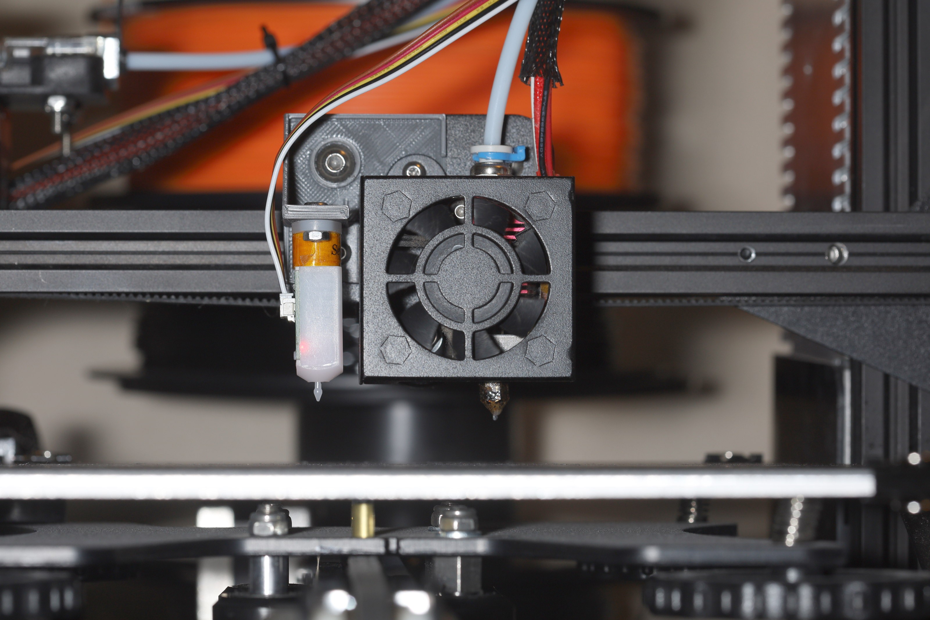
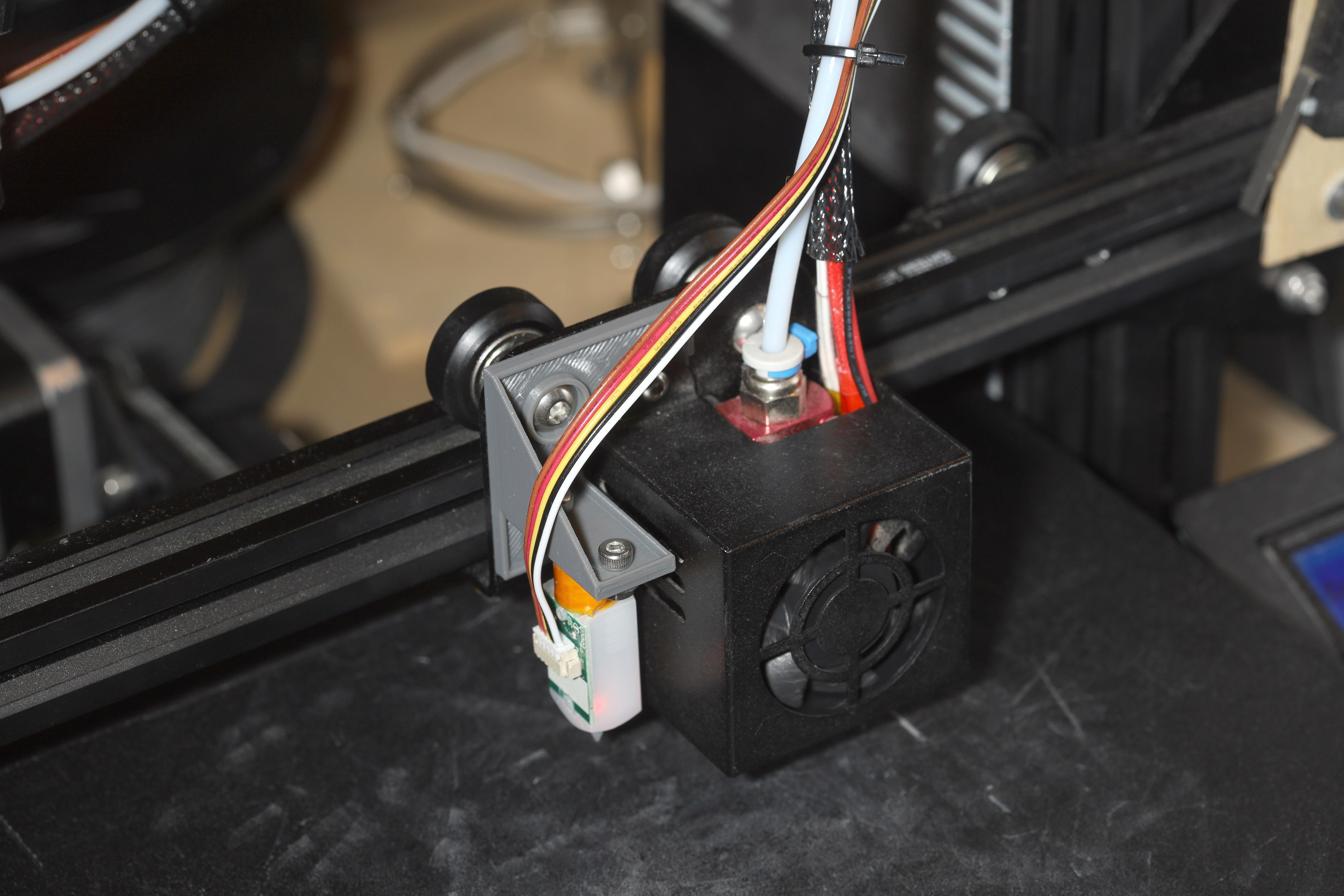
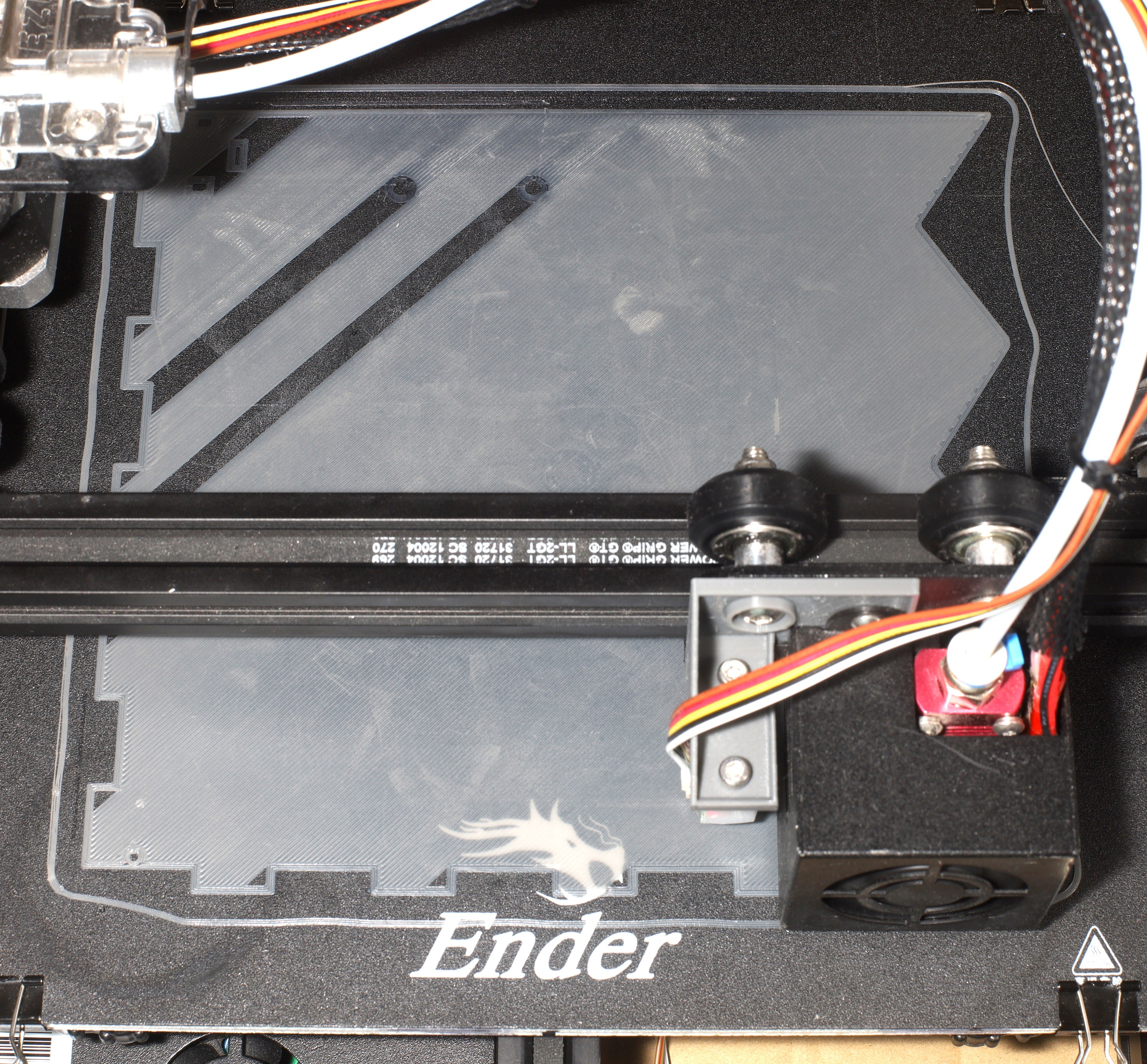
The mane problems are mounting the probe, recompiling the firmware & reconfiguring the gcode. The lion kingdom made a custom mount since all the online ones were junk.
https://github.com/heroineworshiper/utils/blob/master/3dtouch.FCStd
![]()
While this happened, the lion kingdom also ripped off the cooling fan.
![]()
![]()
The only useful starting point came from:
https://all3dp.com/2/ender-3-with-marlin-how-to-install-marlin-firmware-on-your-ender-3/
The firmware has to be Marlin 1.1.x for the Ender 3, not marlin 2.0.x.
https://github.com/MarlinFirmware/Marlin/tree/1.1.x
The board has to be set to Sanguino & the processor has to be ATMEGA1284.
The best firmware notes were in:
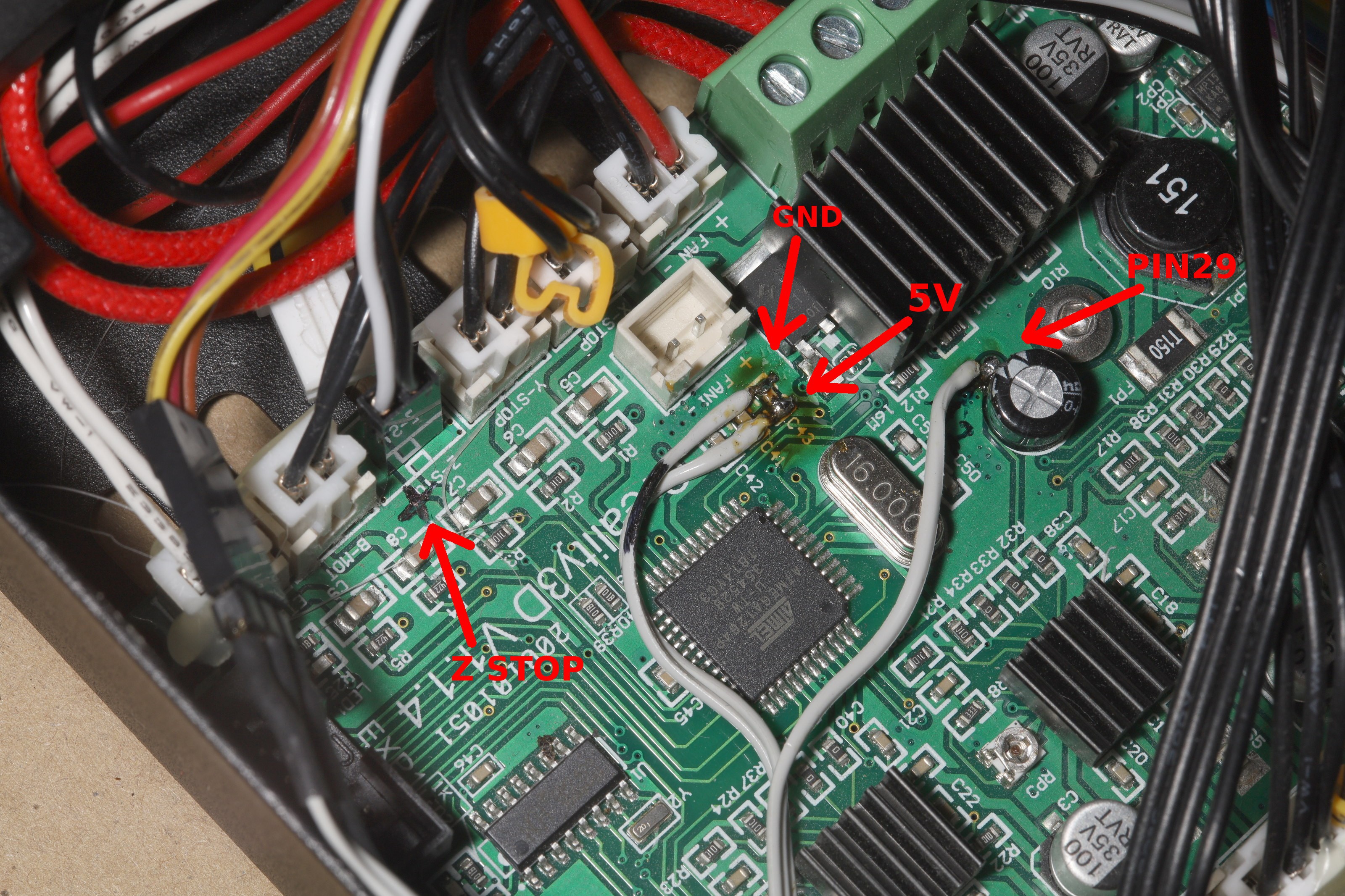
The lion kindom used "PIN29" instead of "PIN27" for servo0 & kept the speaker alive, because you need the speaker to save the settings.
PIN 29 is actually pin 35 on the ATMega 1284, but the internet calls it PIN 29. We find PIN 29 being translated to PORTA2 in
~/.arduino15/packages/Sanguino/hardware/avr/1.0.3/variants/sanguino/pins_arduino.h
Then PORTA2 is pin35 on the 1284. The arduino libraries use some archaic pin numbering which has nothing to do with the datasheet. Pin29 emerges next to a capacitor.
![]()
Programming the Ender 3 bootloader required writing the ArduinoISP sketch on an uno, then setting "Arduino as ISP" as the programmer to write the bootloader on the sanguino. Then, the Marlin firmware could be written to /dev/ttyUSB*. Sadly, the arduino bootloader on this board is crap. 1 problem is Marlin & the bootloader compete for the serial port.
The decision was made to scrap the bootloader & always use ICSP. It didn't free up a meaningful amount of memory, it was real slow, but it worked.
The trick with ICSP mode is you have to take the SD card out. The SD card shares the SPI pins with the programming pins & runs on 3.3V, so it'll get destroyed if you try programming with a 5V arduino.
You need to set the BAUDRATE & SPI_CLOCK in ArduinoISP.ino to 115200 & 200000 to speed up ICSP programming, then write the new ArduinoISP to an Arduino.
The avrdude command required to flash Marlin is given in an attempt to upload the sketch. All the Show verbose output check boxes must be enabled in preferences.
/root/arduino-1.8.15/hardware/tools/avr/bin/avrdude -C/root/arduino-1.8.15/hardware/tools/avr/etc/avrdude.conf -v -patmega1284p -cstk500v1 -P/dev/ttyACM0 -b115200 -Uflash:w:/tmp/arduino_build_951059/Marlin.ino.hex:i
In this case, the baud rate was increased to use the hacked ARduinoISP.
Notes about configuring gcode to level the bed are in
The mane point is it doesn't level the bed unless the gcode contains G29 after the bed is preheated & it gives a G28.
G29 makes it probe & applies the mesh, but requires a preceeding G28 to home the nozzle or it'll crash.
The lion kingdom updated its fixcura.py script to add bed leveling gcode.
https://github.com/heroineworshiper/utils/blob/master/fixcura.py
![]()
The default auto bed leveling firmware failed to access the very edges of the bed. It did incrementally improve the quality of smaller parts.
After giving up on accessing the very edges of the bed, the lion kingdom printed a part which previously worked without auto bed leveling. It was easier to print & slightly more even, but the 2nd layer was under extruded.
The lion kingdom had to set Z_PROBE_LOW_POINT to -5 for it to actually perform bed leveling. The Z axis movement is invisible to the naked eye. Reach in & feel the Z corkscrew to know if it's doing anything.
Probing closer to the edges or in places which best represent the height of the area might help. It can't probe the very right side because the nozzle runs out of room. Even the crazy auzzie bloke showed it not reaching the very right side. The lion kingdom set X_BED_SIZE to 250 to get closer to the right edge.
The mane problem was eventually narrowed down the Z axis not compensating enough. The probing seemed consistent but the nozzle didn't go down enough where it was low & it didn't go up enough where it was high. A simple hack doubling the probing matrix actually improved it enough to print the full width of the bed. It's as if they deliberately divided the probing matrix to make it more conservative.
Marlin_main.cpp: 5586 before print_bilinear_leveling_grid is where you can tweek the matrix.
      #if ENABLED(AUTO_BED_LEVELING_BILINEAR)

        if (!dryrun) extrapolate_unprobed_bed_level();

// HACK
        for(int i = 0; i < GRID_MAX_POINTS_Y; i++)
        {
            for(int j = 0; j < GRID_MAX_POINTS_X; j++)
            {
                z_values[i][j] *= 2;
            }
        }

        print_bilinear_leveling_grid();

        refresh_bed_level();
Using a magnetic bed, the nozzle was always printing closer in the front than the rear. No amount of Z offset, wheel dialing, or rotation of the bed made any difference. The 3D touch was always detecting a higher bed in back than in front. Newer versions of marlin support tweeking the probe points in the GUI, but the best option for the Ender 3 was to hack the Marlin_main.cpp function.
// HACK
        for(int i = 0; i < GRID_MAX_POINTS_Y; i++)
        {
            for(int j = 0; j < GRID_MAX_POINTS_X; j++)
            {
                z_values[i][j] *= 2;
            }
        }

// move right rear away from nozzle
//        z_values[GRID_MAX_POINTS_Y - 1][GRID_MAX_POINTS_X - 1] += 0.1;
// move left front away from nozzle
        z_values[0][0] += 0.1;
// move mid front away from nozzle
        z_values[0][1] += 0.1;
// move right front away from nozzle
        z_values[0][2] += 0.1;
This shows the relationship between the array subscripts & the positions of a 3x3 probing grid. Ideally, there would be gcode commands to tweek the probe points. Months of tweeking the Z offset gave a good enough idea of the required offsets to hard code it.
Another item which might help is shifting the paperclips closer to the center, so the edges aren't as eccentric.
Another problem afflicting bed leveling is the bed compressing from the pressure of filament extruding on it. The Ender 3 bed has an artifact where the adhesive bonding the buildak surface to the fiberglass expands & compresses. The lion kingdom desperately needs a more stable bed.
![]()
The bed in this layer was higher when it printed the outlines. Then, it got squished lower when it printed the crosshatching.
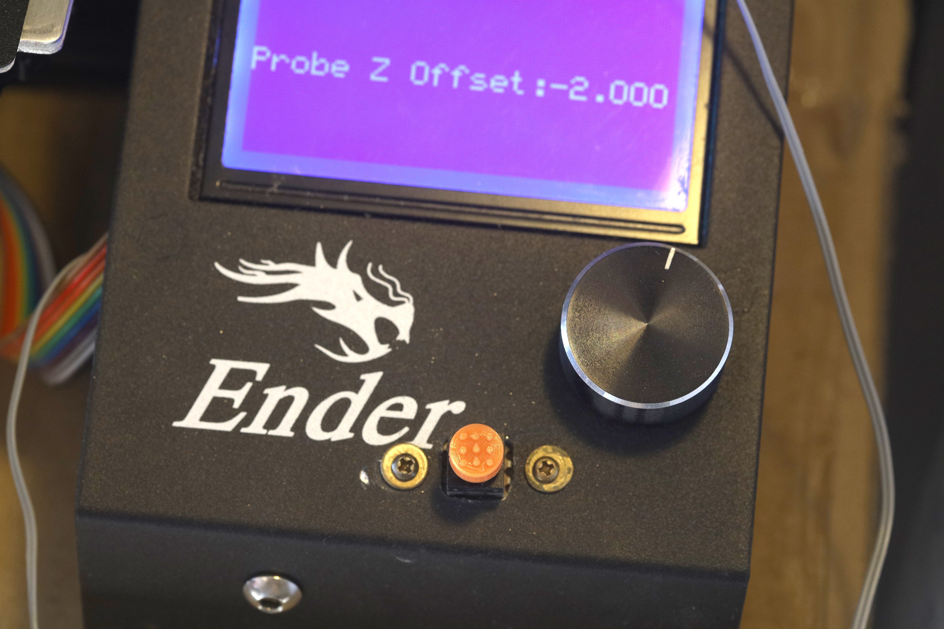
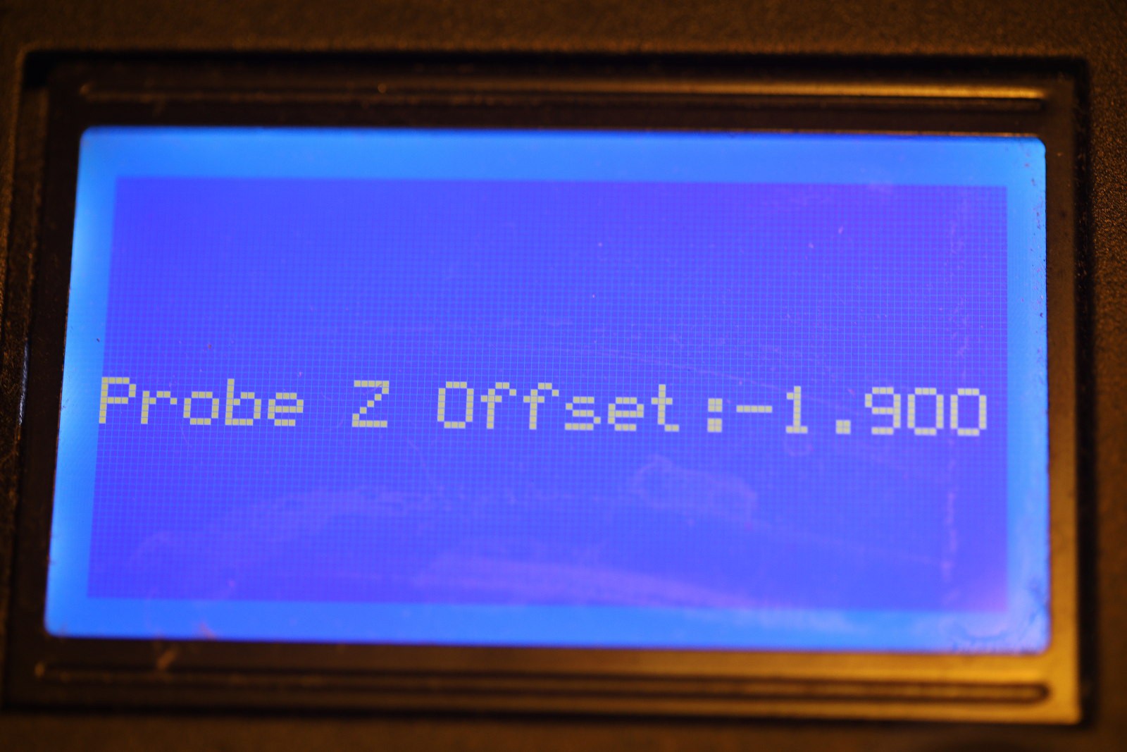
Your biggest ally in automatic bed leveling has proven to be prepare -> bed leveling -> PROBE Z OFFSET
![]()
That's the difference between the probe & nozzle height. It has to be tweeked every time you change nozzles, then saved. Between prints, it seems to vary by .1mm. It can be tweeked while it's printing under tune -> probe Z offset but it can't be saved.
Printing a skirt & tweeking the Z offset is still essential, whenever possible. If there isn't enough room for a skirt, you can try modeling test areas & making sure the slicer prints the test areas 1st.
One thing which doesn't work is adjusting the knobs while printing. That always screws it up when auto bed leveling is active, where before auto bed leveling, it could work around errors.
The Ender 3 USB port
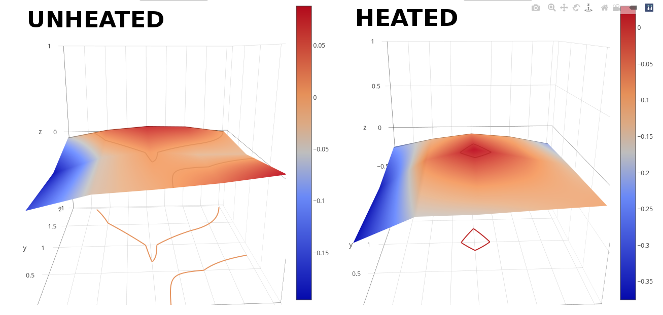
During this process, the lion kingdom discovered the Ender 3 USB port is a serial port with debugging output. It takes G code as input. G28; G29; levels the bed & prints the matrix.
      0      1      2      3      4
 0 -0.155 -0.040 -0.010 +0.030 +0.088
 1 -0.195 -0.043 +0.005 -0.030 -0.030
 2 -0.052 +0.035 +0.075 +0.067 +0.000
The matrix for a 5x3 probing grid has front left as 0,0 & back right as 4,2
Compare to the heated bed.
0 1 2 3 4 0 -0.375 -0.167 -0.160 -0.132 -0.107 1 -0.360 -0.070 +0.030 -0.057 -0.152 2 -0.223 -0.132 -0.073 -0.115 -0.210![]()
You could make a joystick control the print head with an HID to serial program.
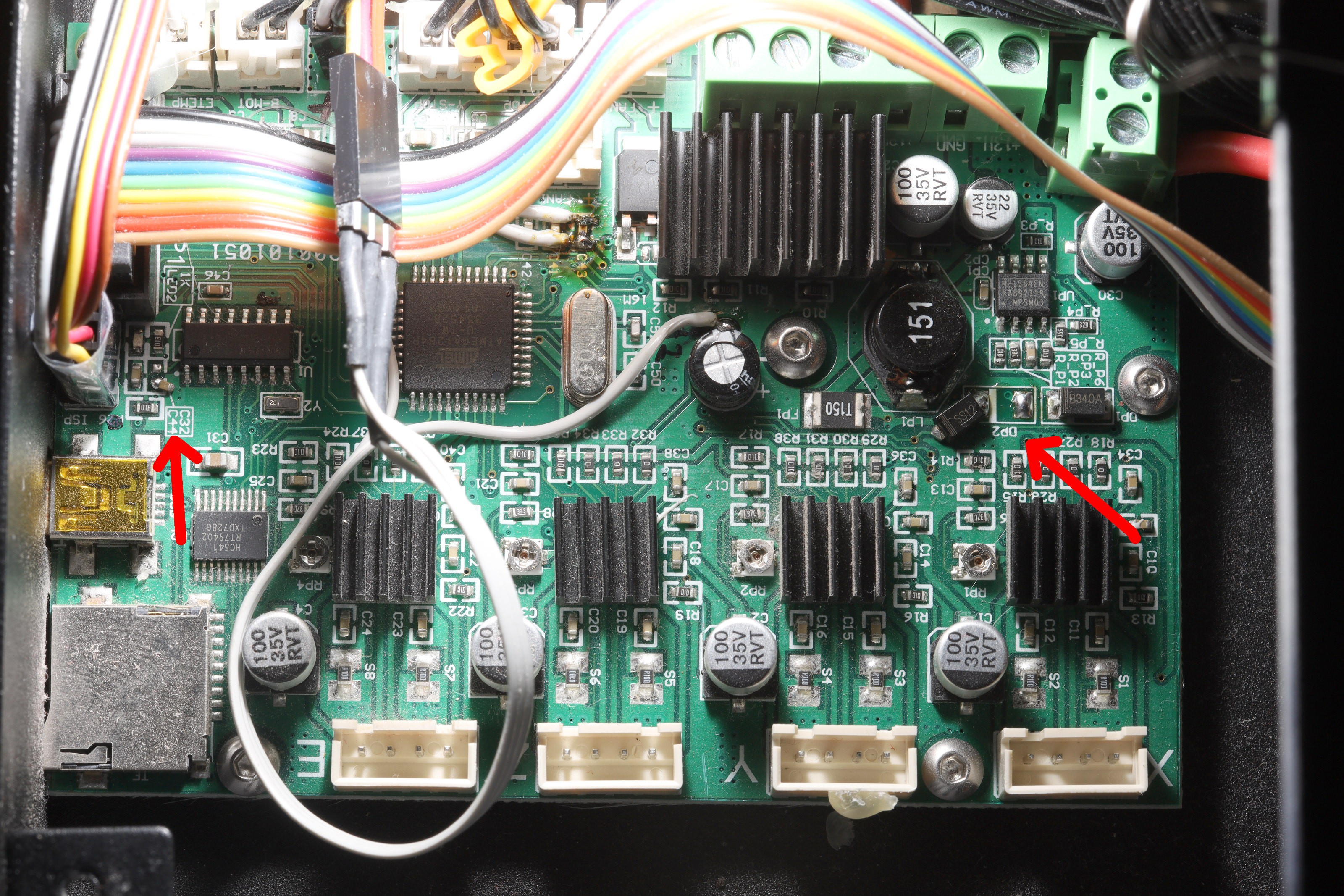
The catch is opening the USB serial port resets the atmega, destroying any print in progress. The way around this is to remove C32 from the board.
![]()
The other essential change is to unplug USB power from the mane board by removing DP2. Helas, the FTDI chip is powered by the mane board, not USB. These design flaws were undoubtedly kept from the board's Sanguino days.
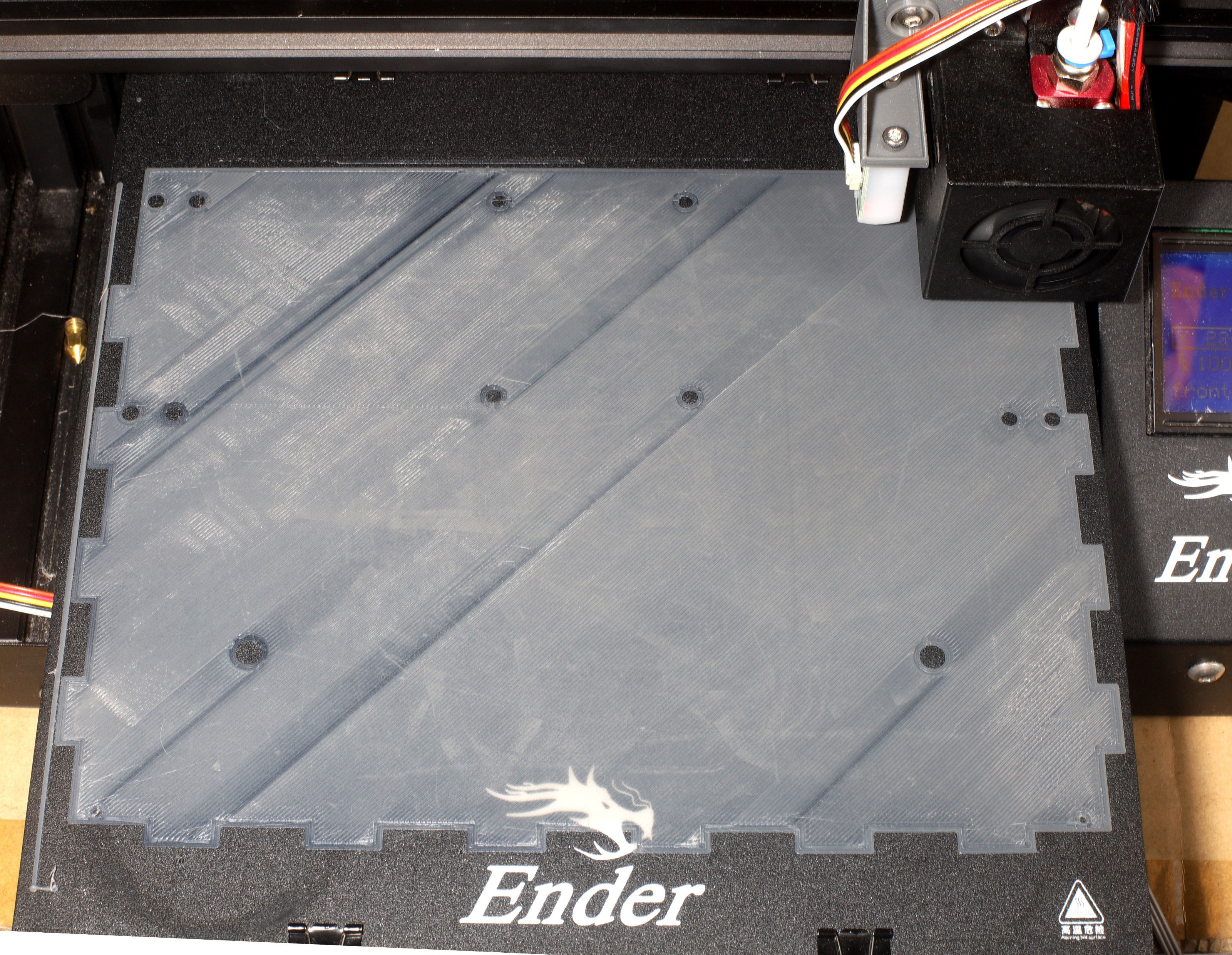
Large prints
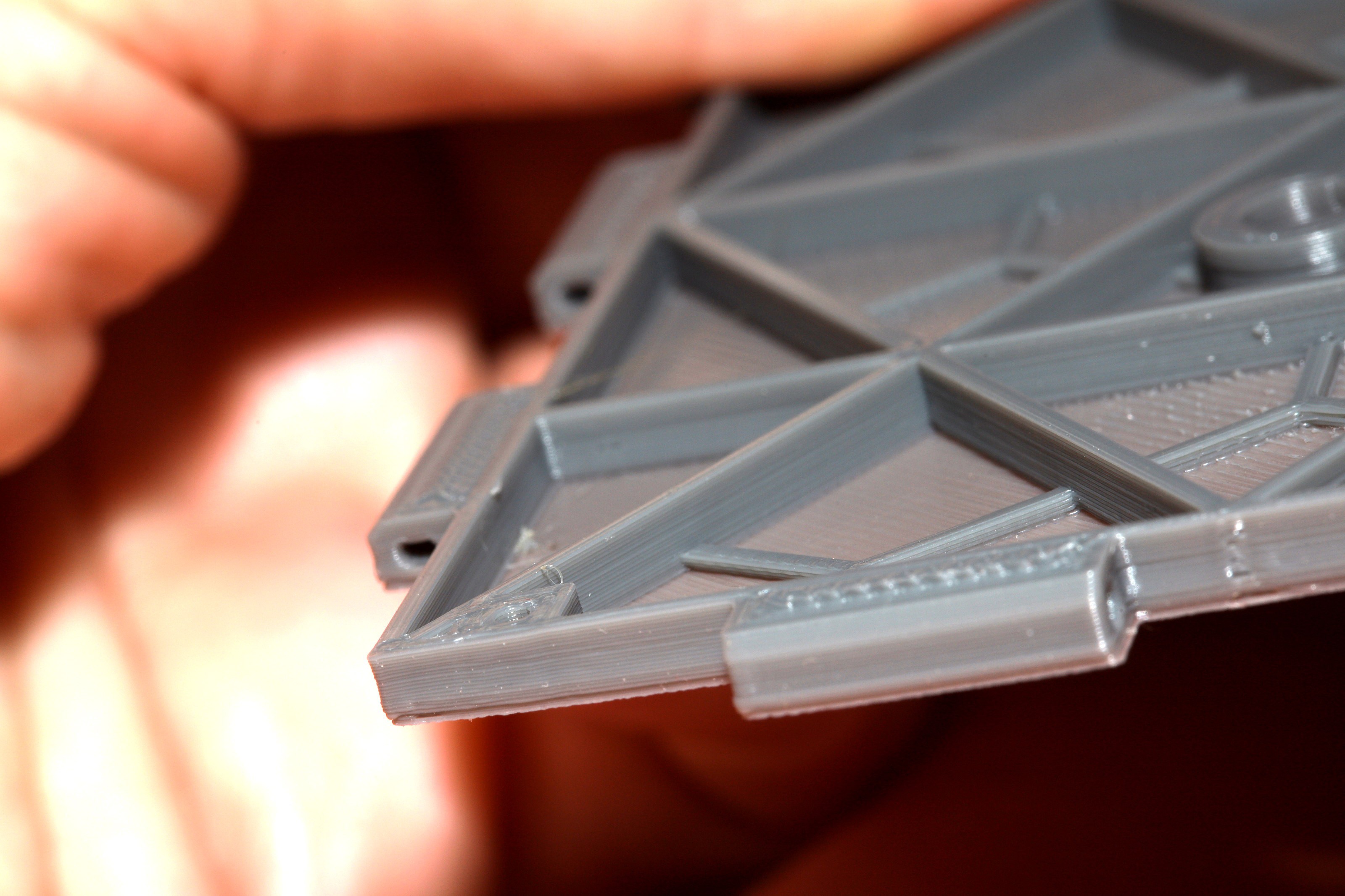
The lion kingdom has only 1 part which truly requires the full bed width & automatic bed leveling. Other narrower parts benefit from bed leveling but otherwise used to be printable with marginal quality.
![]()
With wide parts & automatic bed leveling, the heating becomes the limiting factor. They have to be as far left as possible. It can't print the right edge because of the lack of heating. Getting this wide required 65C for the 1st layer.
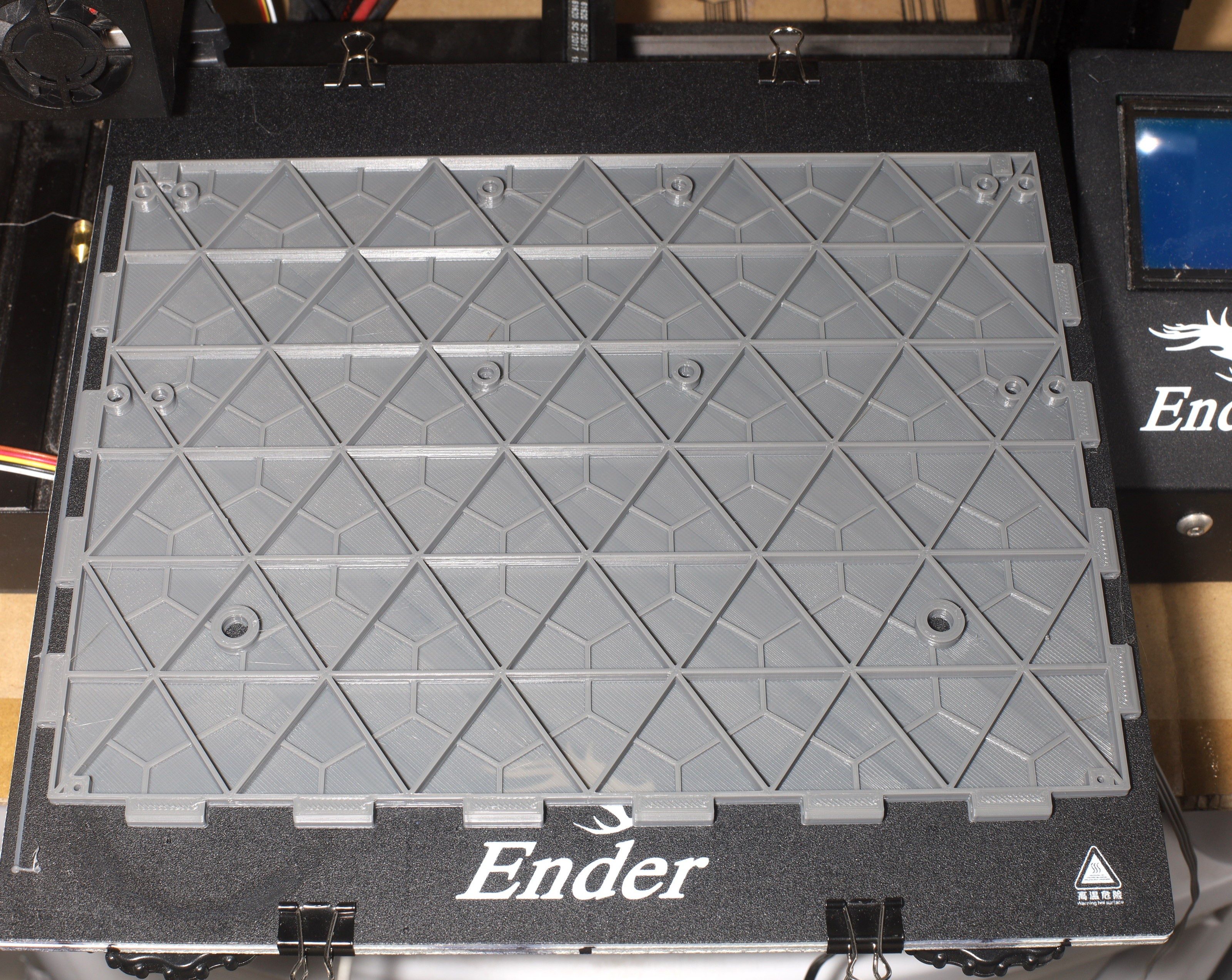
![]()
This part wasn't modeled based on the bed size, but it managed to fit by luck. 228mm is the practical limit of the 235mm bed width. It's not bad, considering the Ender 3 was marketed with a 220mm usable width.
![]()
![]()
Unfortunately, with wide parts you can't cool down the bed after the 1st layer. The shrinking of PLA becomes important. This part had its lower layers shrink & warp because the bed was cooled. You might get away with 65C for the bottom layer & 60C for the top layers.