0%
0%
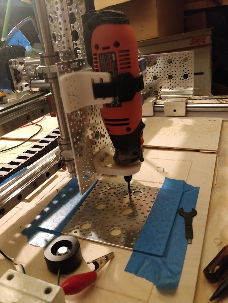
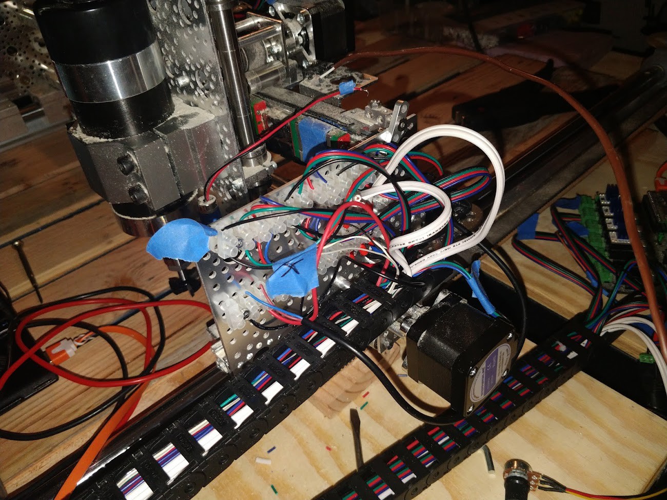
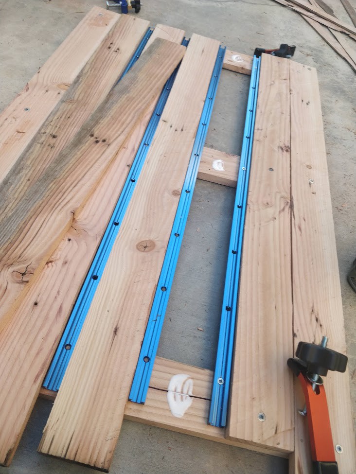
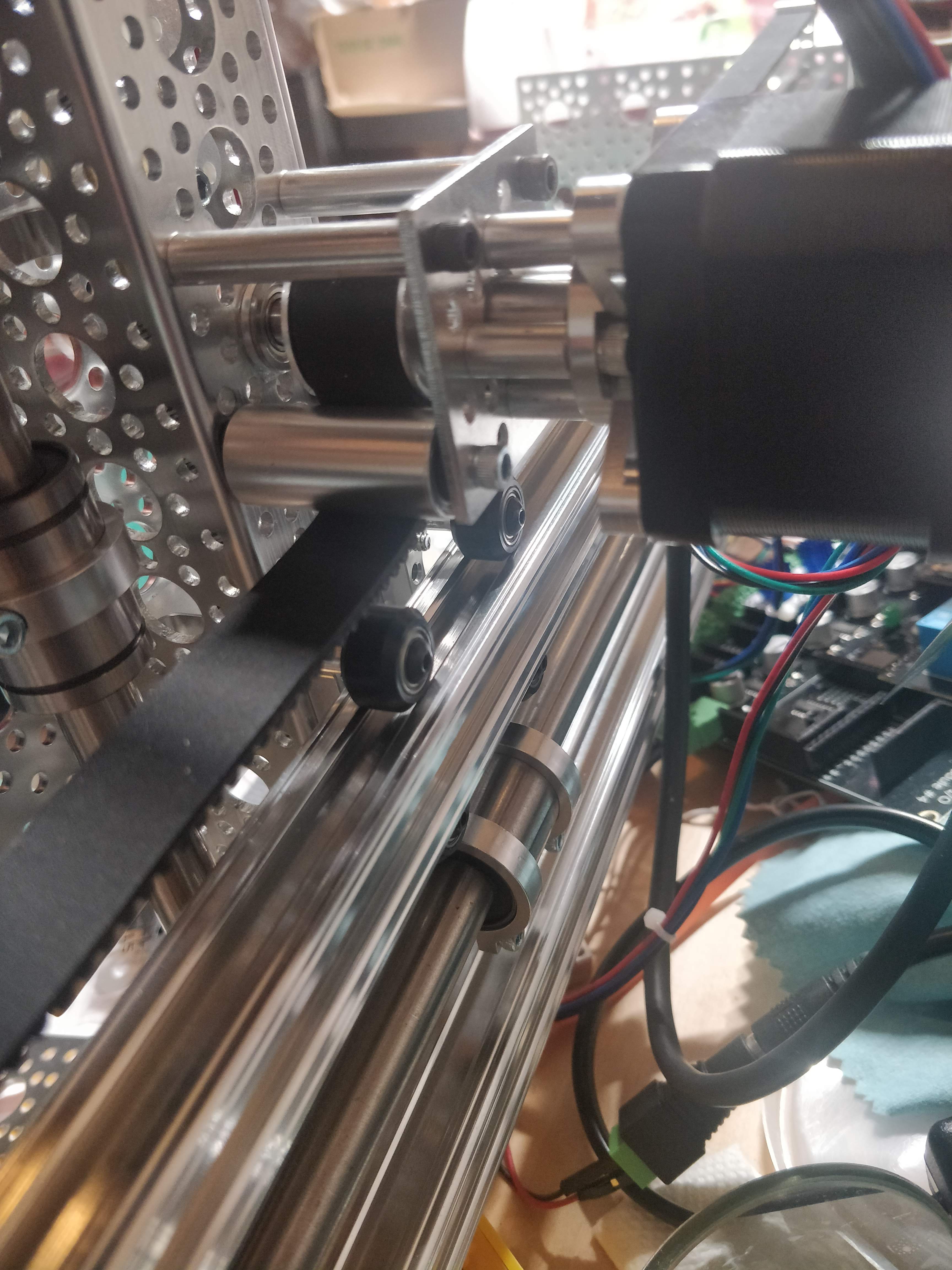
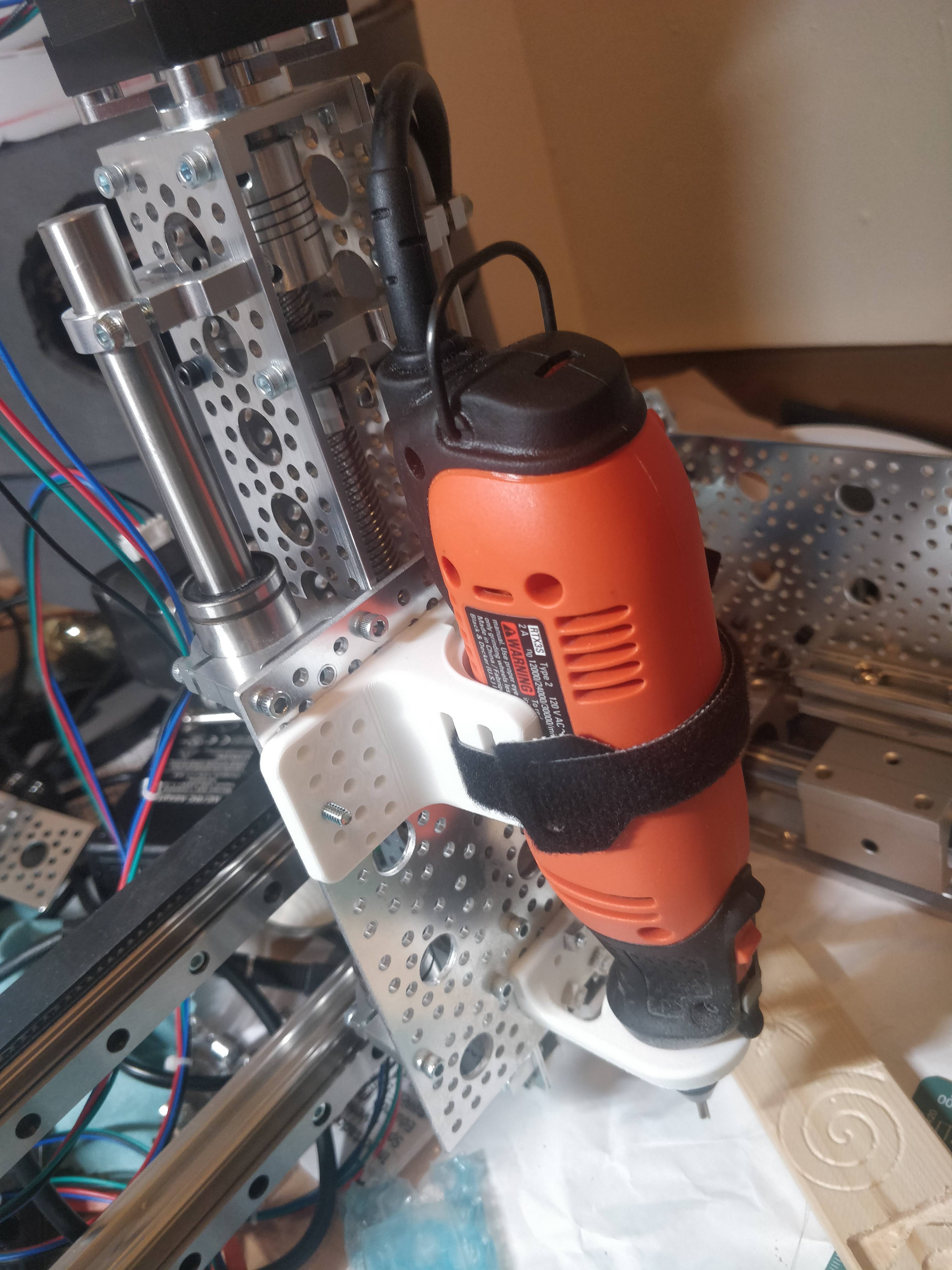
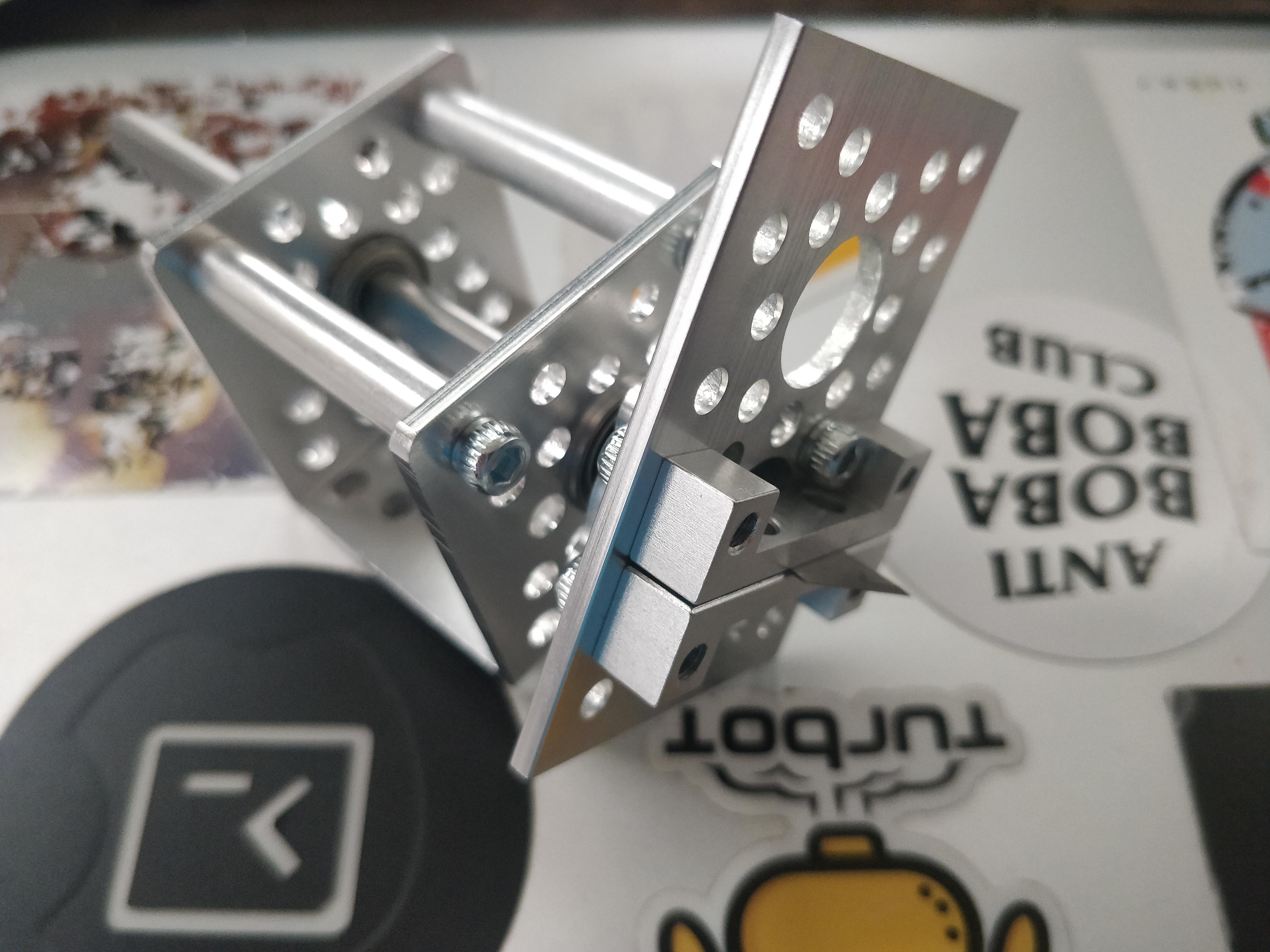
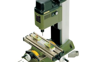
Homebrew CNC Experiments
Building a machine with mostly repurpose-able parts.
 Ted
TedBecome a Hackaday.io member
Already have an account? Log in.
Just one more thing
To make the experience fit your profile, pick a username and tell us what interests you.
Pick an awesome username
hackaday.io/
Your profile's URL: hackaday.io/username. Max 25 alphanumeric characters.
Pick a few interests
Projects that share your interests
People that share your interests

 dekutree64
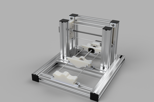
 Myles Eftos
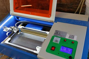
 Greg Duckworth
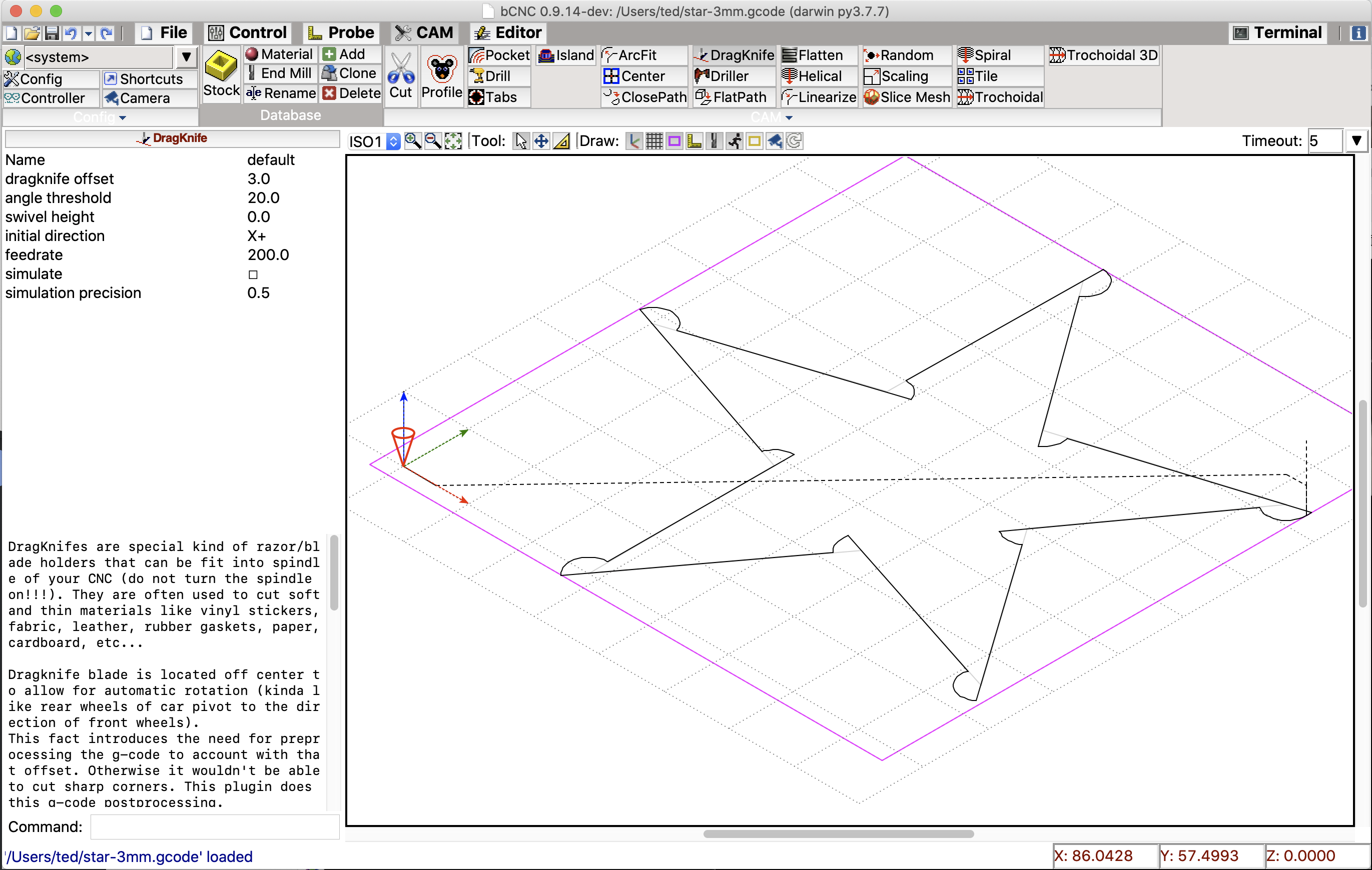
It depends on G-Code for what. For simple work and tweaking gCode, bCNC is very helpful.
For plotter, I haven't found something I really like yet - Inkscape gcodetools seems good but doesn't work at all some of the time.
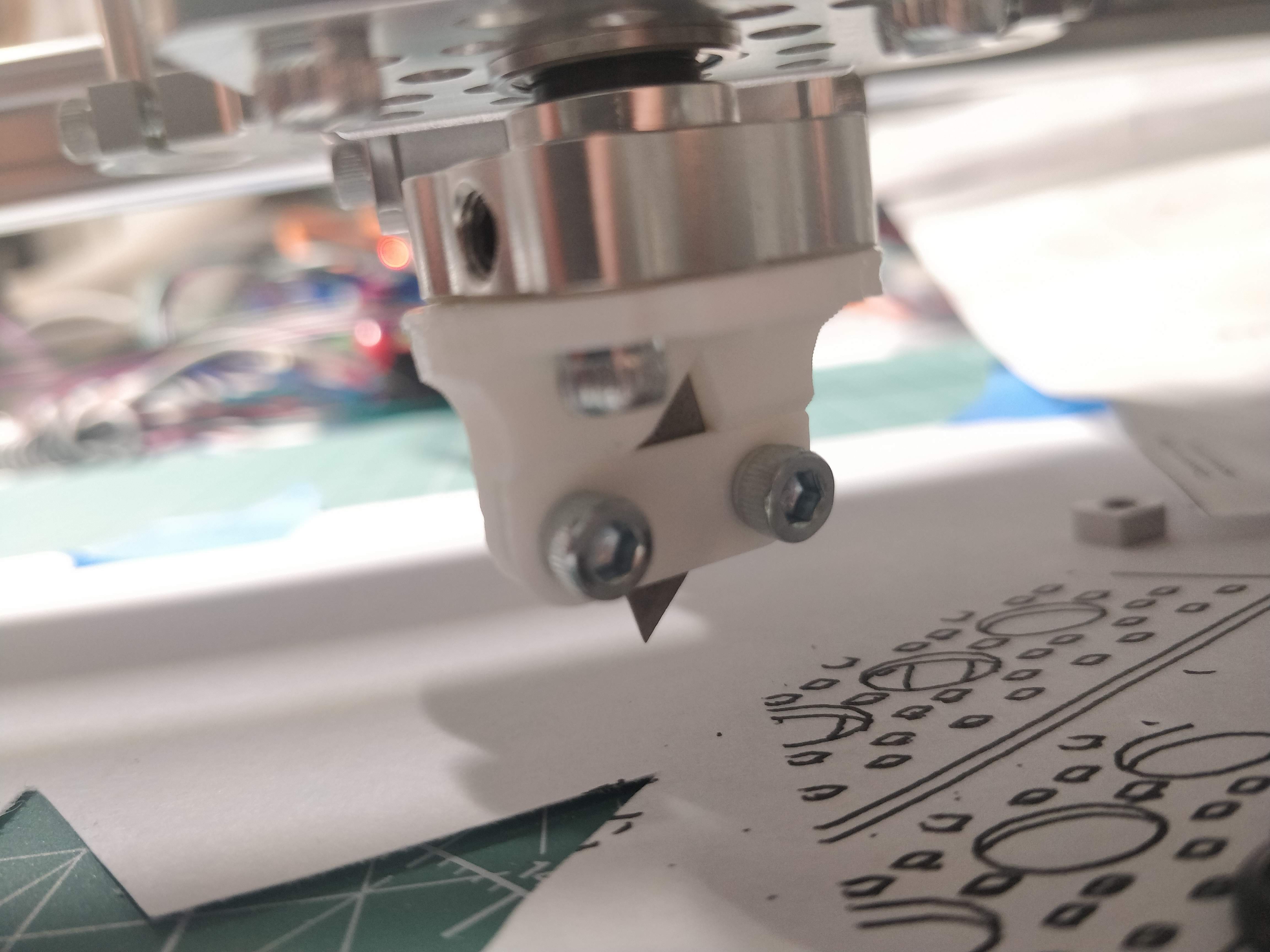
For drag knife, bCNC.
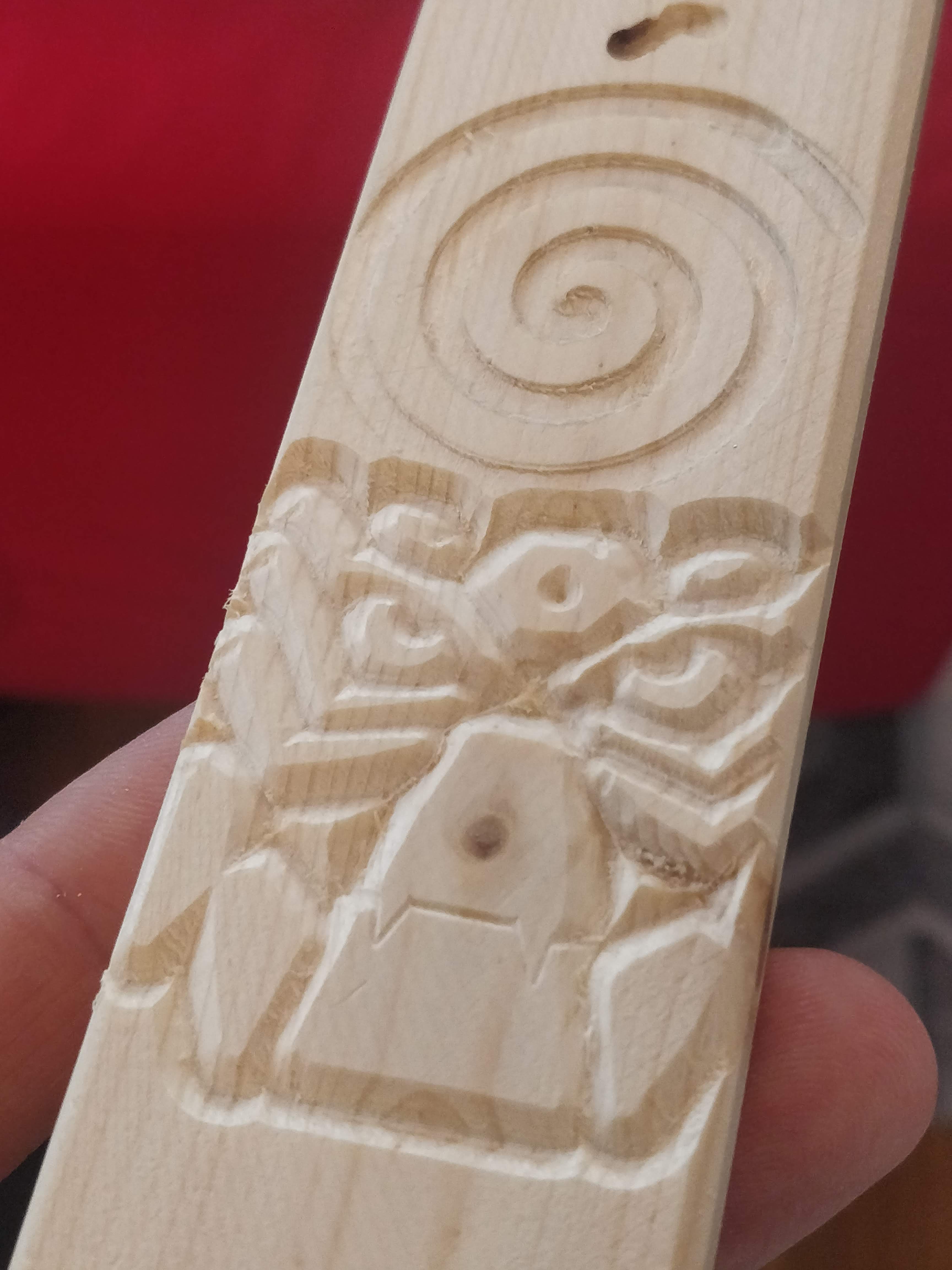
For V-bit engraving, F-Engrave.
For for advanced milling, FreeCAD. (I haven't tried Kiri:Moto yet, but that's an option too)