 Yann Guidon / YGDES
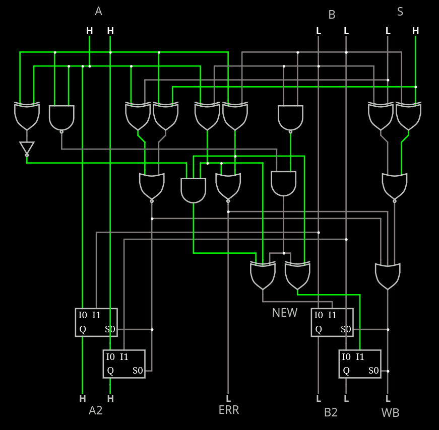
I'm starting to play with circuitjs. You can try a first playground here. It's still buggy and incomplete but you get the idea of the actual complexity.
For now I have dropped the requirement for B to avoid the 00 state, as well as the XOR. When the circuit detects A=B, it outputs an "error" status bit and forces the update: this makes the circuit self-correcting after a couple of cycles, like the old 4017.
This changes the boolean equations that I already found the other night, and I must redesign them. There are only 64 cases to consider, with many possibilities, but few are minimal.
The following lookup table shows the values injected into B, since A is usually a copy of the old B.
      |  S:
A: B: |  00        01        10        11
------+-----------------------------------------
00 00 |  R:01,10,11...........................
00 01 |  A:10,11   B:10,11   x         x
00 10 |  A:01,11   x         B:01,11   x
00 11 |  A:01,10   x         x         B:01,10

01 00 |  B:10,11   A:10,11   x         x
01 01 |  R:00,10,11...........................
01 10 |  x         A:00,11   B:00,11   x
01 11 |  x         A:00,10   x         B:00,10

10 00 |  B:01,11   x         A:01,11   x
10 01 |  x         B:00,11   A:00,11   x
10 10 |  R:00,01,11...........................
10 11 |  x         x         A:00,01   x

11 00 |  B:01,10   x         x         A:01,10
11 01 |  x         B:00,10   x         A:00,10
11 10 |  x         x         B:00,01   A:00,01
11 11 |  R:00,01,10............................

x : no modification
R: error (A=B) =>      B=new (A=B implicit, harmless)
A: Match A     => A=B, B=new
B: Match B     =>      B=new
In all cases, the output A is either input_A or input_B. So there is nothing to compute on this part.
The only thing to compute is the new_B : 2 bits depending on 6 input bits. Make it 7 for the random input. And an 8th input for MRU mode but it doesn't affect the computation of new_B. And the table shows that the possible outputs only depend on the A and B inputs (4 bits only).
Condensed array:
A: B: A^B |  Possible values:
----------+------------------
00 00  00 |     01,10,11
00 01  01 |        10,11
00 10  10 |     01,   11
00 11  11 |     01,10

01 00  01 |        10,11
01 01  00 |  00,   10,11
01 10  11 |  00,      11
01 11  10 |  00,   10

10 00  10 |     01,   11
10 01  11 |  00,      11
10 10  00 |  00,01,   11
10 11  01 |  00,01

11 00  11 |     01,10
11 01  10 |  00,   10
11 10  01 |  00,01
11 11  00 |  00,01,10
All entries have at least 2 possible outputs, to be selected by a random bit.
The possible outputs must not be A or B so A^B is a very interesting value.
The table shows that ~(A^B) is a valid value for most entries except for B=11, where A^B is valid, so we have something here! A NAND and a few XOR will work.

It seems that my initial boolean analysis was wrong.
A: B: A^B /A^B |  Possible values:
---------------+---------------------
00 00  00   11 |     01,10,11
00 01  01   10 |        10,11
00 10  10   01 |     01,   11
00 11  11   00 |     01,10

01 00  01   10 |        10,11
01 01  00   11 |  00,   10,11
01 10  11   00 |  00,      11
01 11  10   01 |  00,   10

10 00  10   01 |     01,   11
10 01  11   00 |  00,      11
10 10  00   11 |  00,01,   11
10 11  01   10 |  00,01

11 00  11   00 |     01,10
11 01  10   01 |  00,   10
11 10  01   10 |  00,01
11 11  00   11 |  00,01,10
There is obviously a requirement to use a "diagonal" of the squares (even permuted) because focusing on a column would create an unacceptable bias of the sequences, particularly if 11 is constantly output (except 00 when A=11). So both bits should be inverted when A!=11.
But there is more happening with B=11 that requires special care.
In the new circuit, A=00 B=11 and A=11 B=00 both resolve to the unwanted value 11.
For A=00 B=11 this creates the forbidden state 11 11 when the desired set S is also 11. This case is only 1/4th and the result can later be recovered because the next state will become 11 00. Adding an extra gate can avoid the copy of B into A2.
For A=11 B=00, the forbidden state 11 11 is also output when S=00.
A few more gates (A[0] xor A[1], NAND3 and XOR3 replacing XOR2) solves this and we get :
- A=00 B=11 S=00 => A2=11, B2=01
- A=11 B=00 S=11 => A2=00, B2=01
And that's it.
A: B: | value:
------+---------
00 00 |  11
00 01 |  10
00 10 |  01
00 11 |  01
01 00 |  10
01 01 |  11
01 10 |  00
01 11 |  10
10 00 |  01
10 01 |  00
10 10 |  11
10 11 |  01
11 00 |  01
11 01 |  10
11 10 |  01
11 11 |  00
The map is slightly biased toward 01 but that's fine.
- 00: 3×
- 01: 6x
- 10: 4×
- 11 : 3×
I'm sure there are some other ways to implement this, depending on the technology. I tried to minimize the number of gates but the bias towards 01 is reduced with one more gate or two.
Anyway you can play with it at home.
Discussions
Become a Hackaday.io Member
Create an account to leave a comment. Already have an account? Log In.