Matthew Begg
-
Back to basics...no soldering required?
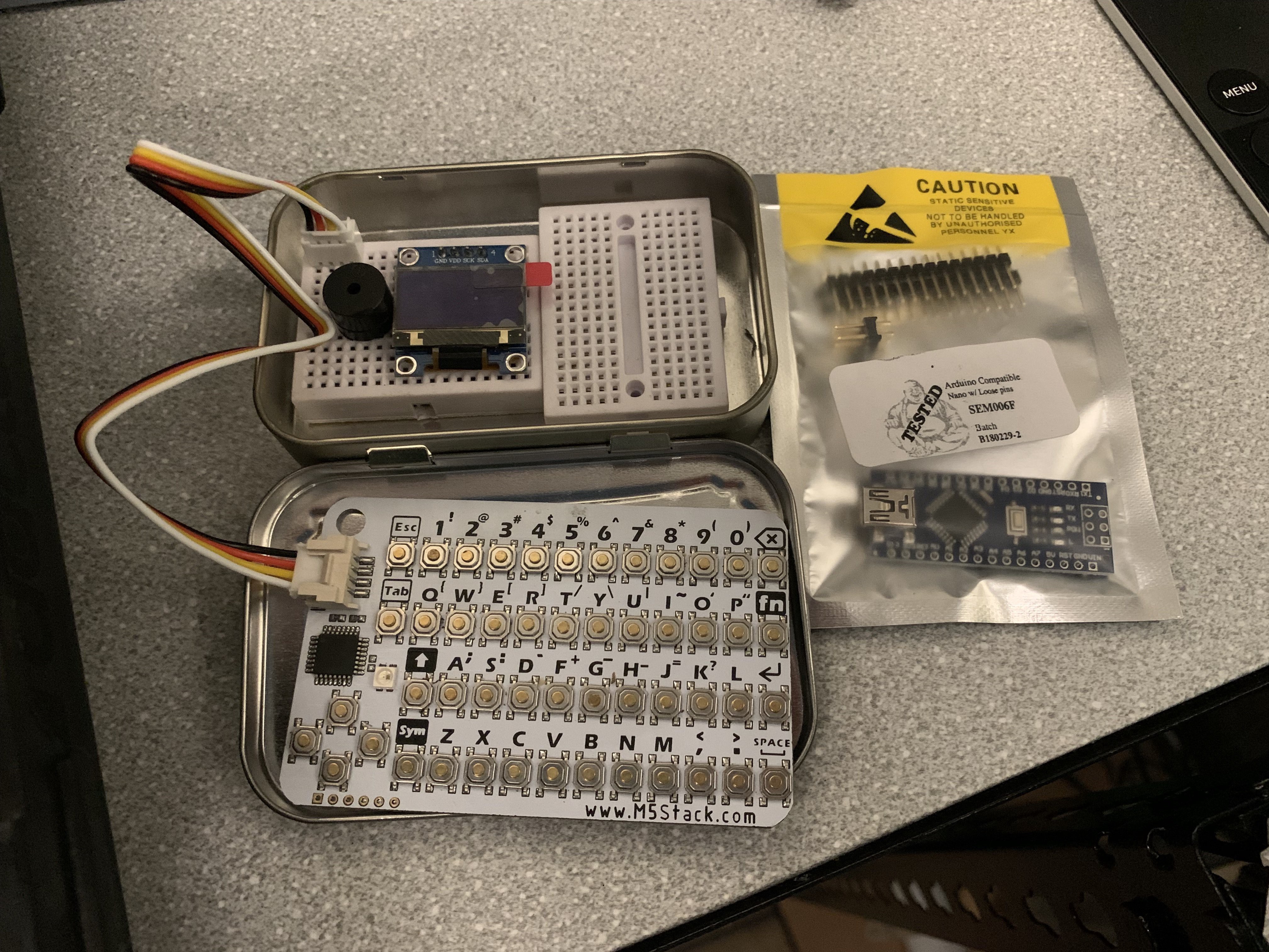
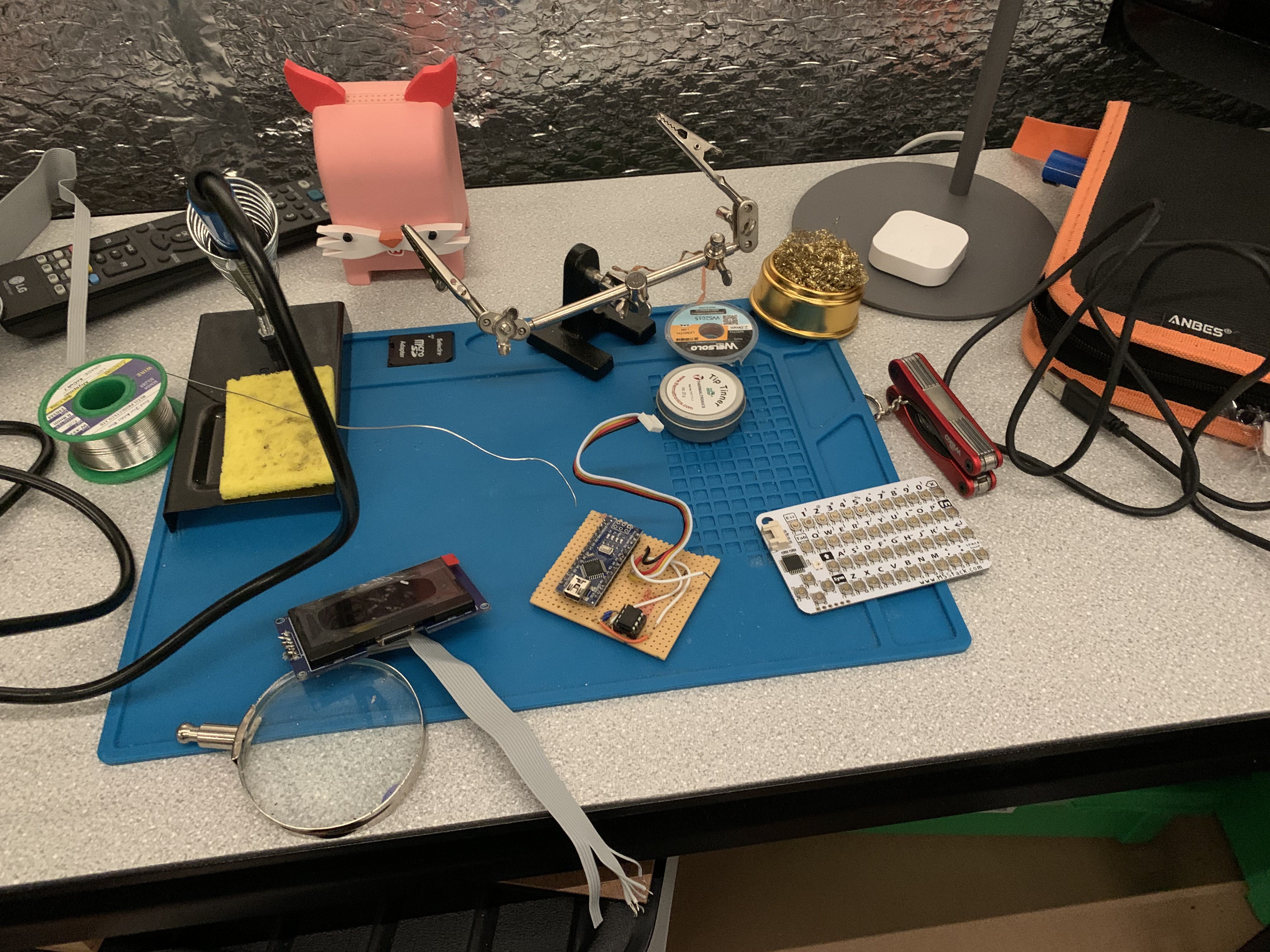
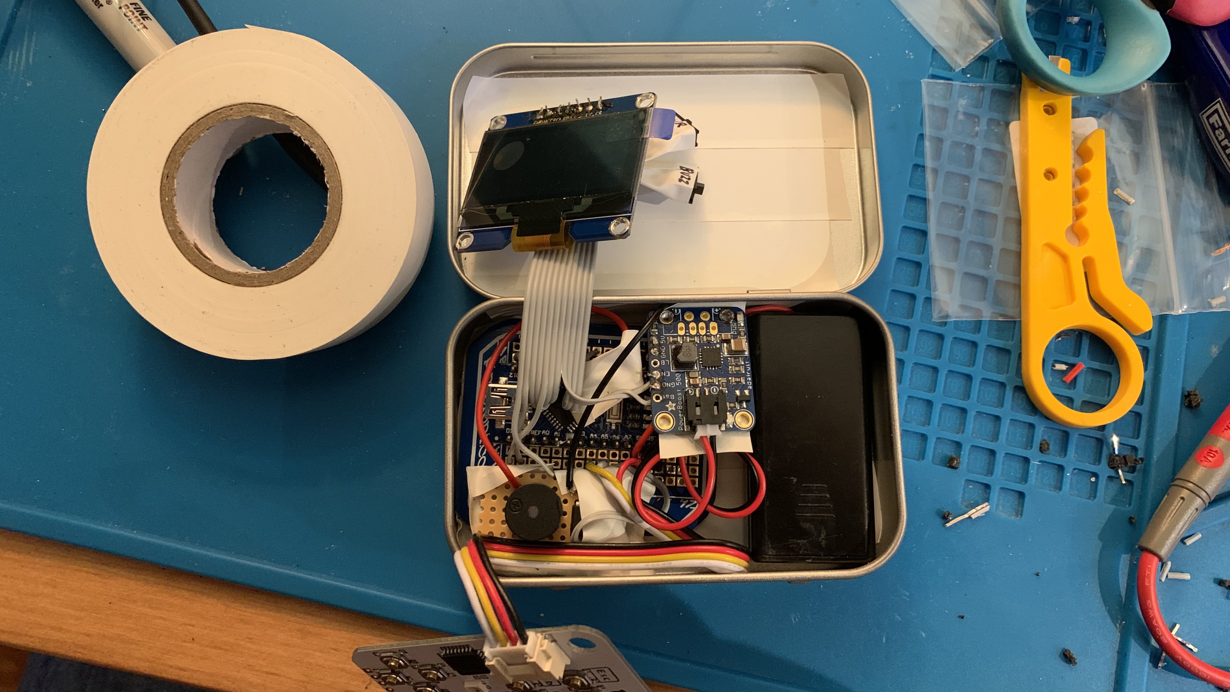
07/18/2022 at 22:04 • 1 commentDespite being distracted by other projects (including the eMBee TWO with colour screen), I keep being drawn back to the simplicity of the eMBee ONE and the 8-bit aesthetic. One aim is for this to be a simple project for anyone to build. Perhaps it would be possible to build this (and fit it inside the Altoids tin) WITHOUT soldering? I did some initial research into this idea, and it looks possible. The image below shows a real Altoids tin (cinnamon flavour if you must know!) with two small solder less breadboards inside. I've placed the display, keyboard connector and buzzer but didn't have an Arduino Nano with headers attached. You can see a fresh unheadered one in a bag there. But you can buy them from eBay and AliExpress with headers already attached. So this is looking very promising. Still begs the question of how to power it and still have it all fit in the tin. Also can the innards be made tidy once the hotchpotch of jumper wires are attached?
![]()
Couple of issues to consider:
- The PCB connector for the Grove cable (from the CardKB keyboard) isn't the correct pitch for a breadboard. I've had to bend the pins a bit and although I think it works, it's not a very stable connection. A slight knock and it comes out.
- I haven't settled on the orientation of the two mini breadboards
- The location of the keyboard connection will affect how easily the lid closes
- I've gone back to the ubiquitous 0.96 inch 128 x 64 OLED mainly for cost and size reasons. I know it isn't as eye-catching as the 2.42 inch display but it's a lot more affordable and keeps the rest of the components visible.
What do you think to this slight change in direction towards non-soldered kits?
-
eMBee ONE update - all working but doesn't fit
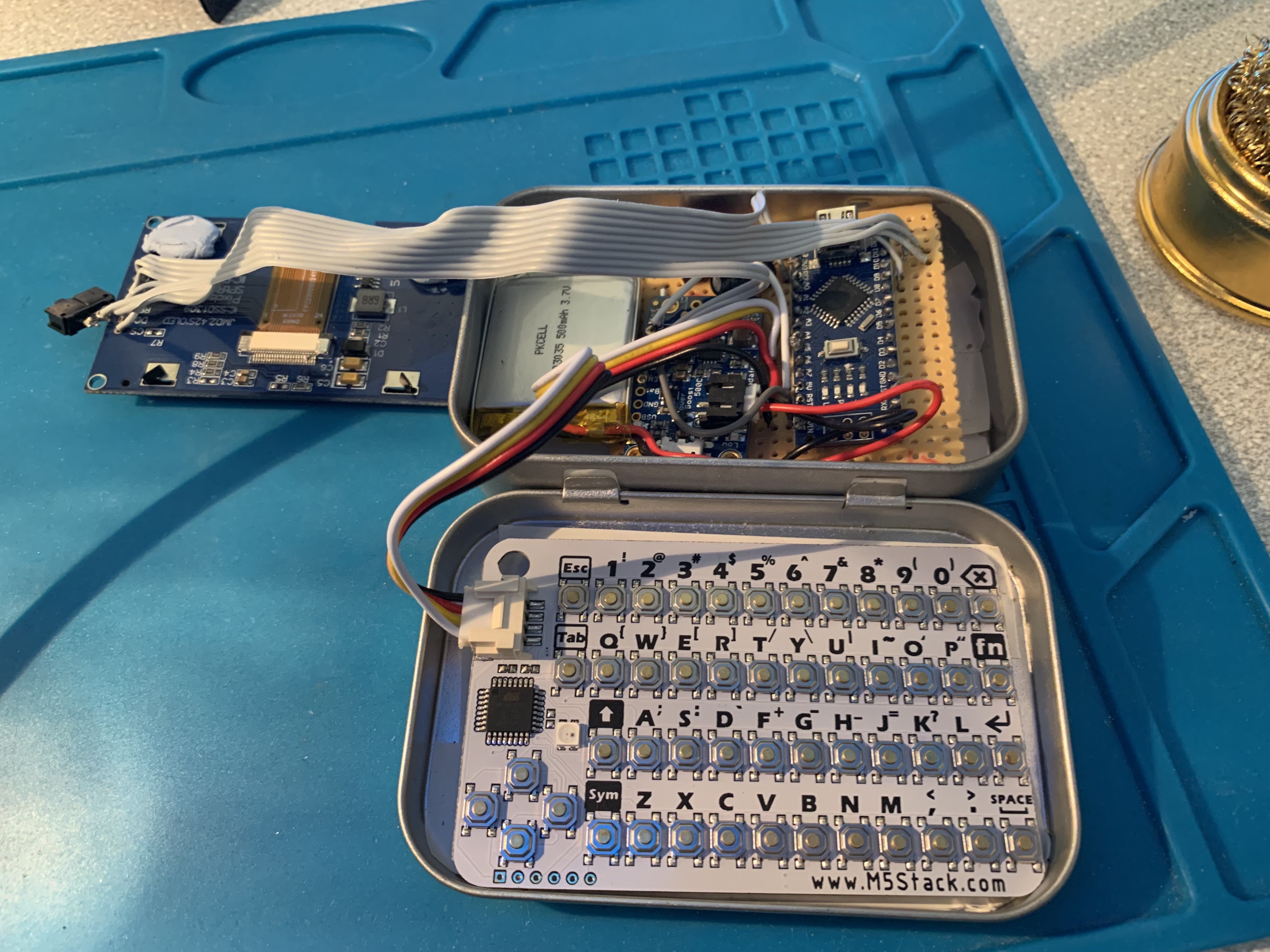
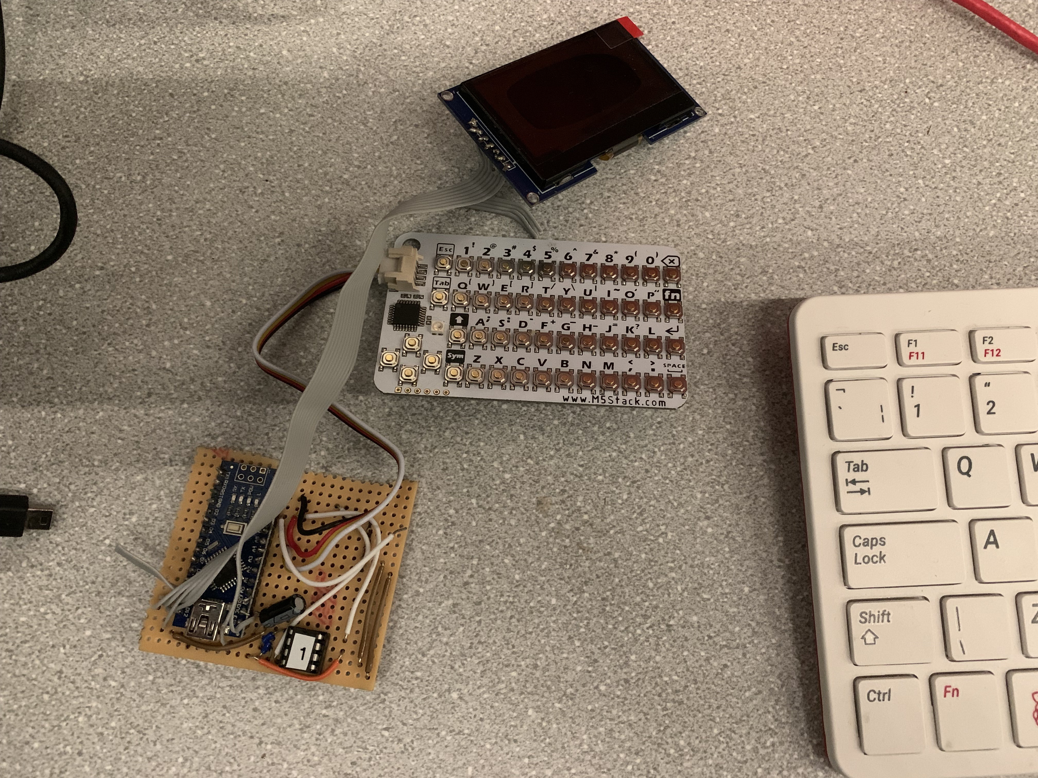
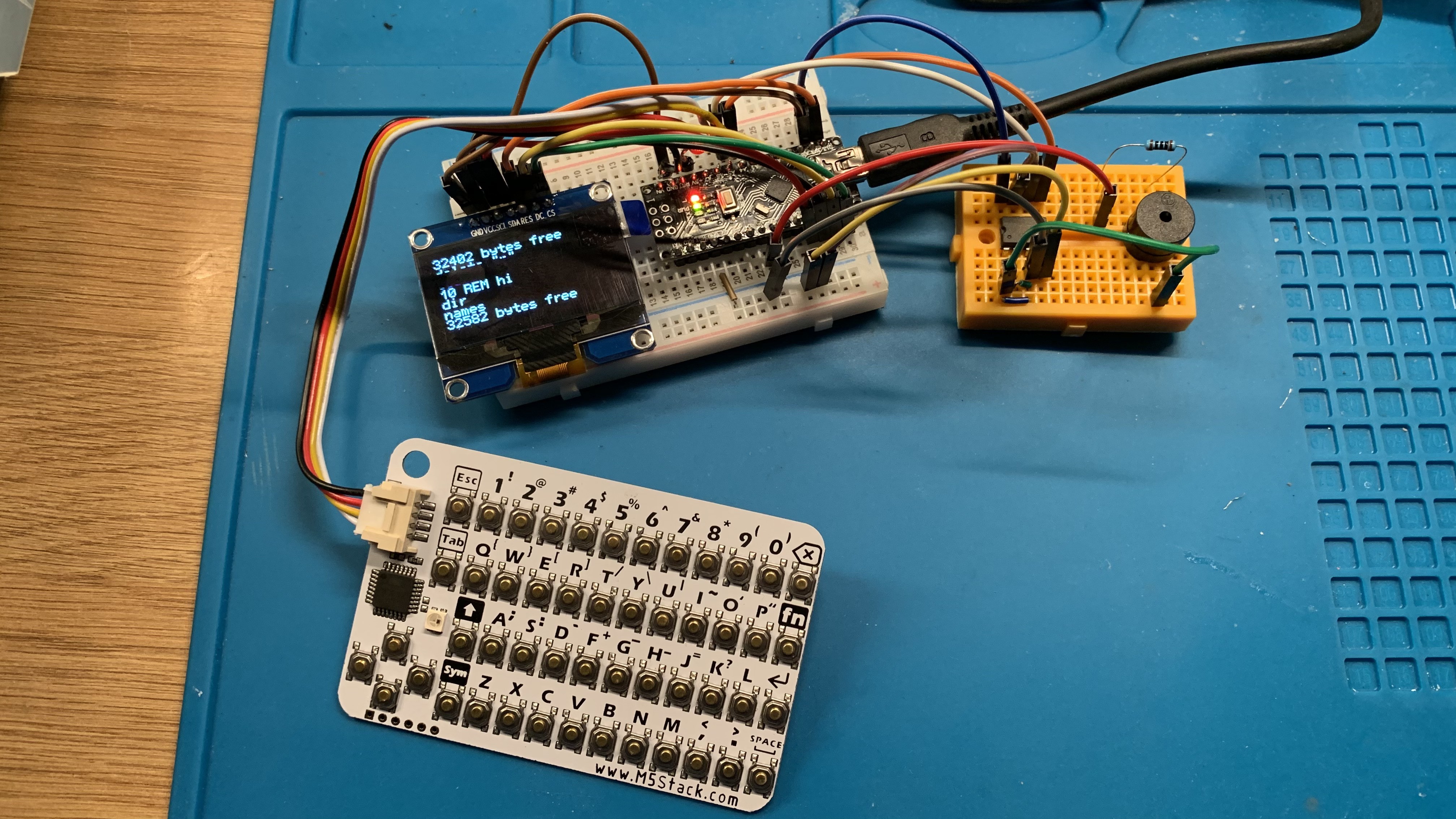
03/12/2022 at 15:34 • 0 commentsSorry for the long pause in log entries - I actually had everything working a couple of months ago. So it now has a lipo battery connected, and can operate standalone in the tin. However, I had made the ribbon cables for the keyboard and display too long, which means they take up too much space in the tin and the lid doesn't close. Look how long they are:
![]()
What this image also shows you is my new plan for swapping everything around in the tin. So the keyboard is now in the lid, and the screen joins the main board in the main part of the tin. There are a few reasons for this, but mainly so typing is more comfortable, with a solid surface to type on rather than putting pressure on the other components every time you type something.
As I started to chop the wires down, my soldering iron bit broke in half! Then had to wait for it to cool down before replacing it. And that's when my brain started wandering into the possibilities of designing a custom PCB, using cheaper but more powerful hardware...
Introducing the eMBee TWO!
I'm still planning to finish the eMBee ONE as a one-off piece (just a few wires to shorten so the lid closes), but if you want to build a pocket computer that boots into BASIC, then the eMBee TWO will be the project to follow.
Thank you to everyone who followed the project, and I hope to see you for the next generation of the eMBee platform!
-
It's aliiiiiive!
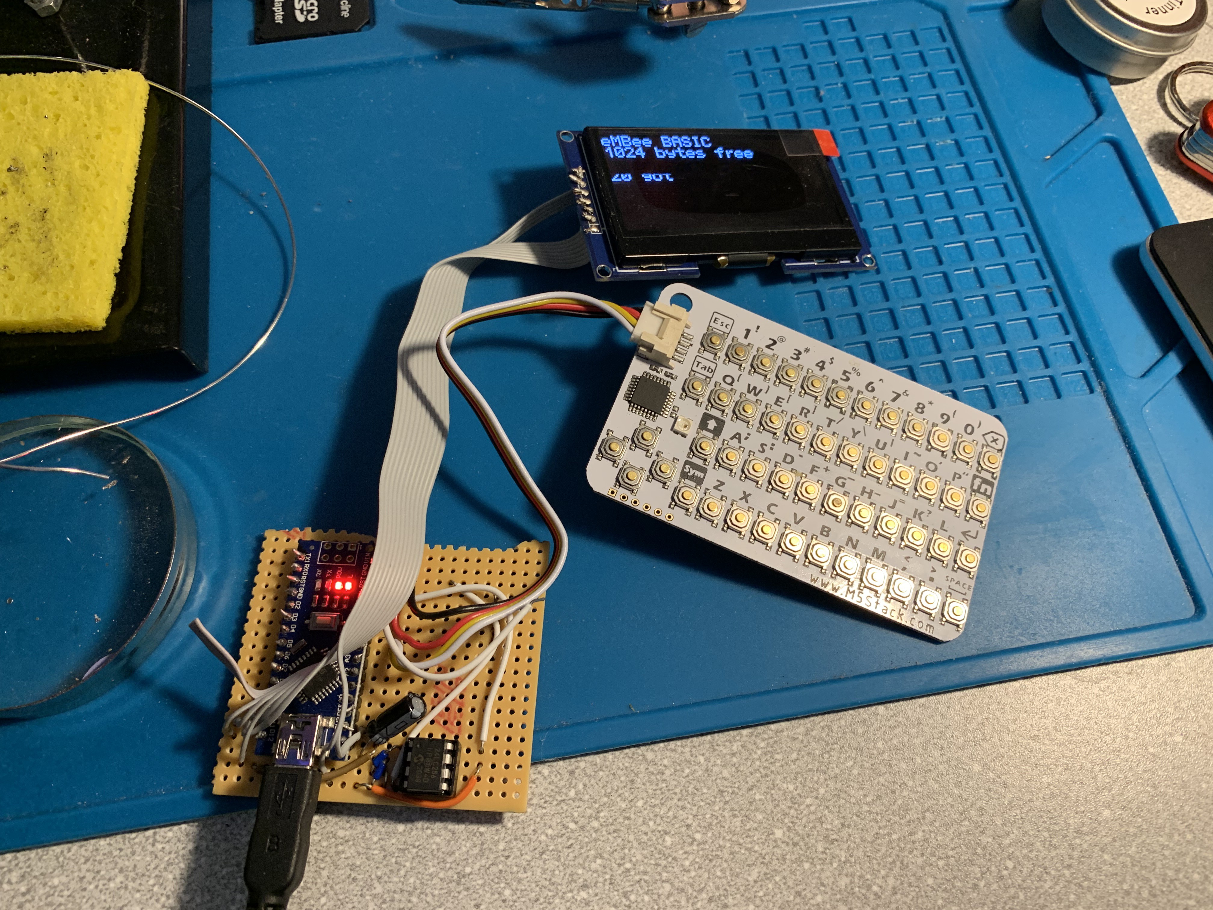
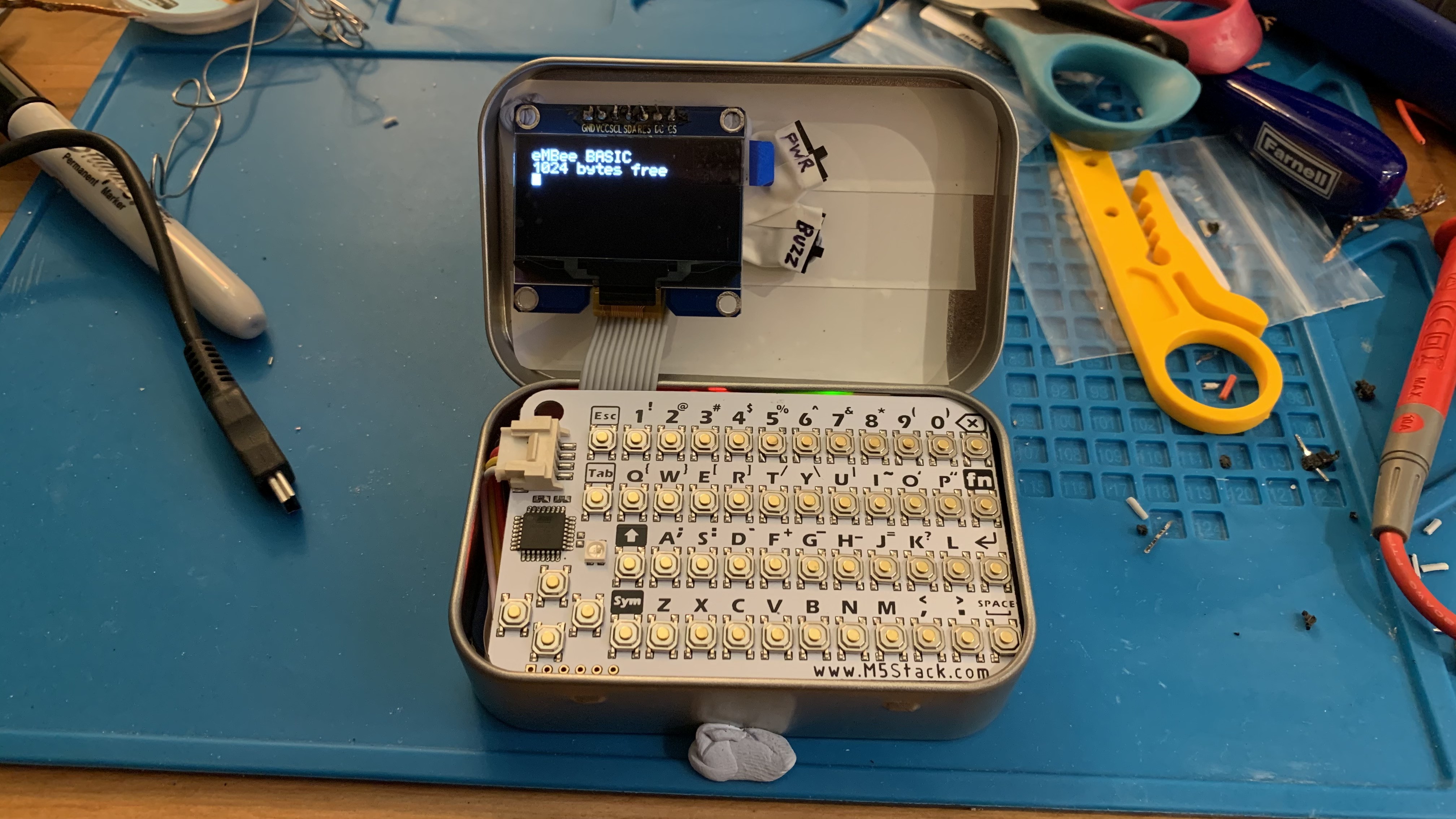
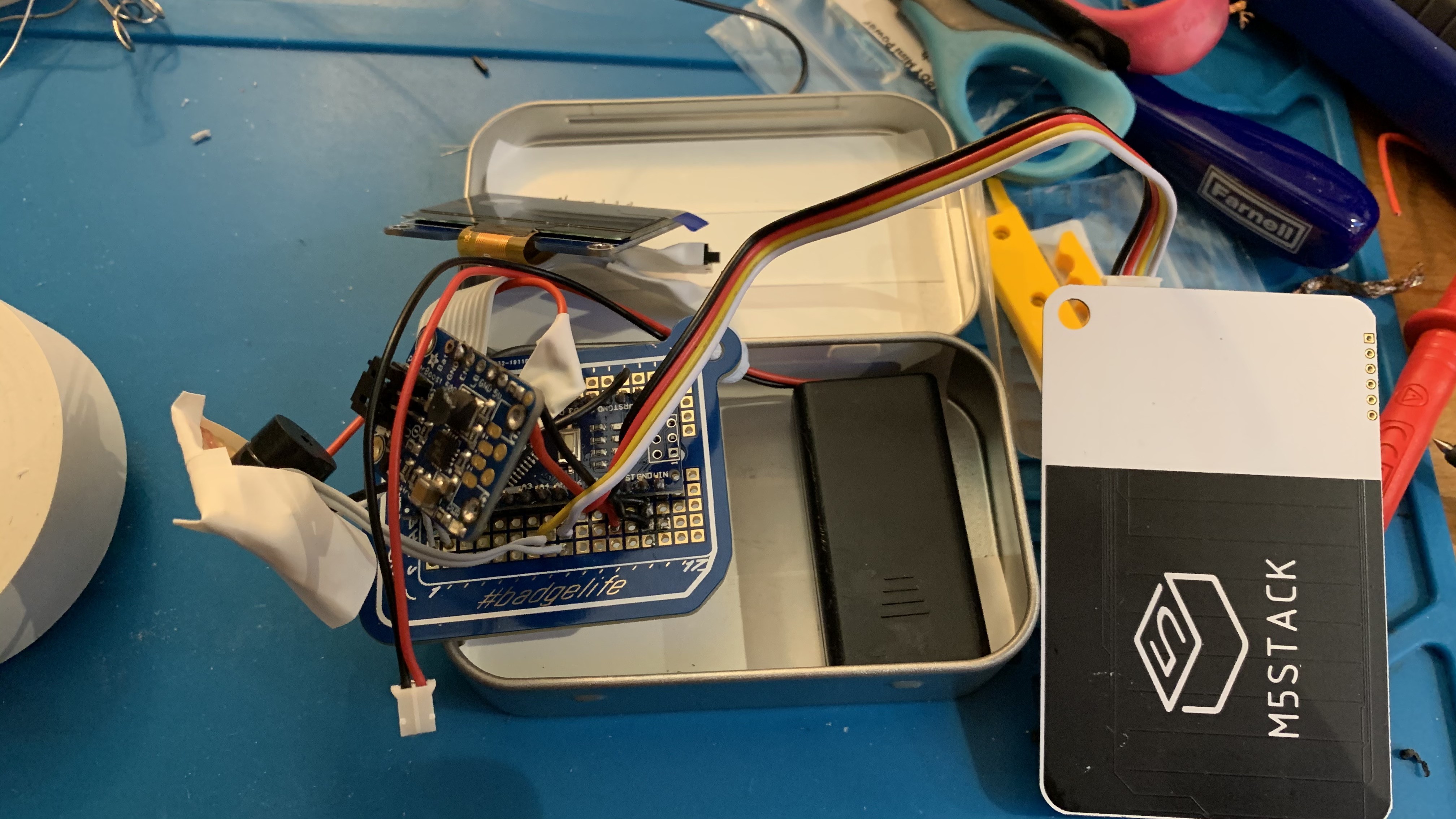
10/28/2021 at 22:21 • 0 commentsI finished connecting the 2.42 inch OLED display to the board. One difference this time: I added a 47uF capacitor across the 3.3v and GND to hopefully stop the display from dimming. And it appears to work!
So the display, keyboard and BASIC are working. Currently just powered via the Nano's mini-USB socket. Still to come:
- External EEPROM (you can see it in the pictures but I need to 'reformat' the chip before it'll work properly)
- Buzzer (maybe switching to a flatter disc-type piezo sounder to take up less space in the tin)
- Power circuit with LiPo
- Possible switches for power and sound
- Fitting it all in the tin
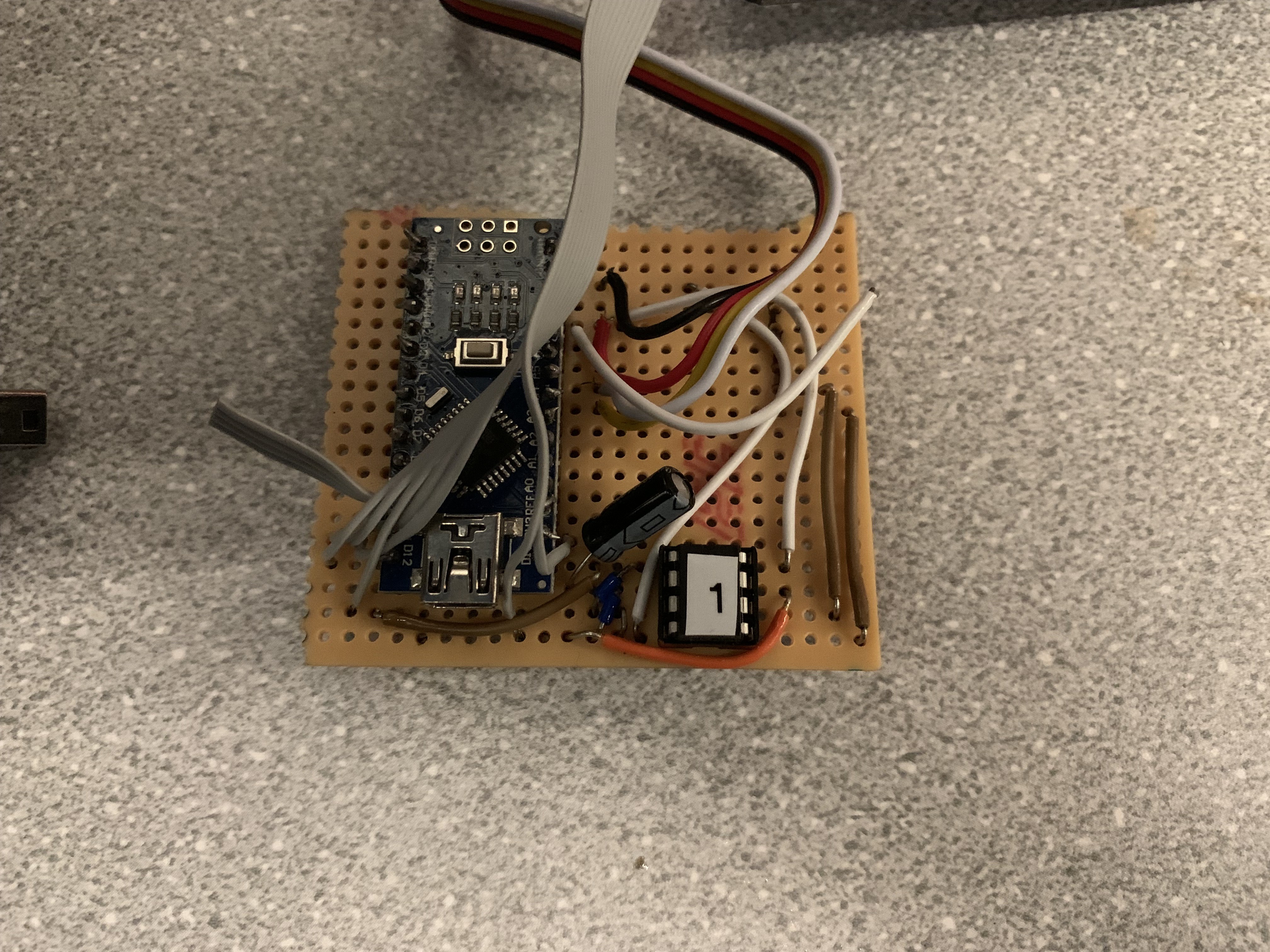
So plenty to do! In the meantime, here are some images...
![]()
![]()
![]()
-
Return of the eMBee ONE
10/17/2021 at 17:55 • 0 commentsFinally got back in the shed and got the eMBee ONE project back on track. Soldered the new 2.42 inch OLED display onto the (longer) ribbon cable.
![]()
Next step will be getting it running again before assembling the new power circuit and lipo battery.
-
All quiet at eMBee HQ!
03/22/2021 at 09:45 • 0 commentsHi all,
Just a quick update as you haven't heard from me in a while. Since the last update, I have started to move the project to a single veroboard/stripboard design, still using an Arduino Nano module, CardKB keyboard, 24LC256 EEPROM etc. But because I've changed my mind so much in the past, I've ended up struggling to desolder various pins and wires from each module (particularly the 1.54 inch OLED and the Adafruit PowerBoost). So I thought to make it easier, I'd order another screen. Which made me debate going back to the 'big' 2.42 inch OLED or stick with the 1.54 inch. You'll remember that my previous 2.42 inch display kept dimming at random intervals. But I'm assured that isn't expected behaviour and it must've been a faulty unit. So I have reluctantly ordered another 2.42 inch display from eBay. Will take about a month to come, so not much will happen with the project until it arrives. But then it should be full steam ahead with a new final unit being prepared, and the 3D printed parts being designed. Exciting!
Previous comments on this project have included suggestions of various features to be added, which go beyond my original vision. Let me know in the comments below if you think I've got the balance right between simplicity, nostalgia and features.
-
The first prototype!
02/19/2021 at 10:35 • 0 commentsHello world!
Here is the first prototype of the eMBee ONE. Hand soldered, self-contained, and running from 2 x AAA rechargeable batteries. More pictures:
![]()
![]()
![]()
A few things to note:
- The screen is not where I wanted it to be. The idea was to have it centrally in the top lid, but I accidentally cut the ribbon cable too short, so it wouldn't reach.
- Two switches to the right of the screen: 'PWR' connects the 'EN' and 'GND' of the Adafruit PowerBoost to act as a main power switch. 'BUZ' is to switch the buzzer off/on.
- Fitting all those separate modules and prototyping boards into the bottom case is a tight squeeze. Future versions will definitely have the modules all on one prototyping board to make it thinner.
- The lid doesn't close. Partly because the screen is too far left and hits the CardKB GROVE connector, and partly because the modules are all separate and are too tall.
- When typing, the keyboard bends in certain places as it isn't supported underneath.
- The eagle-eyed among you will spot I forgot one connection - the VCC for the external EEPROM, so it currently can't access the 32KB of storage. However it's just a simple wire for that to work.
Demo program
Conclusion
Really pleased with this first prototype - it just about proves the concept works. And, as with all good prototypes, it shows me what needs to happen next:
- Use a custom-sized piece of prototyping board and attach the Nano, PowerBoost, EEPROM and buzzer to it. A single board will help with the space in the bottom half.
- Use a longer ribbon cable for the display so it can be placed centrally.
- The lid should close.
- Once the second prototype is working, my cousin can provide the 3D printed bezel for the top, and perhaps a 3D printed support structure to stop the keyboard bending while typing.
Let me know what you think in the comments below!
-
Project update
02/09/2021 at 14:03 • 0 commentsPrototype coming soon
So I'm pretty close to having a rough prototype working. This will use an Arduino Nano, PowerBoost 500 Basic, CardKB keyboard, SPI OLED screen, piezo buzzer and 2xAAA batteries. Hoping to get that all soldered together and working in the tin this week. My idea of using mini breadboards isn't feasible due to the size constraints of the Altoids tin.
That then begs the question: do I encourage people to build the same thing from all those modules? Or do I create a custom PCB using an ATMega 328P chip and make a single-board version to replace the Nano and PowerBoost?
3D printed bezel
My cousin has very kindly offered to design and build a 3D printed bezel to mount the OLED screen nicely in the top of the tin. Once finalised, we will make the files for that available here.
Comments
Thanks to everyone who has commented so far in the discussion section below. Lots of nice comments and suggestions. Some people seem to want this computer to do more. For that, I'd recommend searching hackaday.io for 'pocket computer' as there are lots of much more capable computers with SD card support, networking, better screens etc. But that's not what I'm going for here. I want a text-based 8 bit system that runs BASIC for a minimal cost. No frills. Maybe the frills will come with the eMBee TWO ;-)
Another commenter suggested I build my own keyboard. That's a possibility in the future (especially to make it feel nicer than the hard feel of the CardKB keyboard)
-
Games to play on your eMBee ONE
02/04/2021 at 16:02 • 0 commentsOnce the eMBee ONE is released, you'll want to have some games to play on it. Despite only having a text-based display and 1KB of program memory, I think you'll be able to code quite sophisticated action games thanks to the 'POS' and 'INKEY$' commands. They allow you to position a character anywhere on the screen and take quick keyboard inputs.
Alternatively, lots of the printed listings in old Usborne 1980s computer books should work with minimal adjustments. And the listings in the seminal 1978 book 'BASIC Computer Games: Microcomputer Edition' should also work.
-
Benchmarking the eMBee ONE
02/02/2021 at 15:30 • 1 commentI'm interested to see how the eMBee ONE compares performance-wise with the classic 8-bit computers from the 80s. I did a quick bit of Googling to find out the best way to benchmark old 8-bit computers, and found two interesting methods:
The 'N-queen' chess problem - website
  10  CLEAR
  20  R=8: X=0: S=0
  30  DIM A(R)
  40  IF X=R THEN GOTO 180
  50  X=X+1
  60  A(X)=R
  70  S=S+1
  80  Y=X
  90  Y=Y-1
 100  IF Y=0 THEN GOTO 40
 110  T=A(X)-A(Y)
 120  IF T=0 THEN GOTO 140
 130  IF X-Y<>ABS(T) THEN GOTO 90
 140  A(X)=A(X)-1
 150  IF A(X)<>0 THEN GOTO 70
 160  X=X-1
 170  IF X<>0 THEN GOTO 140
 180  PRINT S
This doesn't seem to use up too much memory as it was originally used to compare programmable calculators. Even my old CASIO FX-730P (an inspiration for this project) is listed with a completion time of 7 mins 0 secs. However it uses the 'ABS' command which isn't supported in ArduinoBASIC. So first things first, I had to implement ABS in eMBee BASIC. This is my first attempt at adding to the list of commands.
Once that was done, I just typed in the code above, and typed RUN with a stopwatch ready. Would it beat 7 minutes for the FX-730P calculator?
Er....yes. Result: 7 seconds! To be fair, the processor runs at 16MHz though, and this is a very efficient BASIC interpreter. But I wish I could tell my 13-year-old self that I've built a pocket computer that's 60 times faster than his!
Prime Sieve benchmark - website
10 W=500: DIM F(W): P=1: A=3
20 F(P)=A: P=P+1: IF P>W THEN STOP
30 A=A+2: X=1
40 S=A/F(X):IF S=INT(S) THEN GOTO 30
50 X=X+1:IF X<P AND F(X)*F(X)<=A THEN GOTO 40
60 GOTO 20
Simpler code that in theory would run on ArduinoBASIC, but results in a '10-Out of memory' error due to trying to create an array of 500 numbers in the first line! Time to beat here would have been 6 mins 28 seconds for the ZX Spectrum.
-
OLED screen swap and adding external EEPROM
02/02/2021 at 10:20 • 1 commentI've now got a fully working prototype of the eMBee ONE! It is running on breadboards with the following components:
- Arduino Nano clone
- 1.54 inch OLED display connected via SPI
- CardKB keyboard connected via I2C
- 24LC256 external EEPROM connected via I2C (32KB storage)
- Piezo buzzer (with 100 ohm resistor) to pin 5
![]()
The new display doesn't have the dimming bug that the previous one did, and everything seems to working well. I came across a weird bug when loading programs from the external EEPROM though. I get a 'Bad parameter' error even though it successfully loads the program. Looking at the original ArduinoBASIC code, there's a missing 'return true;' statement at the end of the routine for loading so next time I'll try adding that and see if the error disappears.
Next steps
Now that I've discovered that the mini breadboards are thicker than I remembered, I think I'm going back to hard soldering everything together to keep things thin. Still might be able to get one mini breadboard in the bottom part of the tin, which gives some possibility for future expansion though...
Currently I'm powering the whole thing via Mini USB, but hopefully I'll have the Adafruit PowerBoost 500 Basic arriving in the next few days so will be able to get it running from 2 x AAA batteries and make it a true pocket computer.
Keyboard
Love the form factor of the CardKB, but the reality of typing on it for more than ten seconds is pretty rough. Very hard tactile switches that leave imprints in your fingertips! So need to explore the possibilities of either adding some kind of membrane or set of keycaps? Or even build a keyboard from scratch using mouse buttons (thanks to Oscarv for that tip!)?
'Pocket computer' or 'palmtop'?
What should I refer to this as? I first came across the term 'palmtop' when the legendary Atari Portfolio was released. That was much bigger than this though. I want to go with whichever term suggests the smallest form factor, 'pocket' or 'palm'? Let's hear your thoughts in the comments below.
eMBee ONE Pocket Computer
A 1980s style 8-bit computer running BASIC. Includes OLED screen and a QWERTY keyboard. Oh, and the whole thing fits in an Altoids tin.