 Michael Gardi
What It Is and What It's Not (Updated)
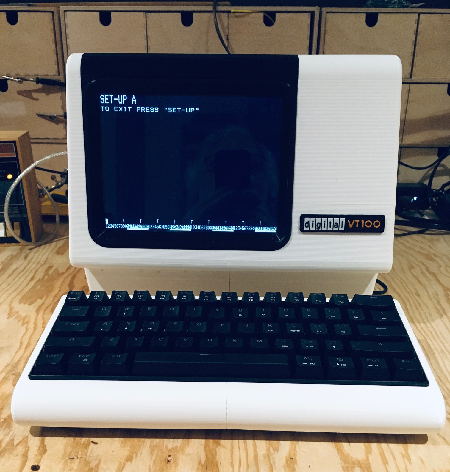
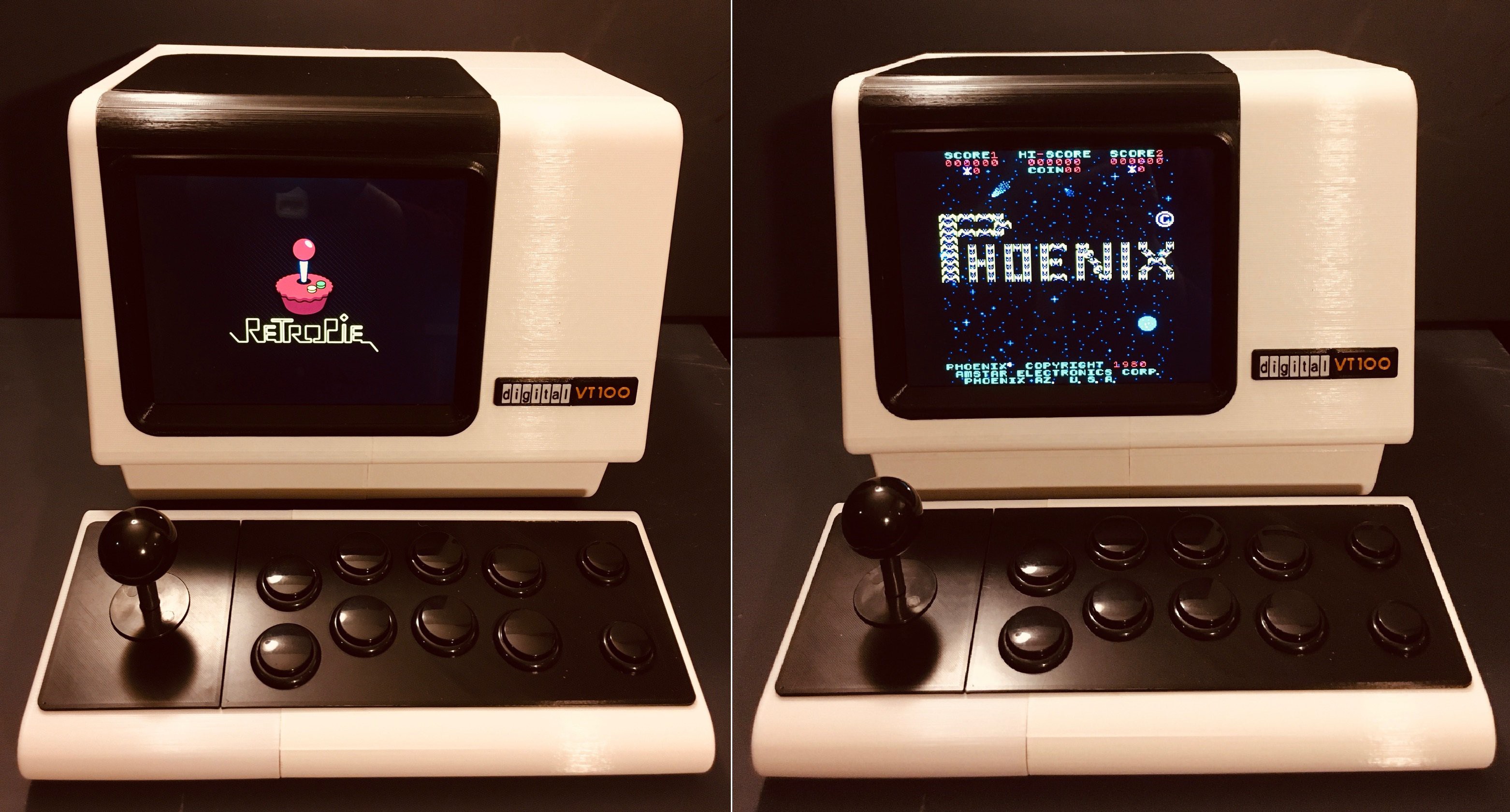
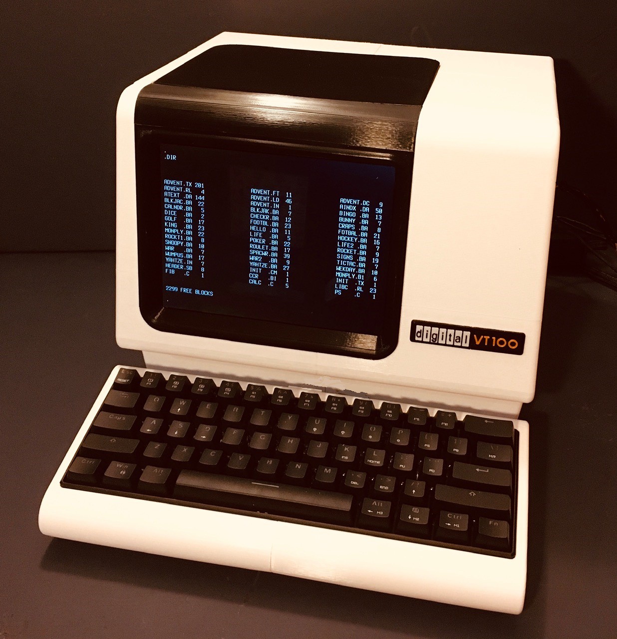
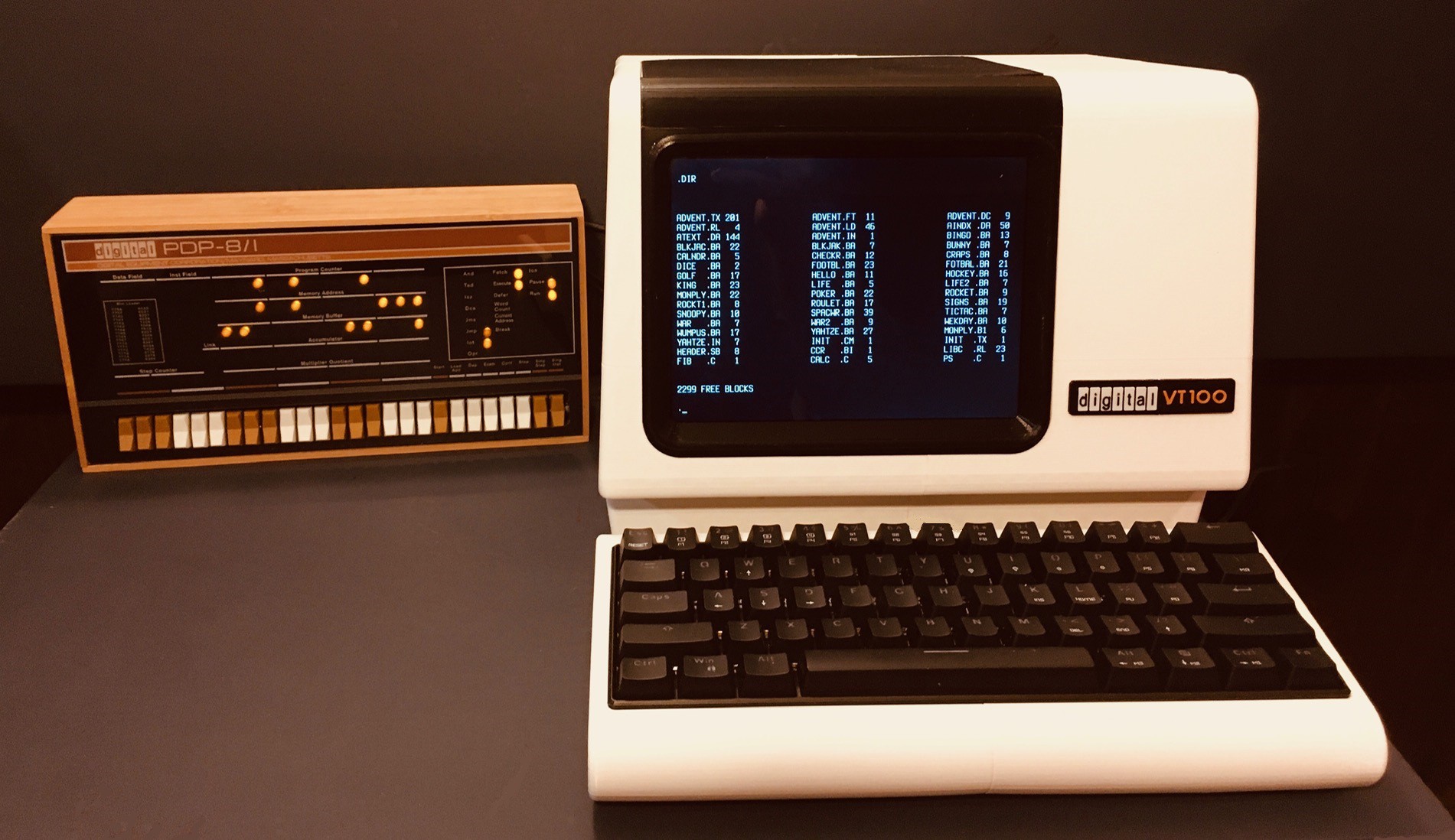
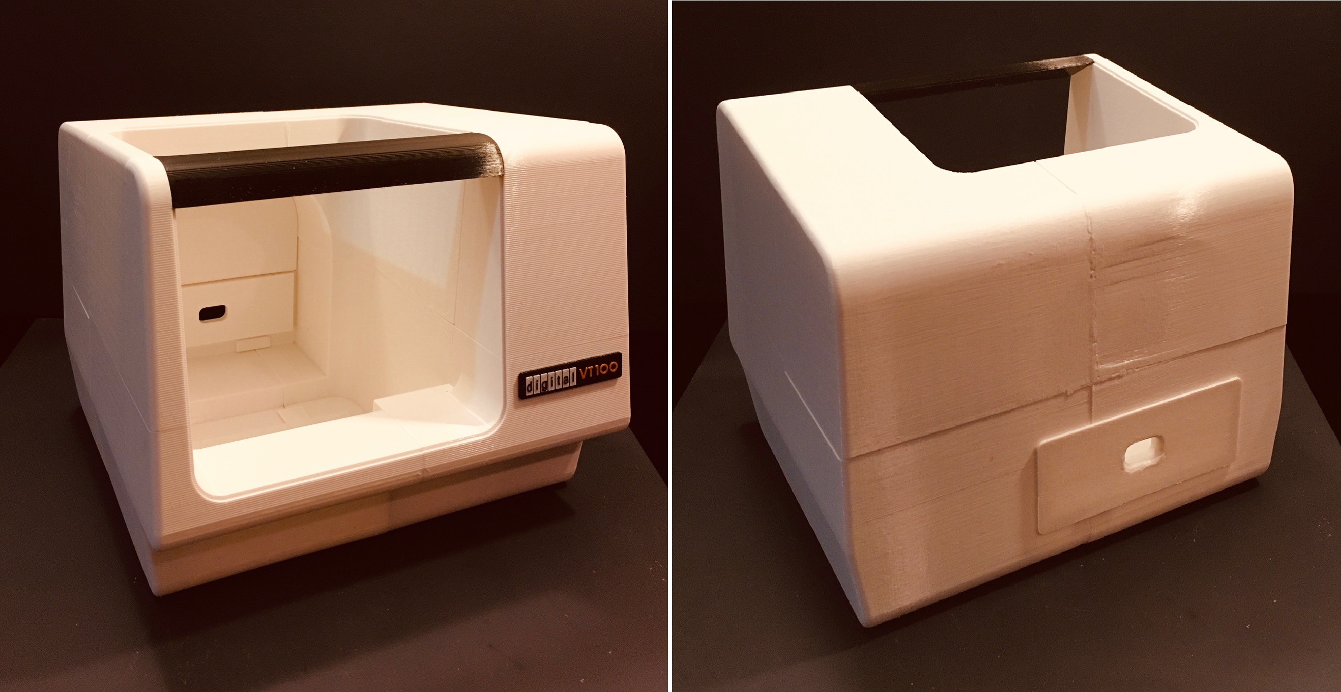
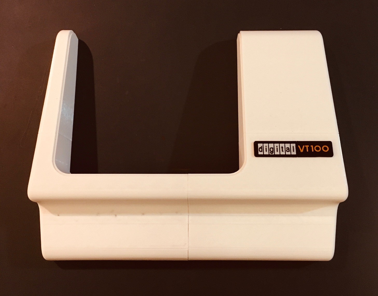
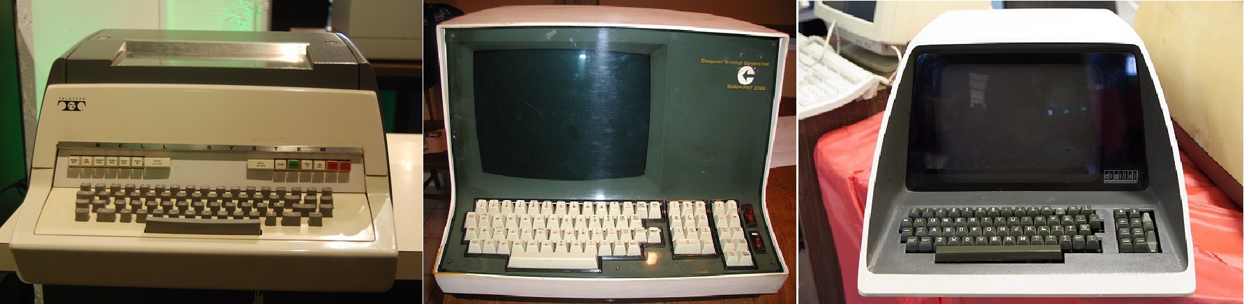
Since the DEC VT100 was the gold standard for serial terminals in the early years, that's what I will base my design on, and since it will be a driver for a 2:3 scale PDP-8I I'll scale my design accordingly.
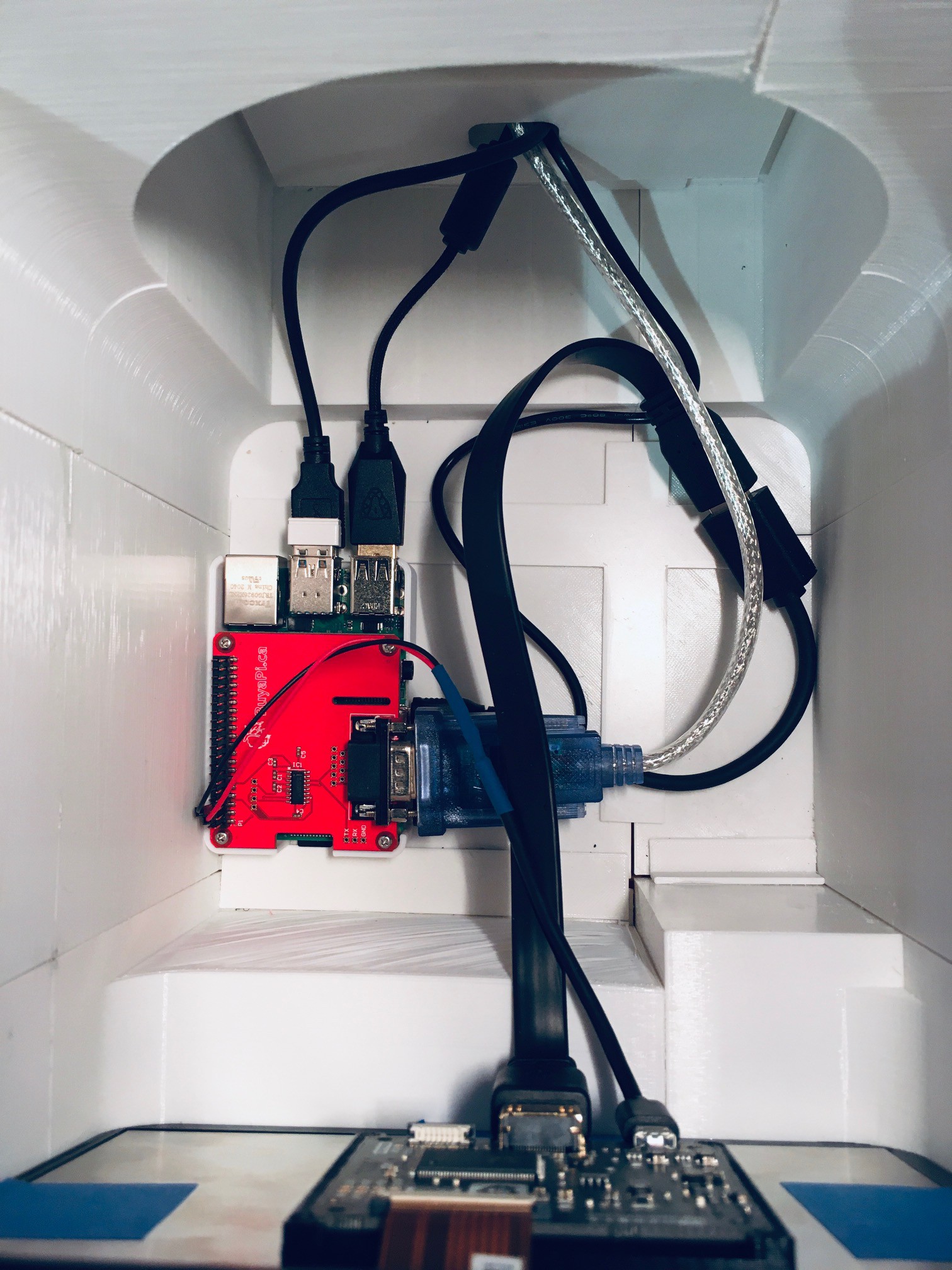
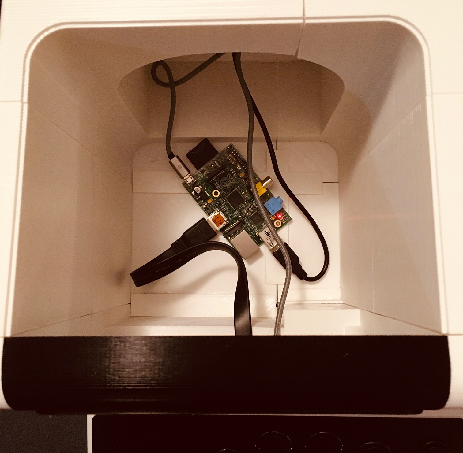
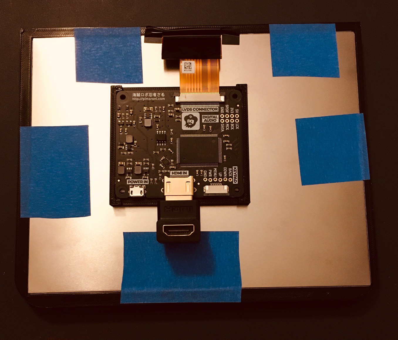
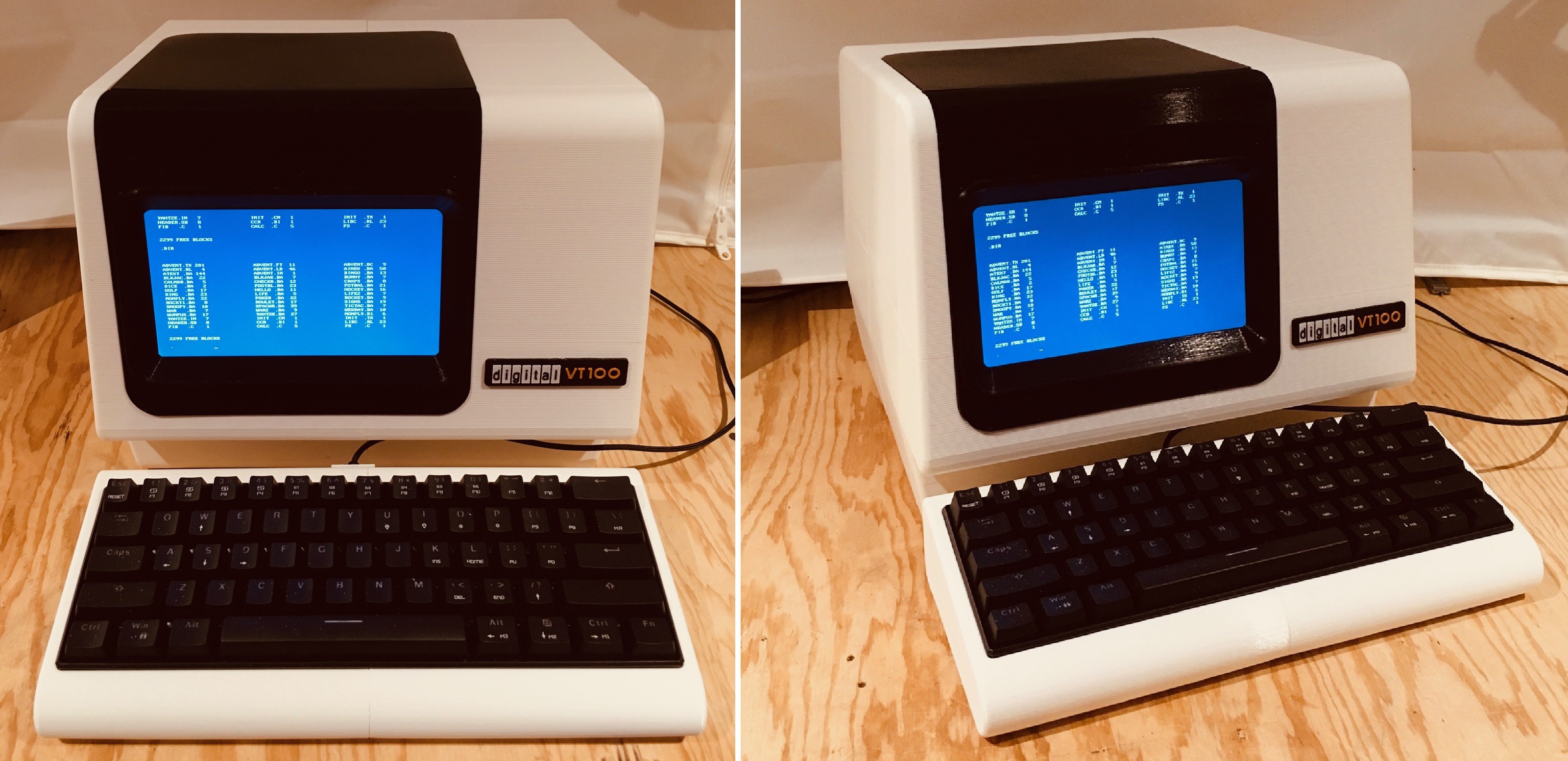
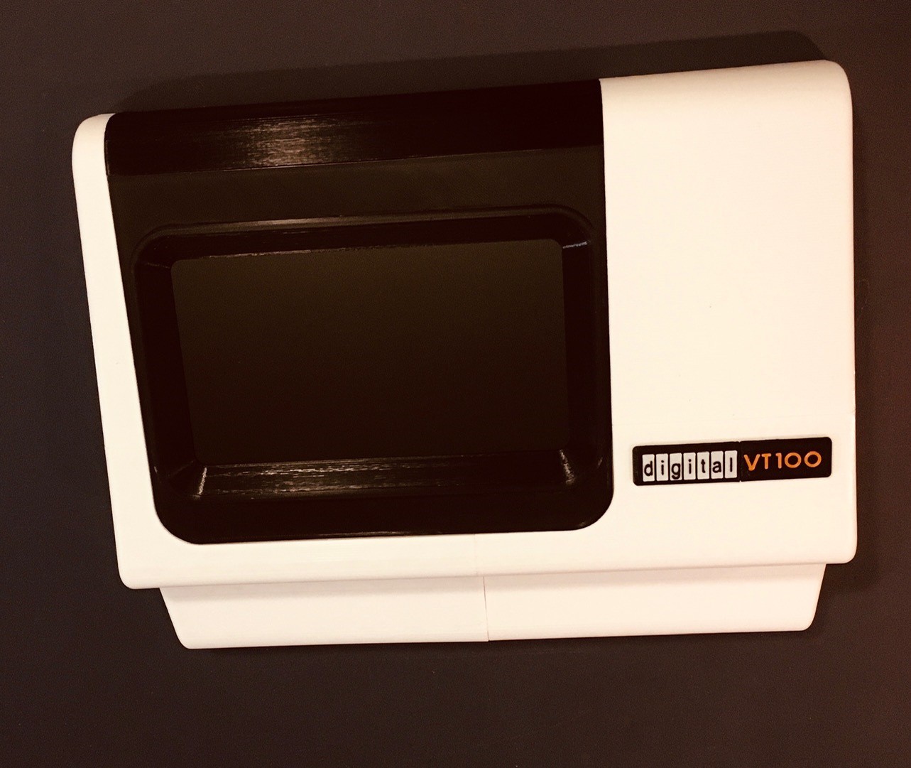
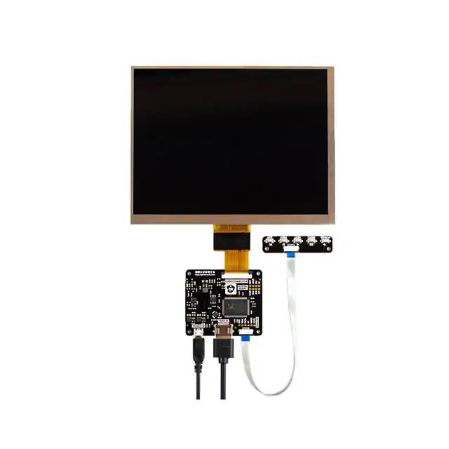
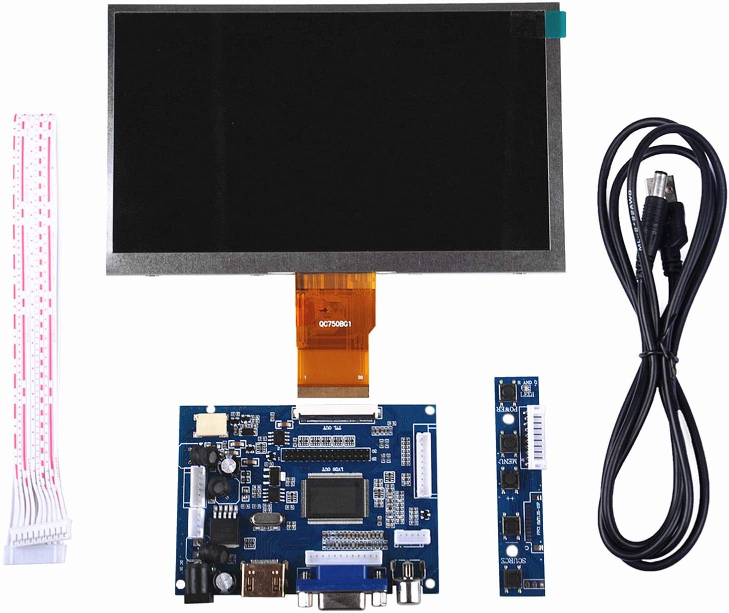
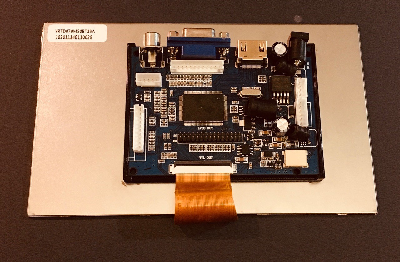
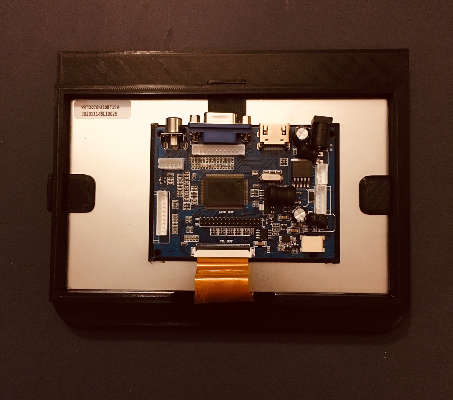
I will not be making a true replica VT100. The plan in fact is not even to make a real serial terminal. I want to make something that is clearly a VT100 derivative as close as possible in look, but sourced with modern components. So for instance it will have an LCD screen disguised as a CRT, and the 2:3 scale precludes having a full sized keyboard with number pad like the original. The display will be hooked directly via HDMI to the Raspberry Pi running the PDP software, and the keyboard will be USB connected to the Pi as well.
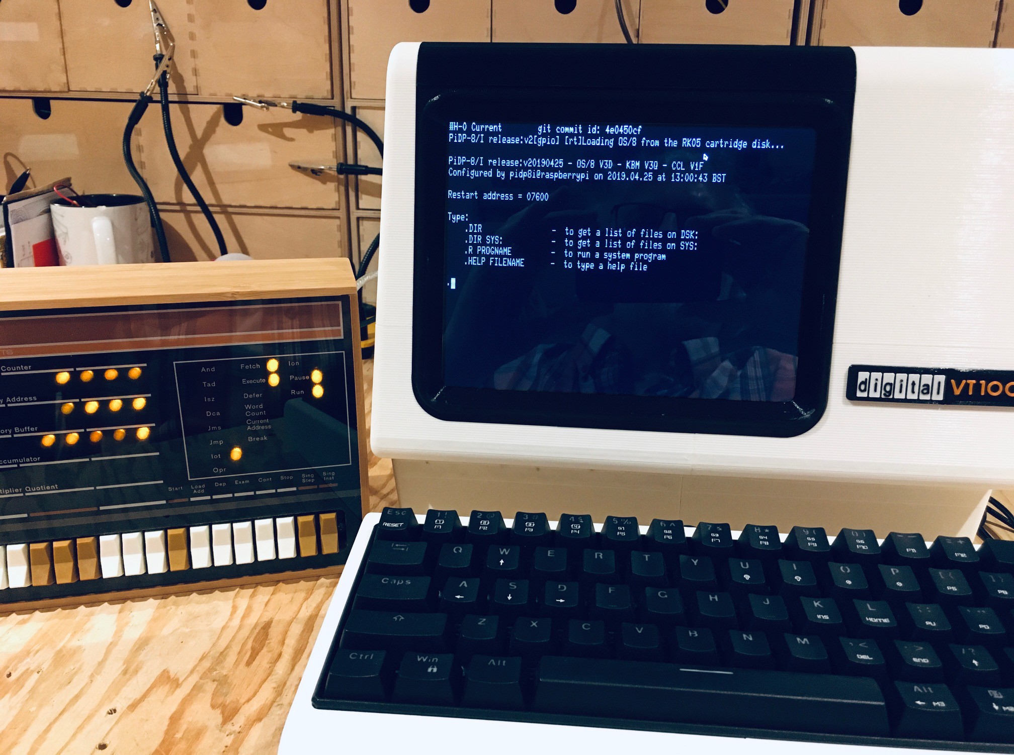
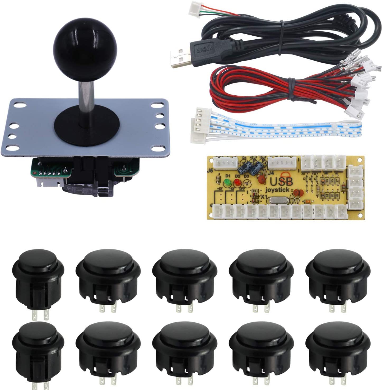
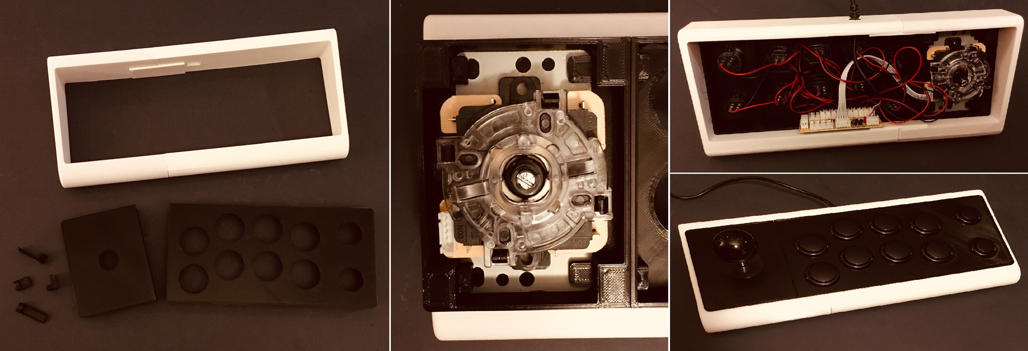
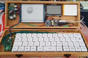
May 27, 2021: The previous two paragraphs describe the project as originally conceived. As the project progressed I realized that there was so much more I could do with this reproduction. Near the end of this writeup you will see that I created a Mini Arcade version with joystick and buttons in lieu of a keyboard. Since the RetroPie software for the arcade was running on a Raspberry Pi anyway, and we did have a keyboard as well it's wasn't a big leap to see this VT100 reproduction as a small stand alone desktop machine.
My very last sentence in this writeup was "The one thing that I didn't do was create an actual RS-232 terminal. I don't have the bandwidth or a use case for this now, but based on projects like PiTERM, it looks like it would be pretty easy create a third variation that did just this." Well as part of this update I plan to correct this shortcoming. See the new sections at the bottom for details.
May 29, 2021: With the RS-232 hardware sorted I wanted to take one more step and achieve as authentic a VT-100 experience as I could. Thanks the the efforts of Lars Brinkhoff I was able to do just that. More details at the bottom.
I managed to find a VT101 Video Terminal User Guide online, and basically, for someone that often does reproductions of artifacts that they can't actually afford to buy, struck gold.
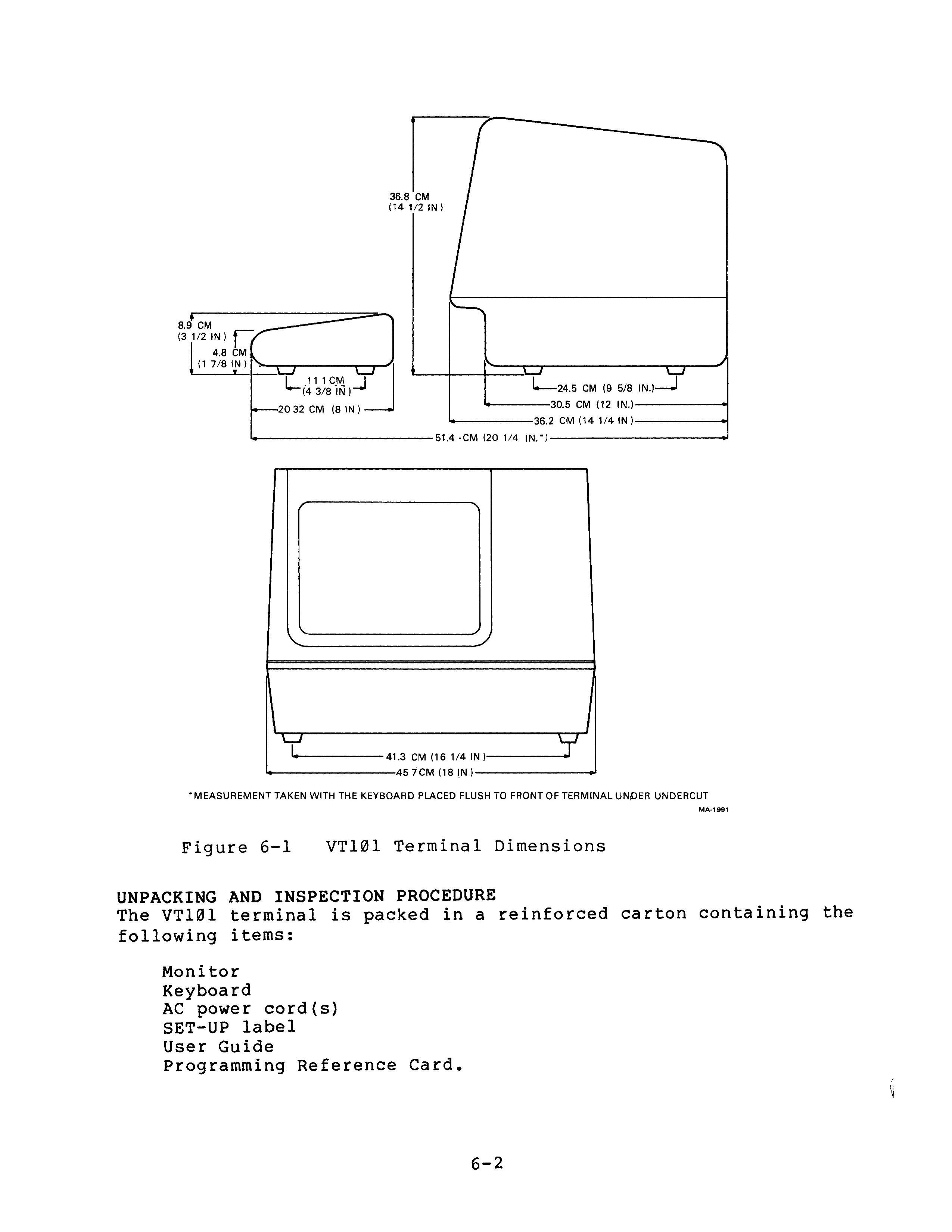
Figure 6-1 is all I need to create a suitably scaled VT100 3D model.
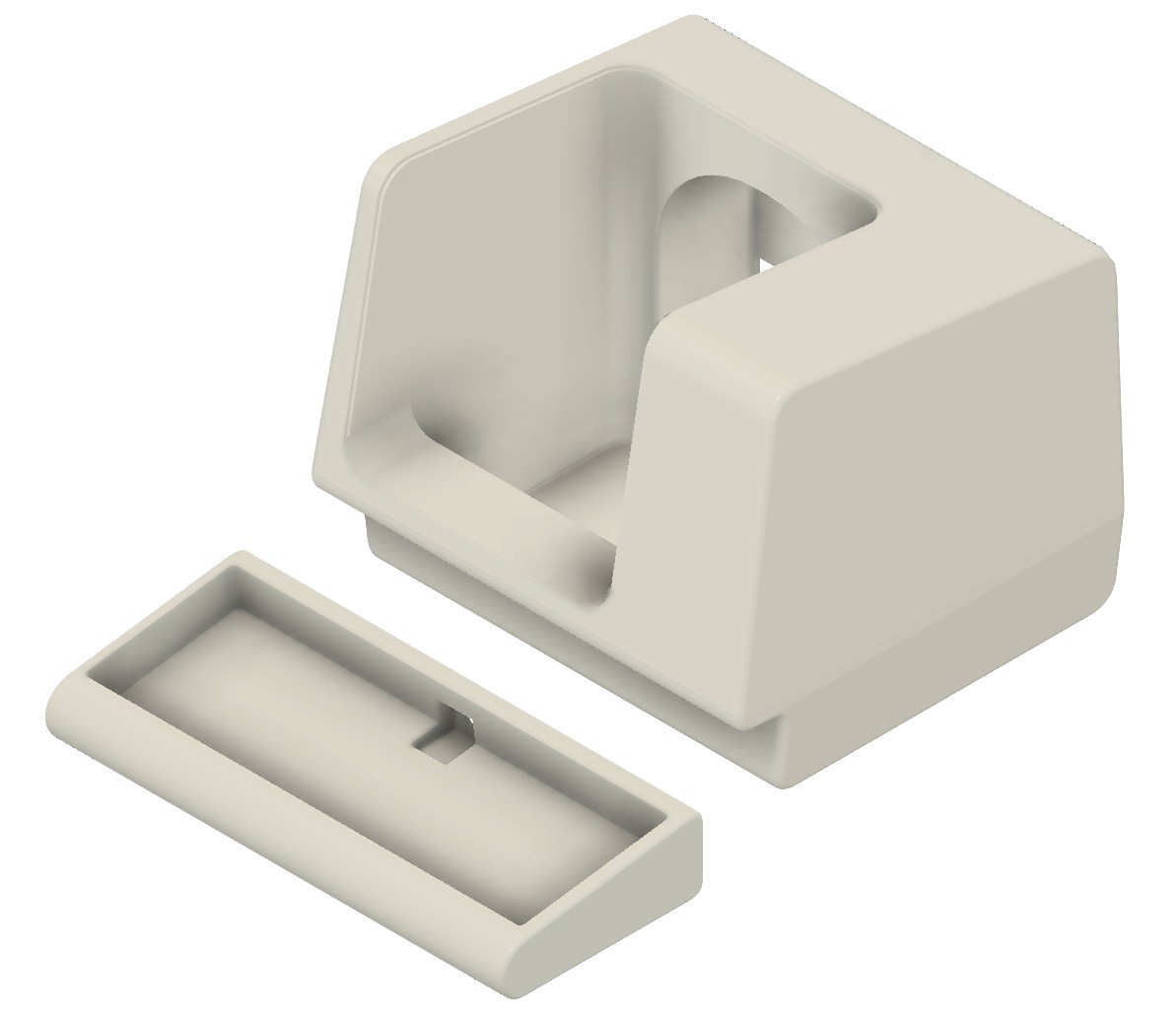
So just a couple of hundred hours of 3D printing (seriously the keyboard alone is 30+ hours or so), and shoehorn in a keyboard and display and I'll be done.
At a point where I had already printed about half of the terminal pieces I found this photo.
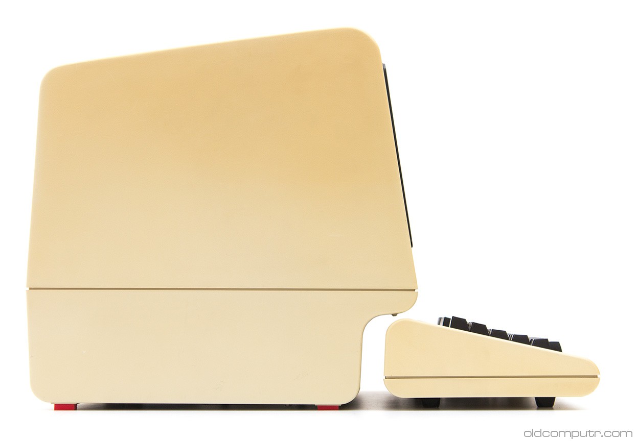
Notice the back of the terminal has a bend in it like the sides do, and unlike the drawing in Figure 6-1. Too late to adjust my design. Sigh, a small miss here.
Who Knew Keyboards Were Such a Big Thing?
Probably most of the people reading Hackaday knew, but not me. I think because I'm not a touch typist (long story), one keyboard is pretty much the same as another to me. That is certainly not the case for the large and vocal group of keyboard enthusiasts out there.
When I scaled down the keyboard frame and measured, I found that at most I had an area of 295 x 110 mm to fit the actual keyboard. Yikes! So I began my quest for the perfect keyboard for this project.
I have a couple of smallish Bluetooth keyboards around and thought something along those lines would do the trick, but after a pretty extensive search could find nothing suitable.
For a while I thought about creating a custom keyboard based on the SICK-68 design I found in these very pages. But that felt too much like a complete project inside of my project. So no.
After that it didn't take long before I stumbled upon the wild world of mechanical "gaming" keyboards. 40%, 45%, 60%, linear vs tactile, Cherry MX, ortholinear vs staggered, so much to learn. The good news for me was the many of these designs had a form factor small enough to fit into my VT100 keyboard frame.
Case in point, the Planck EZ is only 234 x 82...
Read more »


 Nick Scratch
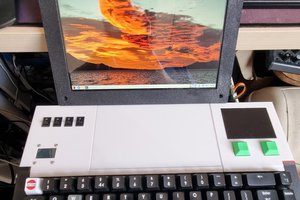
 Steve Anderson
 0x17
0x17
 dave
dave
Hi. Not having a 3d printer, would it be possible to just upload the zip file for this project to a 3d printing service? (e.g. https://www.sculpteo.com/en/ ), I'm completely new to anything regarding 3d printing and while I'd love to get a printer and learn how, I just don't have the time or bandwidth right now. If using an online service would work, is the current project zip file the one with the update for the PIM372 screen and Motospeed keyboard? Do the ".stl" files contain color information? Or does that need to be specified separately? If just building for the terminal, would I just delete all of the .stl files with "gamepad" in the title?
Thanks.