 Vipin M
To be honest, I find the snakes a bit creepy. But their gait is very graceful and attractive.
Robots modeled after snakes have been around for quite some time. The earliest literature I could find on Robot snakes was a 1976 paper by Hirose and Umetami in which they discuss the biological principle of lateral inhibition used for controlling the Active Chord Mechanism (ACM) with tactile sensors. Since then, there has been a lot of research in characterizing the movement of the snakes and lot of DIY attempts to imitate that.
There are mainly 4 kind of gaits that have been identified in snakes - serpentine, sidewinding, rectilinear and concertina. Serpentine is known to be very common and is what I have attempted in this project. My main goal with the project was to make the snake robot more accessible (low cost) by using inexpensive off-the-shelf parts.
Guts
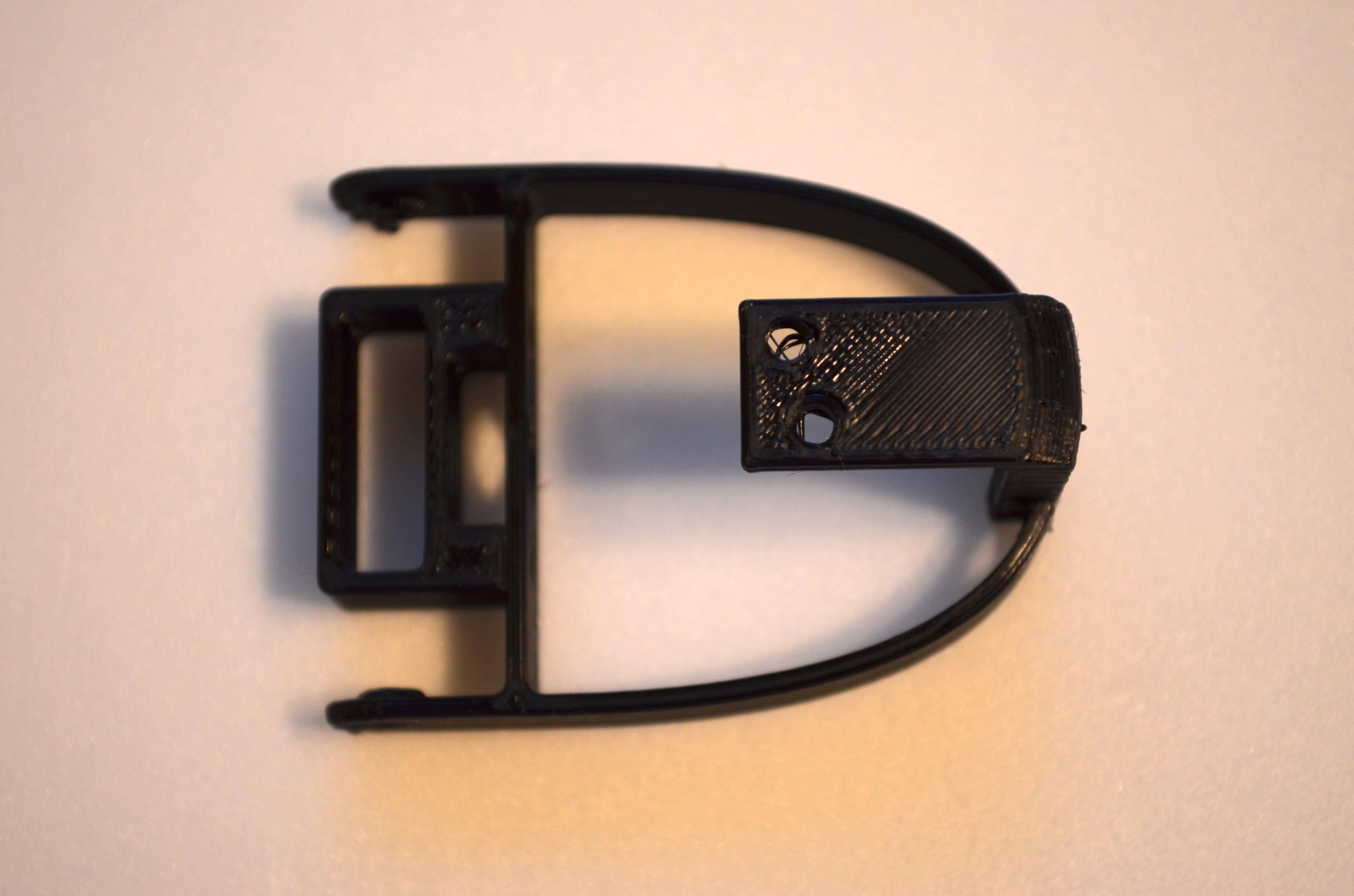
I started by reviewing the skeletal structure of a snake. Using that as a starting point, I designed one of the ribs in Fusion 360. After a couple of iterations, I settled on the following design as it seemed to work well in both form and function.
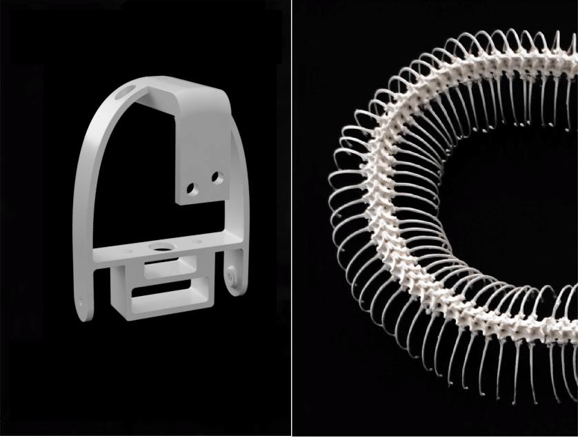
- It was modular and so could be easily extended to achieve the desired length of the snake.
- The outer contour was smooth to allow for installation of an artificial skin.
- It was light in weight which would allow its actuation to be easily handled by a micro servo.
Locomotion
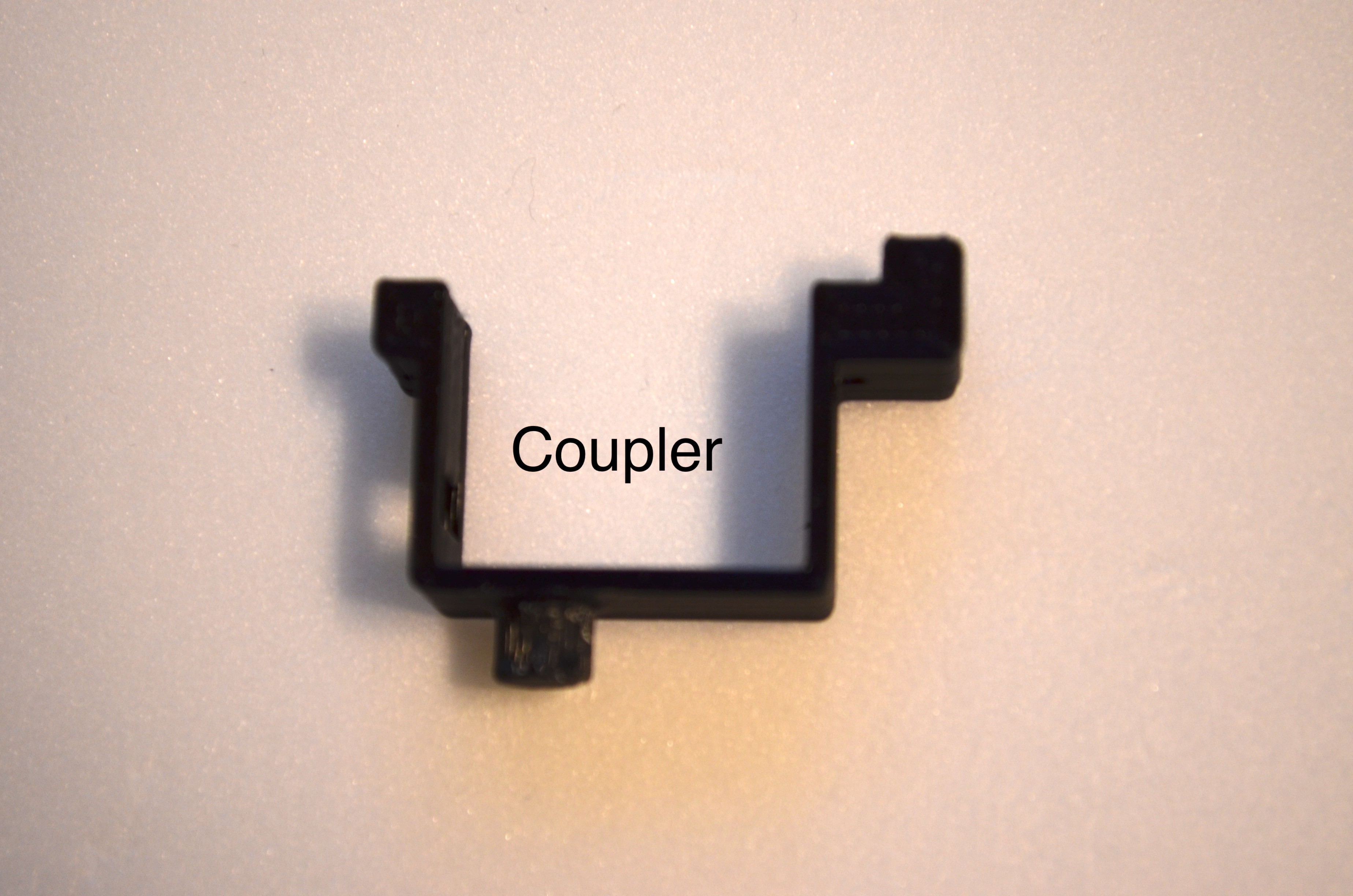
For snake locomotion, I decided to stick with the use of passive wheels as the mechanism is simple and effective. The wheels were 3D printed and the axle was simply an M2 screw turning inside an M3 sleeve to minimize the cost.
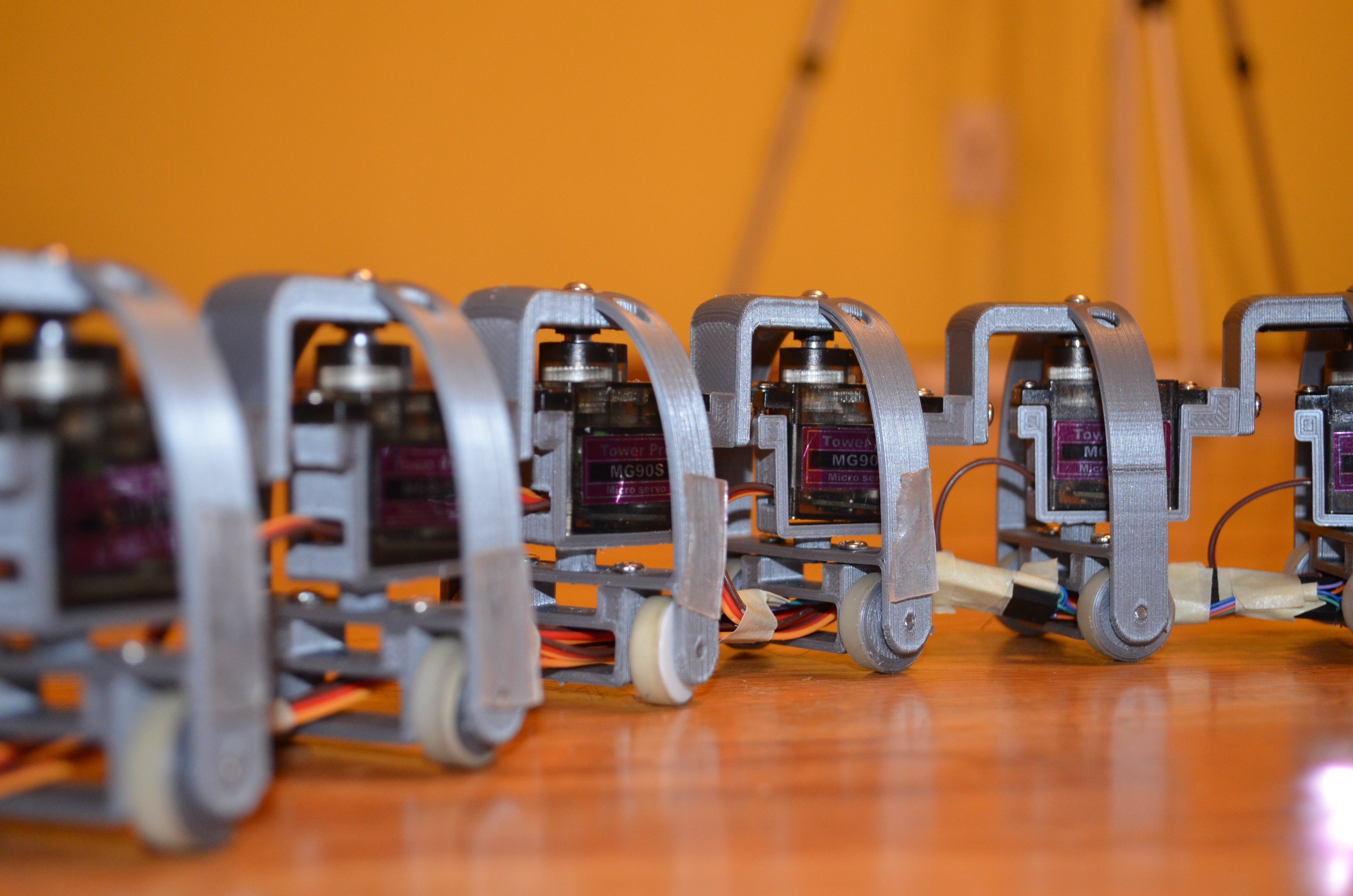
A 16 servo controller I had came in quite handy. It meant that I could attach 16 MG90S motors and make the size of the snake a bit more life like. From head to its tail, the slitherbot measures more than 1 meter (~ 1134mm).
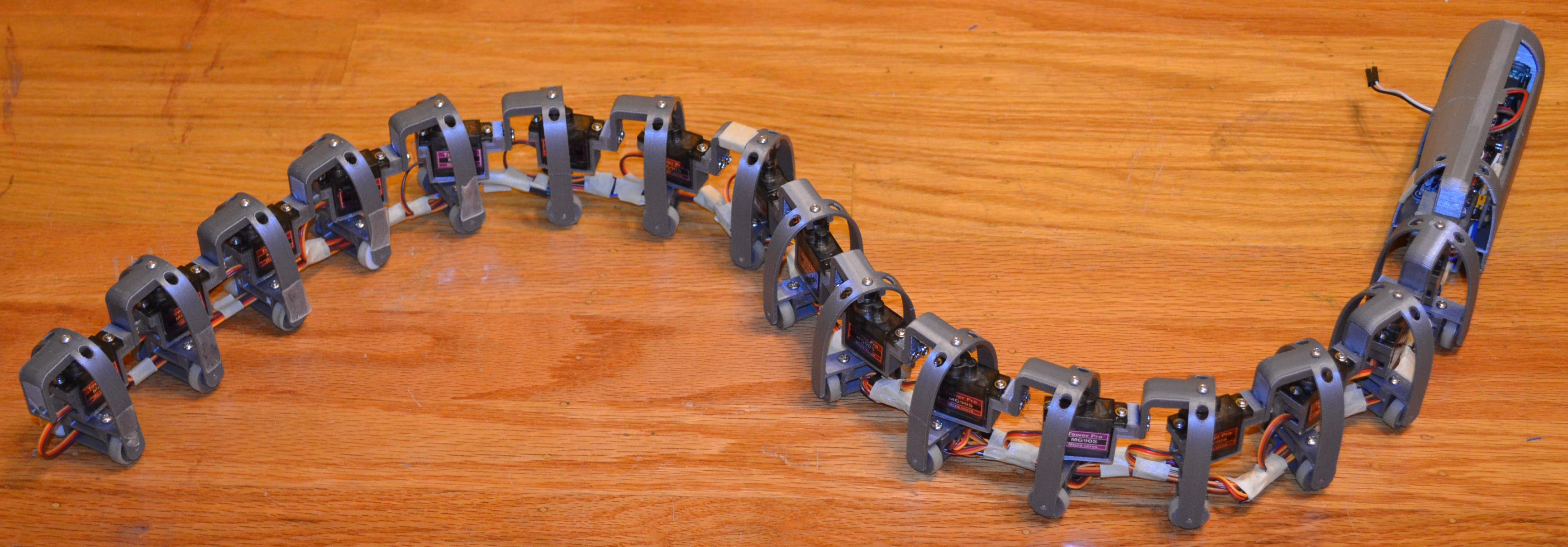
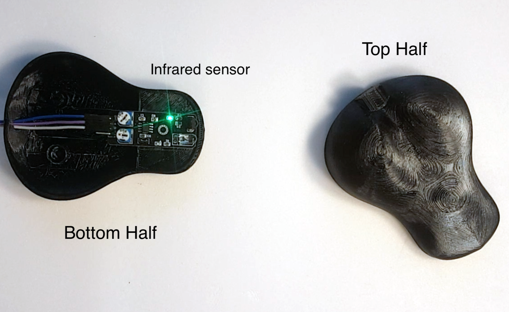
With all the links connected as shown, I was able to get the desired motion by simply passing a cosine wave through the robot's body. One can also varied the wave's amplitude to give a more natural feel to the slither. I also added support for obstacle detection using an infrared sensor.
Skin
To make it a bit more realistic, I decided to give a skin to the robot. I started by modelling the skin in CAD but after several iterations and trying out different materials, I was not getting anywhere. The problem was that after putting any kind of covering, the micro servo's were restricted enough to not produce the serpentine motion I was looking for. I have listed some of my unsuccessful attempts later in the blog to document them.
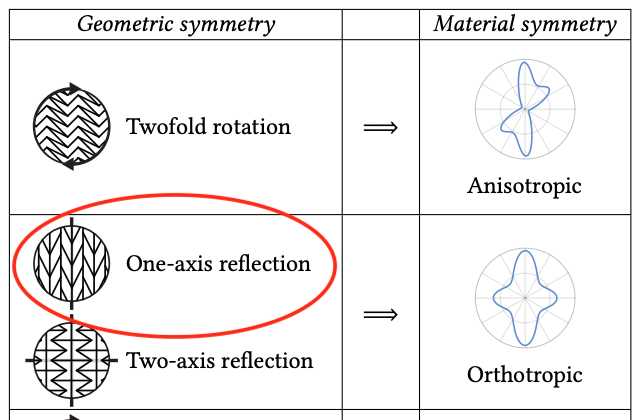
Finally, I stumbled upon the following research, Mechanical Characterization of Structured Sheet Materials by Disney Research. The paper proposes a comprehensive approach to characterizing the mechanical properties of structured sheet materials. Two-dimensional linear materials can be classified into four symmetry groups:
- Anisotropic
- Orthotropic
- Tetragonal
- Isotropic
The various material symmetries lead to characteristic Young’s modulus profiles and can be related to the structural symmetries of the underlying tiling.
For the slitherbot, the Young's module profile of the orthotropic group looked fairly promising. The research team has put together a nice interface at http://structuredsheets.com/. Based on my requirements and the suggested options, I decided to go with the following pattern for the skin design.
I then modeled the design in Fusion 360 and printed it using TPU. The result was really amazing. It worked exactly as the research outlines.
Design Choices
- To improve traction of the wheels, I put a small rubber band around each of the wheels.
- Routing the cables from the servo motors need some planning since we are not using serial servos ($$). To reduce the number of wires coming to the electronics housing, I ran a voltage and ground rail through the entire length of the snake so that the...

 Martin Vincent Bloedorn
 Aaed Musa
 adambeedle
I used Tinkercad to make the base under the servo bracket about 3-4 mm thicker so the bracket now rotates in the bottom part. I also made the cable carrier part of the rib so I don't need screws to connect. The wheels shown on this site are thicker than the ones provided at Thingiverse. There is not much info on how to connect the ribs together. The holes on both pieces are about 3mm, and thanks to filament shrinkage are a little smaller so they might self-thread. I would use brass screw inserts instead to ensure the ribs stay connected.