Close
0%
0%

K-line to CAN Converter

bridge vehicle communication busses with the [mini::base + mini::bike]

Similar projects worth following
We’ve been working on this for a few weeks, now. It’s basically an extension board for the mini::base with an IC for Keyword Protocol 2000, which is part of the OBD-II standard and was quite widely used before the broad adoption of CAN. (Don’t quote us on that. It’s complicated.) The hardware of mini::bike is actually very simple, but it’s extremely helpful when working with this protocol. The rendering above (which includes a Molex connector that’s common in vehicle applications) should give you some idea of what it might look like in a final product.

Why is it called mini::bike, you ask? While you can still find Keyword Protocol 2000 in use by early OBD connectors in cars from the late 90s—and I can personally attest to the fact that it was used in Mercedes-Benz C-class automobiles up through 2005, give or take—you are most likely to find it in motorcycles, snowmobiles, and jet skis these days.

The Use Case

Let’s say you have a Suzuki GSX-R 1000, and you want to eavesdrop on the communication between the engine control unit (ECU) and the dashboard. First, pull over and get off the bike. Never hack a two-wheeled vehicle while riding it! (The same rule applies to jet skis, by the way. For obvious reasons.) To accomplish this, your setup might look a lot like the one in the image below, except that there’d probably be a vehicle involved. A vehicle, and less weird white furniture…

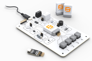
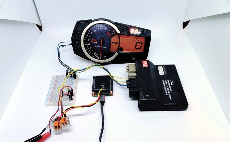
Lab setup for the mini::bike showcase

The lab setup above doesn’t show much. There’s no running engine and no peripherals doing anything. But it does show a mini::stack consisting of a mini::base and a mini::bike, wired with open lines through a breadboard to both the ECU and the dashboard.

The Example

The first step—the one we are documenting here and the one for which we are providing sample code in our GitHub repository—is to dump out the communication from the bus to the serial console:

And there you go. You just dumped status information from the bus of your Suzuki to your serial console. From here, you could use the mini::stack to convert the information to a CAN signal and send it out to another device, such as a data logger.

Be Advised

Our boards do not have an automotive certification. While they are built to last, and the engineering is solid, the components are not "automotive grade." What we have presented above is a laboratory example and is not fit for real-world application. Nor should you try to use this hardware on the open road (even if your vehicle has four wheels). Always be aware that vehicles are dangerous, and make sure you don’t harm yourself or others when tinkering with them.

Suzuki_GSXR_1000_K9.pdf

Suzuki GSX-R 1000 manual

Adobe Portable Document Format - 28.47 MB - 04/06/2021 at 17:09

Preview
Download

suzuki-gsxr-test.ino

test code for Suzuki GSX-R 1000

ino - 5.99 kB - 04/06/2021 at 14:50

Download

MINI-BIKE-A001-1-0-0-BOM.xls

Bill of Materials

ms-excel - 10.51 kB - 04/06/2021 at 14:50

Download

ms-excel - 1.24 kB - 04/06/2021 at 14:50

Download

x-zip-compressed - 42.61 kB - 04/06/2021 at 14:50

Download

View all 7 files

  • 1
    Step 1 - connect the hardware

    First, we have to wire up the mini::bike to the motorcycle. Therefore we need to find the diagnosis port in order to get access to the K-Line connection. In case of a Suzuki GSX-R 1000 it is located under the seat:

    Position of Diagnosis plug

    Connect the mini::bike to the diagnosis plug. For the Suzuki, the connection should be like the following:

    mini::bike wiring diagram

    The DM in the drawing stands for "Dealer-Mode". This replaces the little switch it usually needs to set your motorcycle into "Dealer-Mode". With the mini::bike, an onboard optocoupler does the job.

  • 2
    Step 2 - connect to your PC

    After sucessfully connecting the mini::bike to the motorcycle, It's time to connect the mini::bike to your PC.
    You'll need a USB Type C to USB Type A cable to get the job done.

    There is a detailed description on how to get started with the board::mini series on GitHub

  • 3
    Step 3 - flash the software

    When everything is set up correctly, the last step is to flash the example code we provide on GitHub.

    Download or clone the code and open it in the ArduinoIDE. Click the "Upload" button in the upper left. After successfully flashing the code to the board, you should see the data of your motorbike in the serial console.

View all 3 instructions

Enjoy this project?

Share

Discussions

Justin D wrote 10/06/2023 at 12:07 point

The Github link doesn't work.  Curious if the creator of this page could re-share the code?

  Are you sure? yes | no

Justin S. wrote 10/03/2023 at 14:30 point

Super interesting. The K-Line is used on my 2008 m109r. Hoping to use this info to develop my own DIY project to read live values from the ECU/Diagnostic port. Thanks for the project! 

  Are you sure? yes | no

Similar Projects

Does this project spark your interest?

Become a member to follow this project and never miss any updates