0%
0%
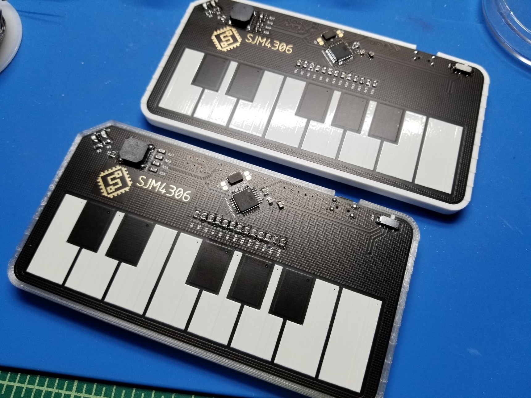
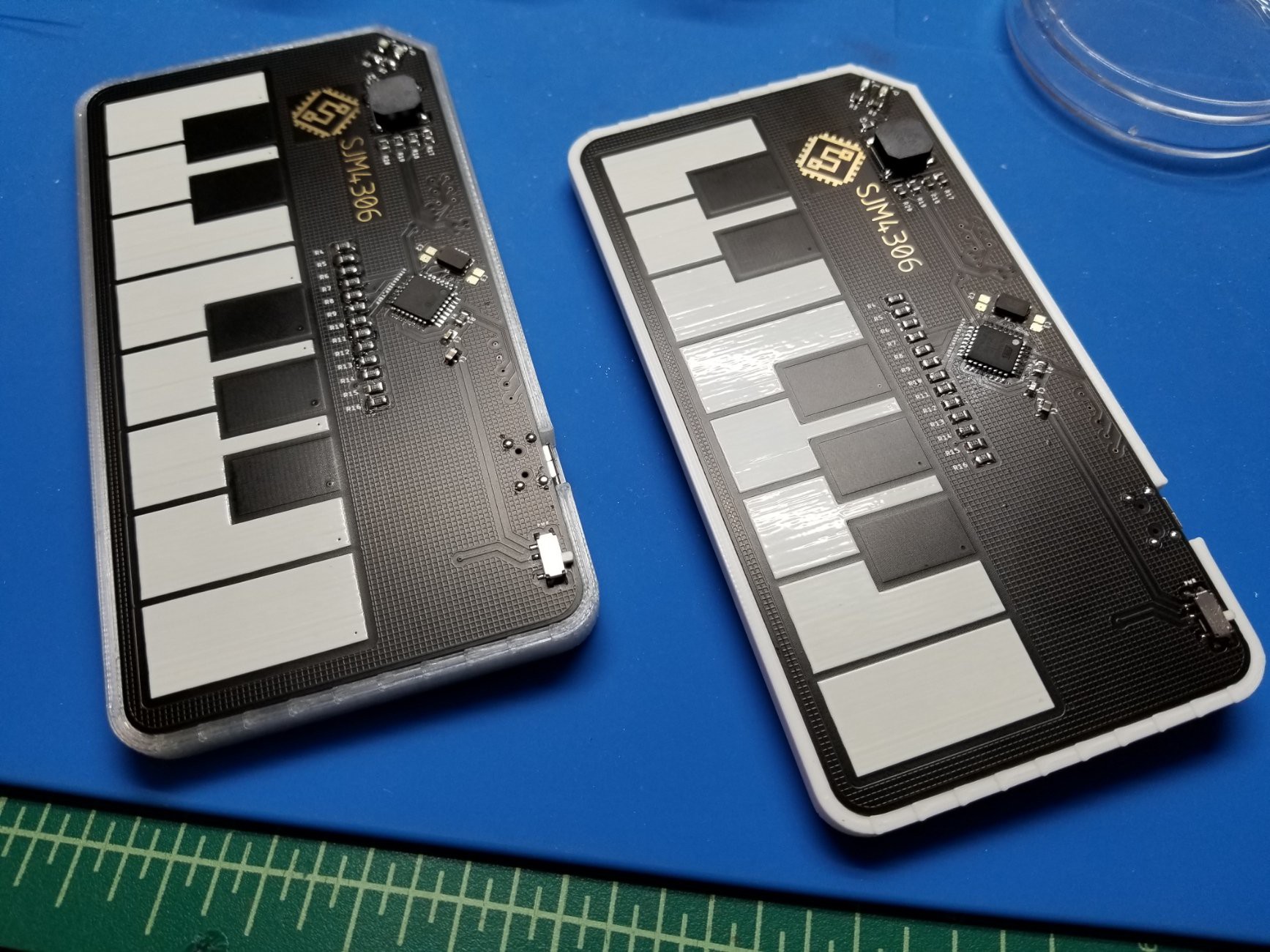
Polyphonic Touch PCB Piano
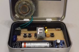
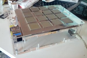
Pretty much exactly what the title describes, can play 4 channels of polyphonic squarewaves at once triggered by 13 capacitive touch keys
 sjm4306
Become a Hackaday.io member
Already have an account? Log in.
Just one more thing
To make the experience fit your profile, pick a username and tell us what interests you.
Pick an awesome username
hackaday.io/
Your profile's URL: hackaday.io/username. Max 25 alphanumeric characters.
Pick a few interests
Projects that share your interests
People that share your interests

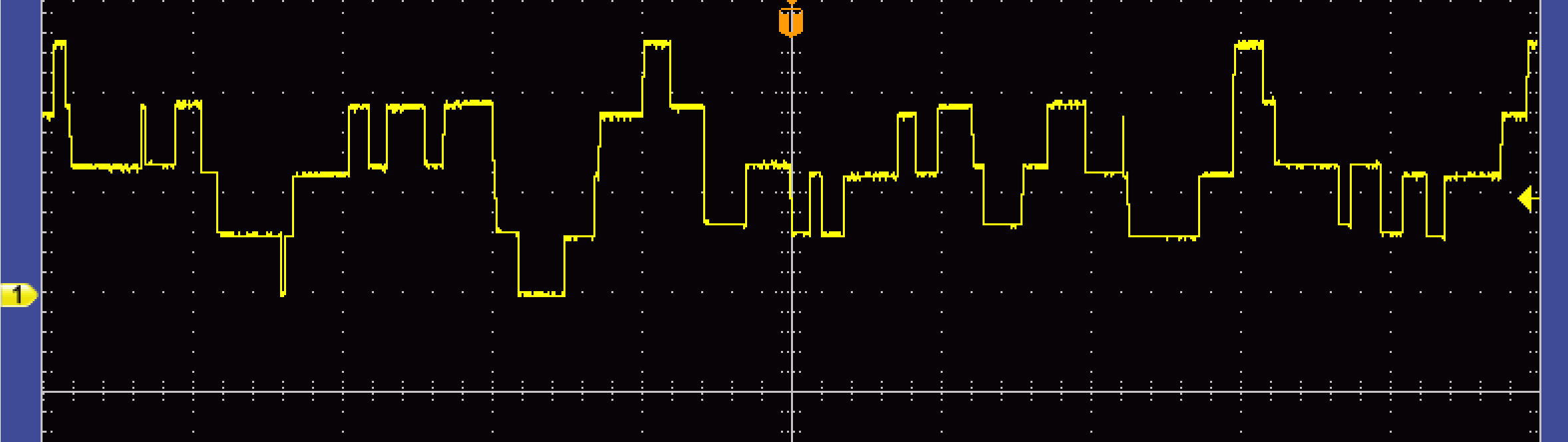 Pretty much like a very coarse digital to analog converter, which makes sense since summing though resistors is similar to using a resistor ladder except all bits have the same weight in this case. Here you can see that there are effectively 5 discrete states (including the zero level), with the highest being when all 4 channels are high and the lowest when all 4 channels are low. It's pretty interesting that this garbled mess actually sounds like 4 distinct notes played at the same time.
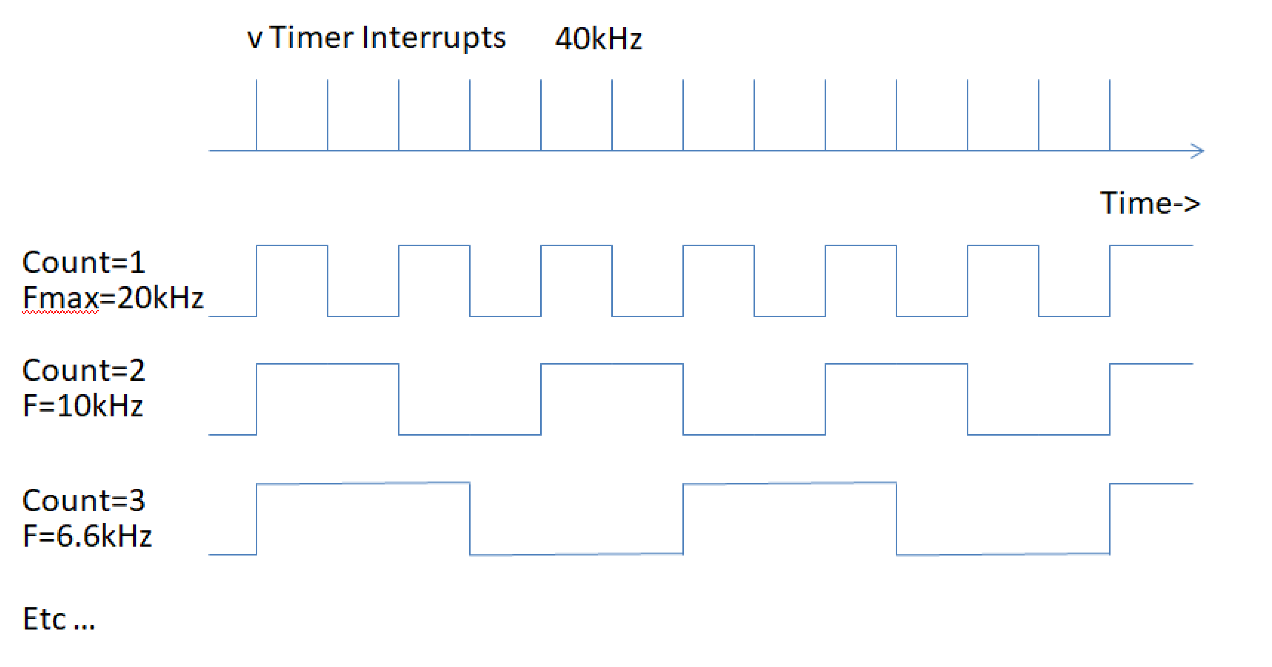 I wanted at least 4 channels to be playable simultaneously (based more on the gpio I had available after deciding I wanted one full octave of keys). To achieve this, each channel has a counter, compare value, and an enable/disable bit. Each time the interrupt is executed it checks if each channel's count is equal to the compare value for that channel. If not then it increments it and does nothing to the output pins for that channel. If so then it clears the count and if the enable/disable bit is set it toggles the output pin. To ensure this all works properly the time spent in the interrupt must be fairly short. Executing at 40kHz I measured the interrupt execution time to be around 8us out of the available 25us period (meaning it consumes ~32% of the cpu processing time). If I wanted...
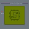

 Michele Perla
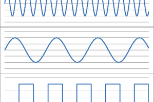
 gannon
 Matias N.
Have you considered using different resistors in the adder, basically constructing a 4 bit DAC on the hardware side, and doing the multi channel adding on the software side?
Like PORTC = (PORTC & 0xf0) + f0on + f1on +f2on +...
If my theory is correct this should add a lot of channels, or enable more advanced waveforms, like sawtooth or triangle.