 Matias N.
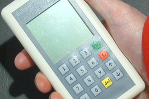
In general one can find the typical simple and featureless bicycle computer which only count speed/distance and (supposedly) calculate sport-related information (such as burnt calories and fat). There are also more advanced bicycle computers but they typically rely on a smartphone for obtaining more information (such as GPS location or pull weather forecast), which means more battery on both the device itself and on the smartphone. Furthermore, they seem to be aimed towards the competitive cyclist.
In contrast, for the case of bicycle touring there's much more useful information one could have, such as elevation (current and change), compass orientation, temperature, etc. At the same time, there's no good reason to attempt to replace all the functionality of a smartphone.
BicycleCompanion is a modern bicycle computer aimed towards bicycle tourists, featuring various sensors while still consuming very low power, without requiring a smartphone connection (in fact, it does not provide any wireless connectivity at all).
Currently bicycle companion is in development but the following specifications are more or less defined:
- Based on STM32L476 low-power microcontroller which allows for different types of sleep modes
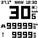
- Uses Sharp Memory LCD display (similar to e-ink, much faster refresh rate). Currently I'm testing a 1.3'' 128x128 display, but I may reconsider going for a 2.7'' in the future
- Four hardware tact buttons for good mechanical feedback (touchscreens are difficult to use while riding)
- LiPo battery (possibly a few hundred mAh). I'm aiming for a battery life of at least one month of typical use (ride around 8-10hs hours a day, low use when off the bike)
- USB recharging via waterproof connector. Also used for firmware updates and import/export settings
- Battery level indication (ideally, with an estimate of remaining run-time)
- RTC time-keeping
- EEPROM for storing settings even if battery completely dies
- 3D printed case with some level of waterproofing and accesories (magnet mount, etc)
- Piezo buzzer for feedback beeps and wake-up alarm or signaling other events
- Sensors:
- Reed switch: this is what most low-cost bicycle computers use. Hall sensors may be better but they draw considerable power. As a plus, it can be made compatible with existing mounts.
- Accelerometer + magnetometer: mainly to give compass orientation. The accelerometer can also be used to detect bike motion and activate the device from sleep or could be even used as a motion-based alarm
- Temperature + pressure sensor. Pressure can be used both as weather information (storm warning) as well as for sea-level altitude information (for measuring elevation changes during rides).
BicycleCompanion was originally designed as a teensy shield (which was never built) and then as a custom board based on the low-cost STM32F103 microcontroller (check early logs of this project) and using an OLED for display. This board was built but it was too power hungry. Moreover, it lacked any other interesting sensors to justify its use. Therefore, BicycleCompanion design is the result of this evolution.
 For future boards (and for an eventual BicycleCompanion rev2) I would consider including a good SWD connector instead of the SOIC, which could be left unpopulated in the final build. However, for something that is intended to be easily hackable I think the best approach is to embed a ST-Link 2.1/BlackMagicProbe IC to the board, which would offer real debugging and hardware serial communication over USB. This can be achieved by adding an STM32F103 chip and flash either image. This would increase the BOM by approx 5/6usd, and occupy quite a bit of space on the board, but it may be worth it.
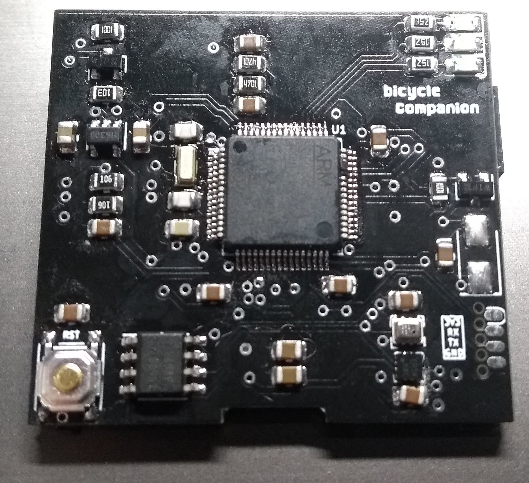
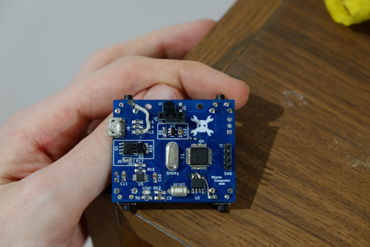
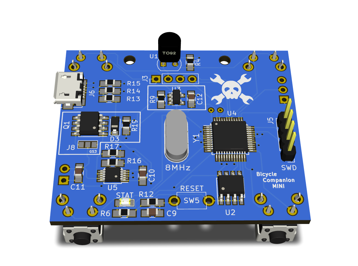
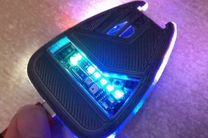
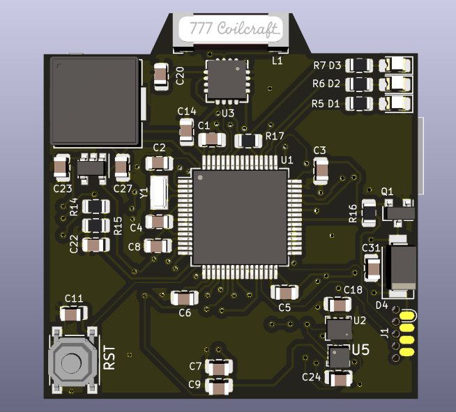 This is the front view where you can see the IC, reset switch, piezzo buzzer (that big square at the top-left corner, yeah it is huge), three LEDs (top-right corner), the lightning sensor below its antenna (middle-top). The IMU is U5, that tiny little thing (will I be able to solder it by hand?) below the barometer + thermometer IC (U2). At the right you can see I used the SOICbyte programming header which I thing is quite cool.


 Xasin
Xasin
 Boz
Boz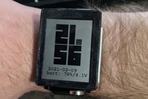
 Jeff Cooper
Congratulations on the Bootstraping Prize @Matias N. !