0%
0%
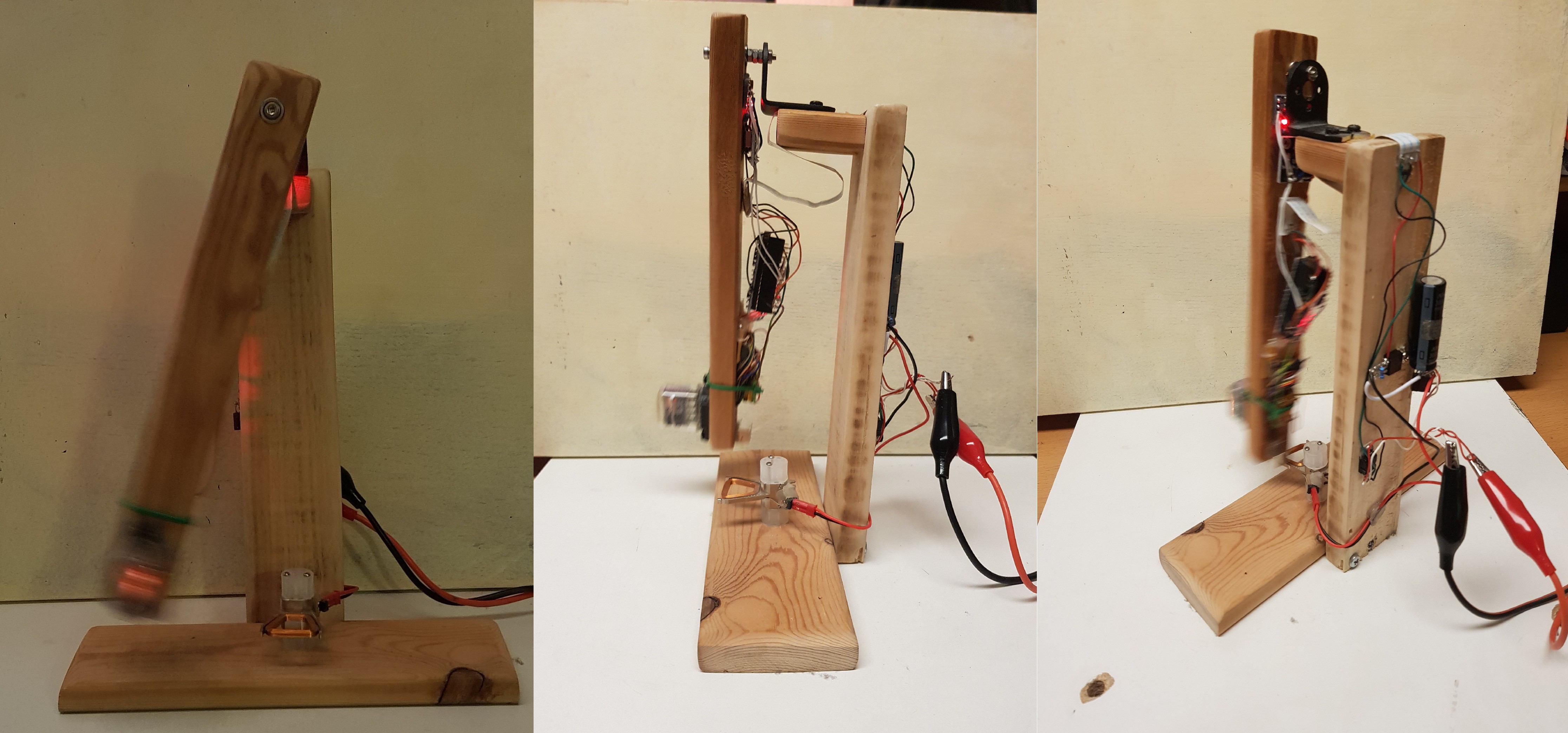
Nixie Pendulum Clock - Concept
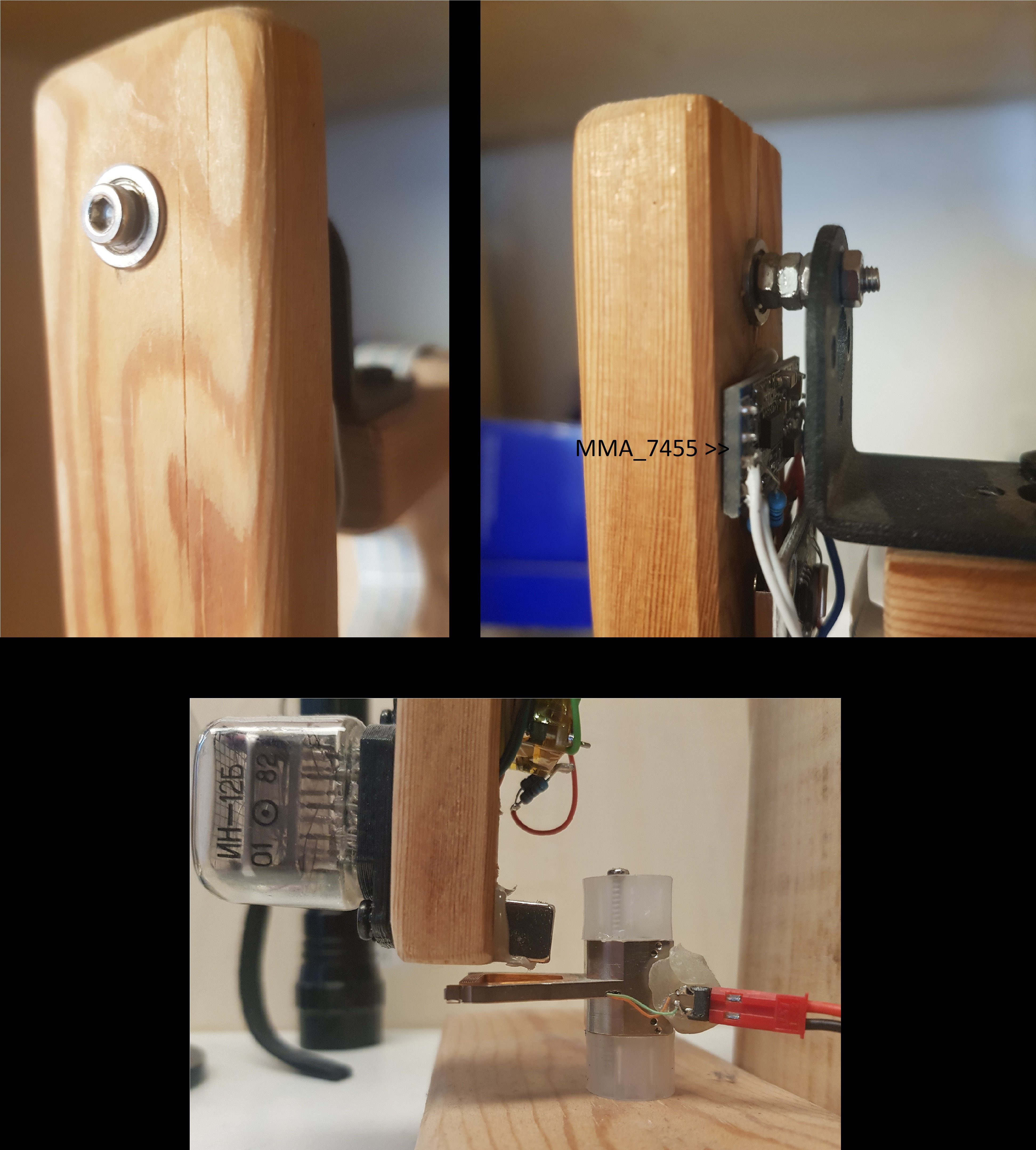
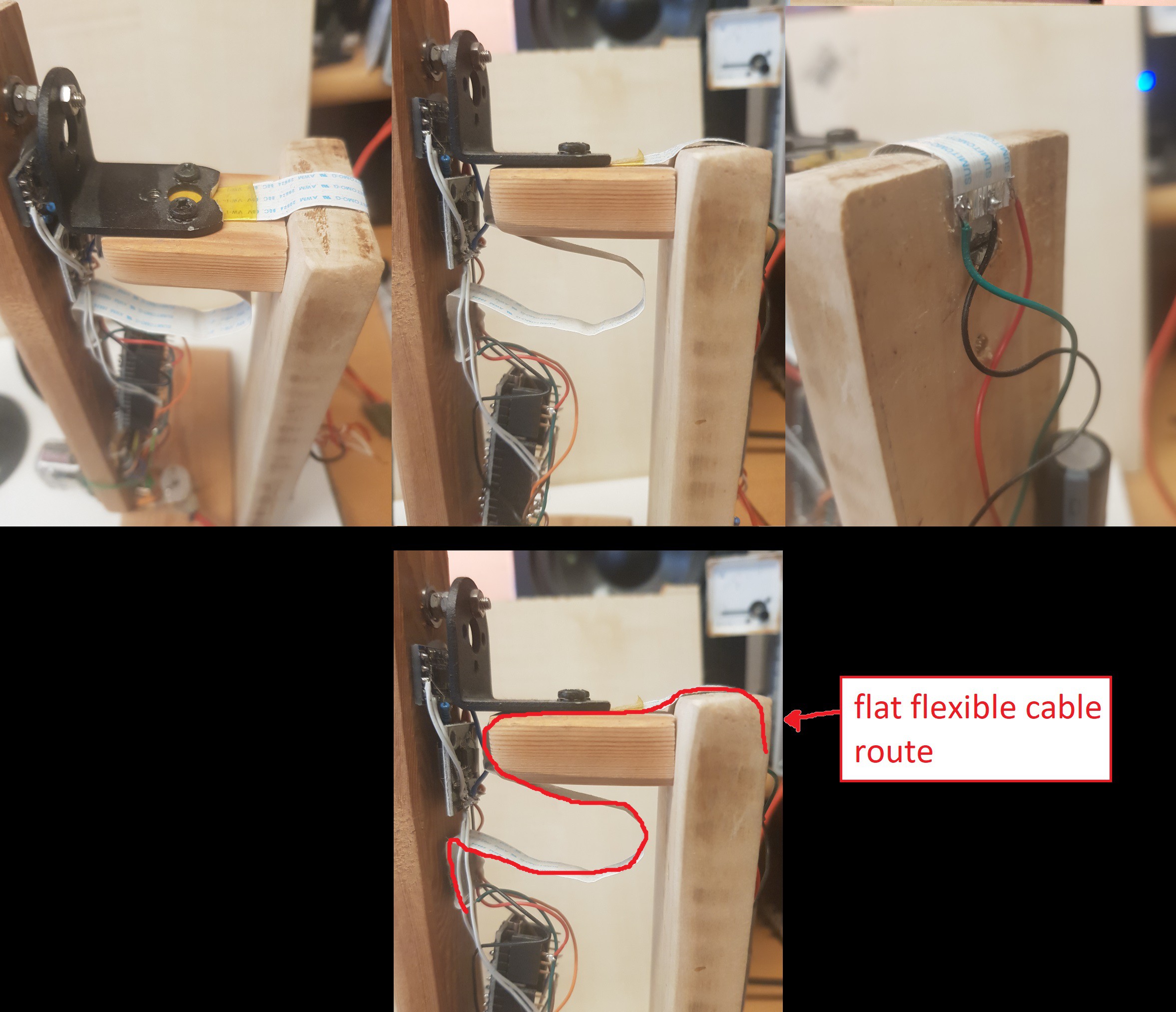
A pendulum clock with a NixieTube (IN-12b) that plots the time in the air it passes.
 j
jBecome a Hackaday.io member
Already have an account? Log in.
Just one more thing
To make the experience fit your profile, pick a username and tell us what interests you.
Pick an awesome username
hackaday.io/
Your profile's URL: hackaday.io/username. Max 25 alphanumeric characters.
Pick a few interests
Projects that share your interests
People that share your interests


 Xasin
Xasin
 PixJuan
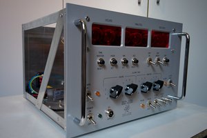
 Marten Electric
 andriy.malyshenko
I do really love this project (being a clock fanatics !)
Thats's a pity that the PoV effect is so limited...