 Anton Poluektov
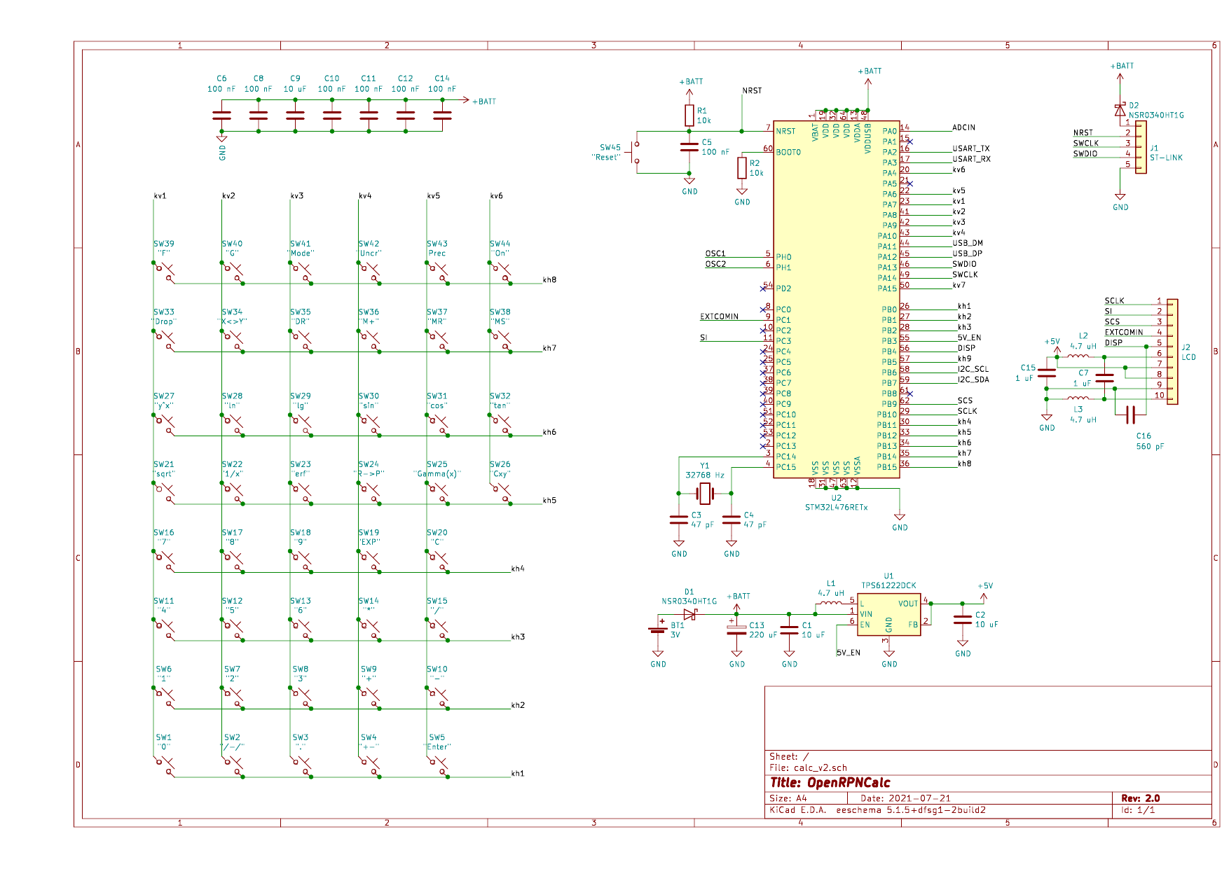
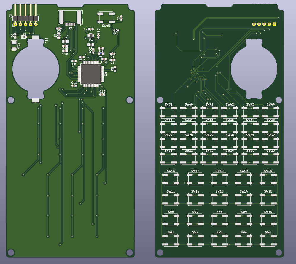
The calculator is based on low-power 32-bit ARM microcontroller STM32L476 running at 8 MHz, which is more than sufficient for the purpose. The display is the famous Sharp memory LCD module LS027B7DH01 (400x240 pixel monochrome). Keyboard uses light-touch tactile switches Panasonic EVQQ2B01W (50g actuation force). All electronics runs off the 3V lithium battery (CR2032) that should be sufficient to provide power for several years of operation.
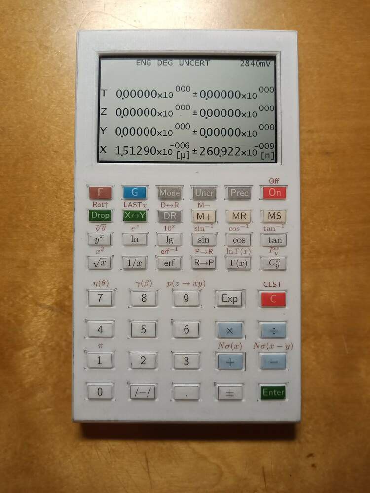
The case and keyboard is made of four 3D printed parts (top and bottom parts of the case, keypad and switch spacer). The two parts of the case are held together by simple snap fit joints, no screws are needed. For the moment, while the software is under development, the buttons are labeled with a simple laserjet-printable sticker paper.
Currently, the calculator features:

- Reverse Polish notation with 4-element stack.
- Double-precision arithmetics.
- "Standard" scientific calculator functions (trigonometric, logarithms, exponentiation, square root and power).
- Error function (erf) and its inverse (erfinv).
- Fixed, scientific (SCI) and engineering (ENG) display modes (including SI prefixes in ENG mode), variable 3-10 digits precision.
- Calculations with uncertainties using error-propagation formulas (UNCERT mode). Something that I've never seen in any of the hardware calculators, and very rarely is present in the software ones.
- Low power consumption (~10 uA in standby mode with LCD display on, 2-3 uA with LCD off).

 Nguyen Vincent
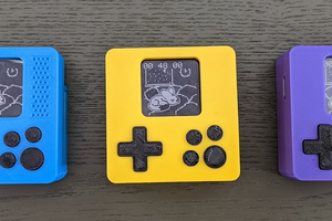
 NanoCodeBug

 Stephen Harrison
Been thinking about doing one of these myself. Nice to see someone else gets the importance of indefinite battery life. If you put a color TFT on a calculator you may as well just use an app on your phone!
Button labelling is the key (sorry) issue to solve. Two ideas:
1. Put a column of four or maybe even five keys adjacent to the left and/or right edge of the display. Then you can have dynamic 'soft labels' on the screen to support vastly more functions with fewer keys. An overall landscape design might then be attractive with all the keys to the left and right of the display.
2. I've never seen it done, but it should be possible to 3-D print double-shot keys using a two-filament extruder. Failing this, would it be possible to print the top part of your existing key design in clear plastic and stick printed labels on the back of this so the clear plastic protects the label?