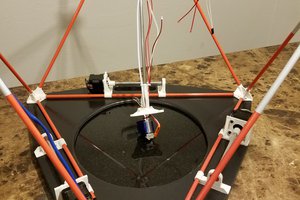
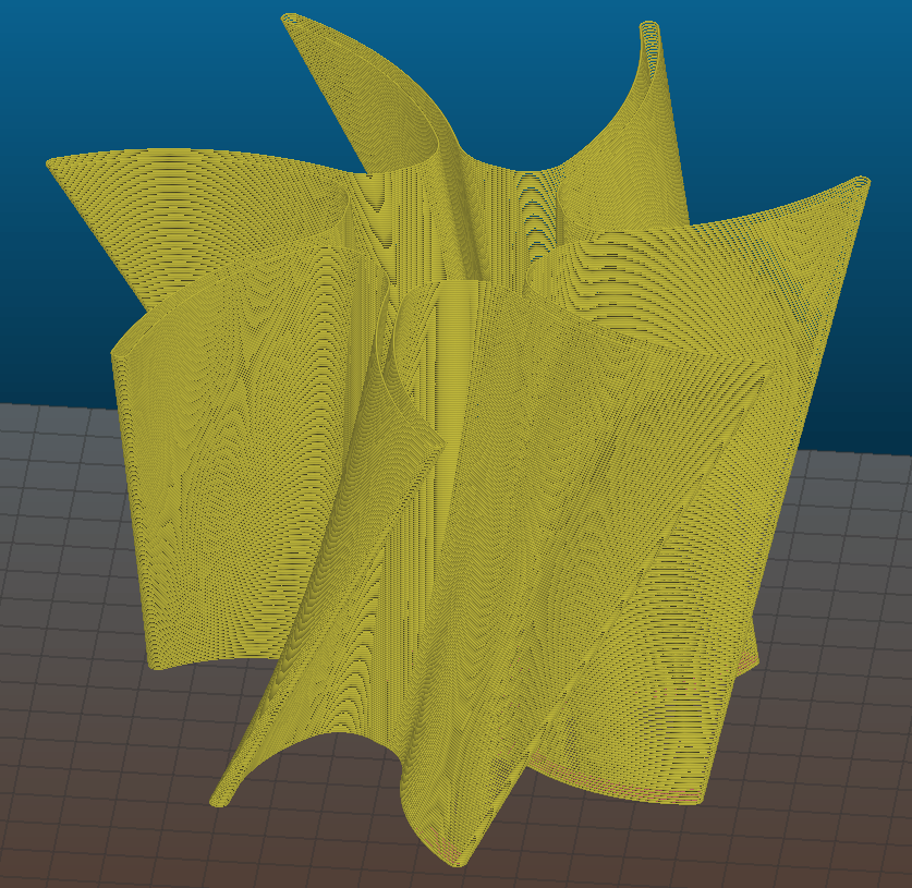
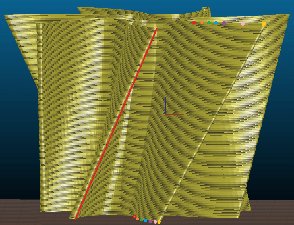
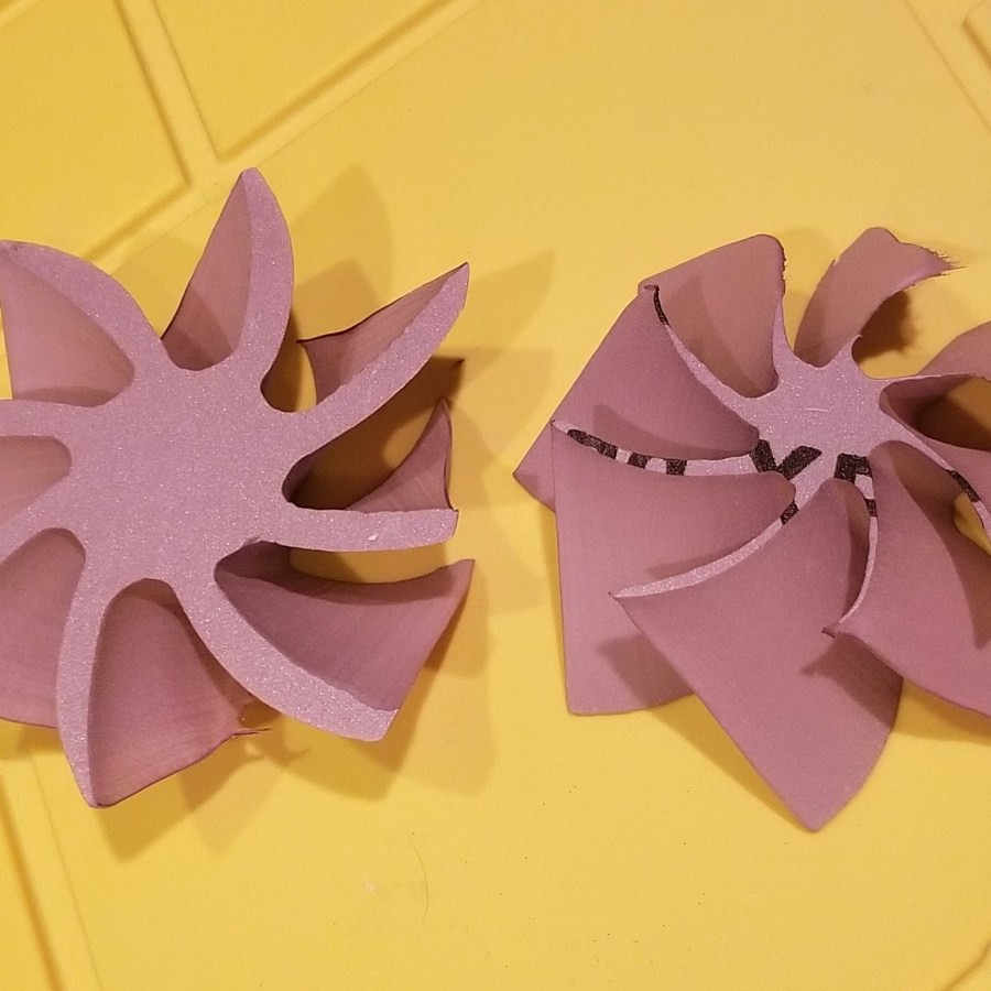
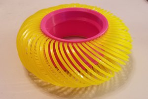
I saw a couple of these drawing robots at the Portland Maker Faire. There are a few commercial ones available: Makelangelo, Polargraph, QuickDraw Bot. The basic version consists of two stepper motors mounted to the corners of board. Pulleys hang down from the motors and meet in the middle to hold a pen. The motors move the pen making a drawing. For years, I have wanted to build some very large 3D objects. I had seen this video about making a car body (the Bailey Blade) using foam: https://youtu.be/xdsFLRmEtpI, and I realized I could cut the cross sections of a 3D model similar to the Bailey Blade video using two of these drawing robots. I put two drawing robots together face-to-face. Instead of pens, the pulleys are attached to plates with a hole in the center. A resistive heater wire passes through the holes freely. Electric cables are attached to the heater wire, and the weight of the cables keeps the wire taught. The two sides move independently, so 3D shapes can be cut out of sheets of foam. The slope of each section is maintained to make a smooth object. Below are some videos of the foam cutter in action. The first was constructed from 2″x 2″ x 4′ wood beams. Later, I increased that to 8′ long wooden beams, so it could hold the standard 8′ x 4′ foam sheets (although, the cutting width was still only 6′ wide). I made my own program to control the movement of the stepper motors using an Arduino and Easy Drivers. I was able to cut a star, but what was supposed to be straight lines ended up being curved and the round off error came to cause large inaccuracies in cuts since stepper motors can only move at increments as low as 1/32 of a step (200 steps per full revolution). I also hadn’t added the capability to cut two different shapes on each side from a software standpoint. Instead of continuing to try to make the software myself, I contacted Matt Havlovick from QuickDrawBot.com. I saw his booth at the maker faire in Portland the summer before, so I invited him over to check out the foam cutter. Within an hour, we had the eagle shown in the picture above. After a couple of weeks, he had his software “sketchy” edited so that two different profiles could be cut at the same time. I was then able to cut complex 3D shapes like the turbine shown in the picture above.
0%
0%
Polargraph type hot wire foam cutter
Two polargraph type drawing robots with a hot wire instead of a pen to cut 3D shapes out of foam
Become a Hackaday.io member
Already have an account? Log in.
Just one more thing
To make the experience fit your profile, pick a username and tell us what interests you.
Pick an awesome username
hackaday.io/
Your profile's URL: hackaday.io/username. Max 25 alphanumeric characters.
Pick a few interests
Projects that share your interests
People that share your interests


 Daren Schwenke
 Daniel Westhof
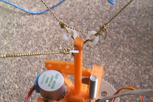
 RigTig