 Malte Schrader
The first version proved the feasibility of such a 3D printer design, but still had some design flaws in it. V1 can print with a good quality but the Z-homing accuracy is very poor that is why starting a print is always difficult. Another Problem is that
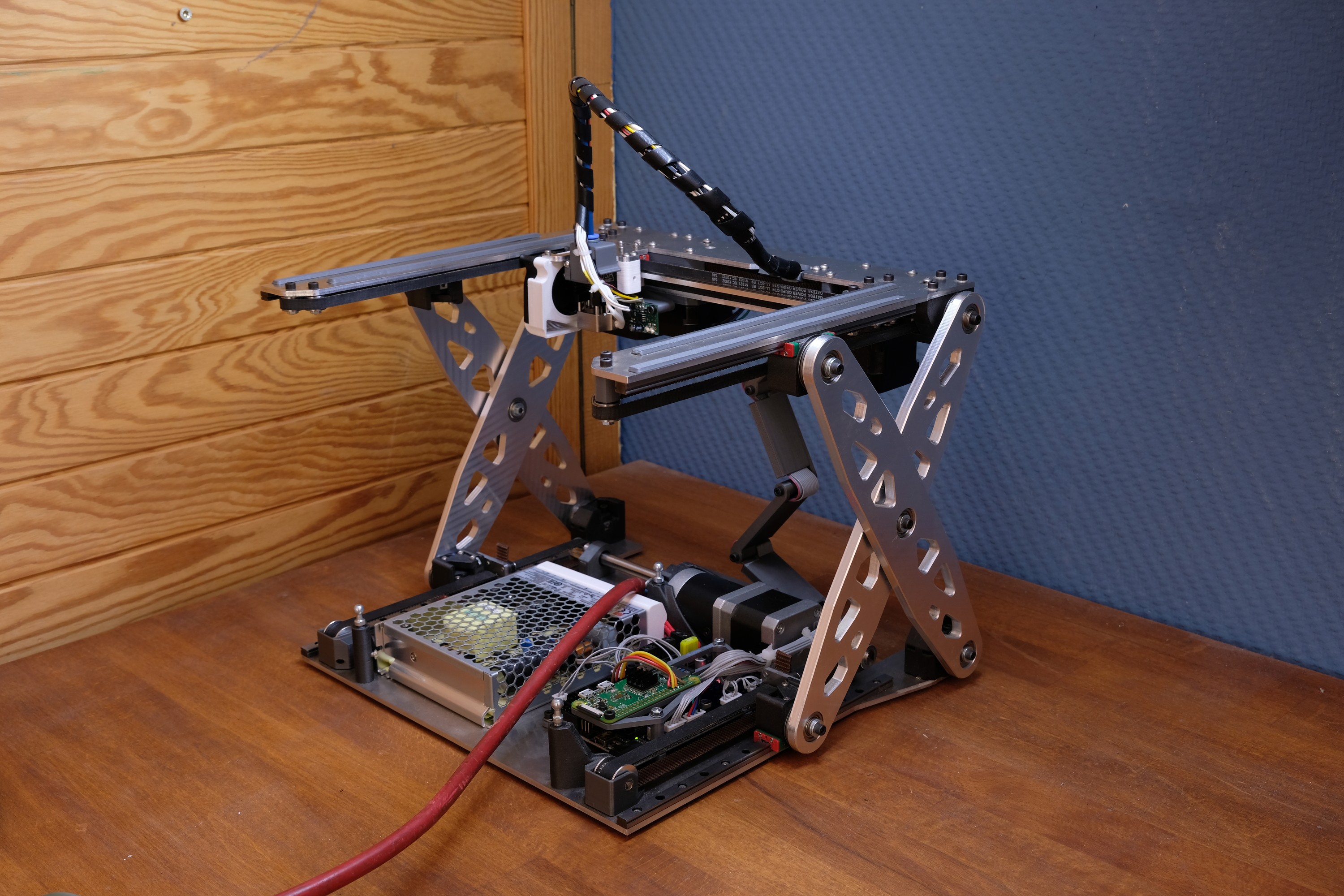
one scissor lift (left/right) could be pushed down with ease (when the printer is in a relatively tightly folded position), so that the parallelism of the X-axis to the bed is not longer given. This happens because of the large force ratio with which in general a scissor lift comes. In the previous build, the two lifts were connected by one arm and the arm was moved by the ball screw. This arm easily twisted when an uneven force on the lifts were applied, so that the left and right lifts have different heights --> results in a tilt of the X-axis.
Other points for improvement are the weight, the 3D-cnc-milled aluminium parts which it required and the dimensions of the V1 printer.
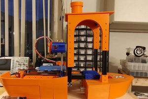
Changes V2:
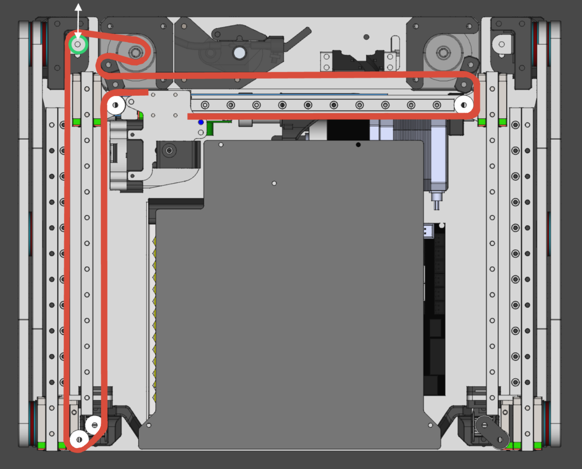
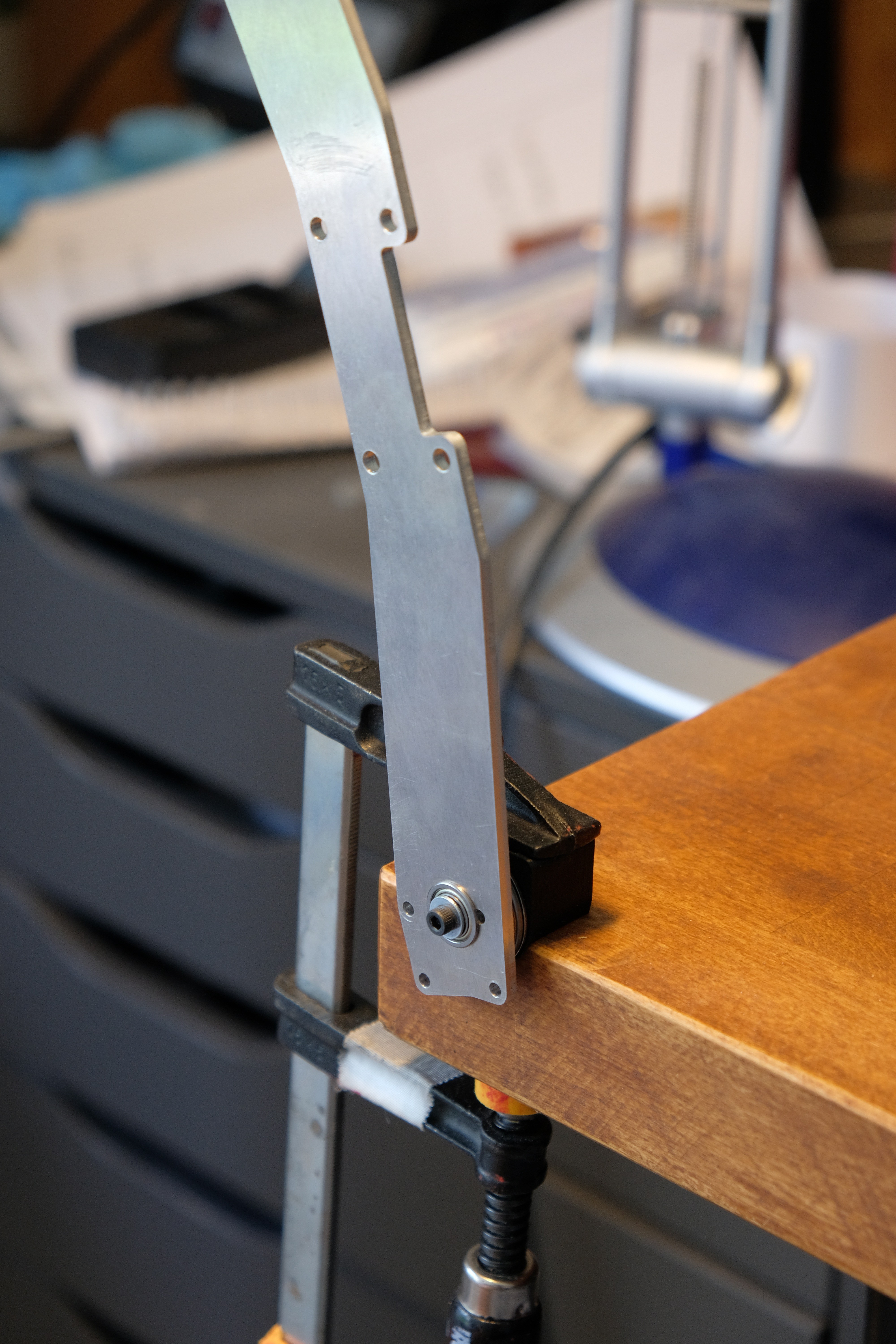
- Instead of a ball screw for the Z-axis this version will have two belts, on each side one. Driven by a geared nema17 Motor (20:1). I'm hoping that this will improve the uneven lift motion of the left and right side. Because the scissor lifts are closer connected to the motor (Z-axis) less parts can flex or twist. Belts can flex as well but I'm hoping by using two 10mm belts that this will not happen.
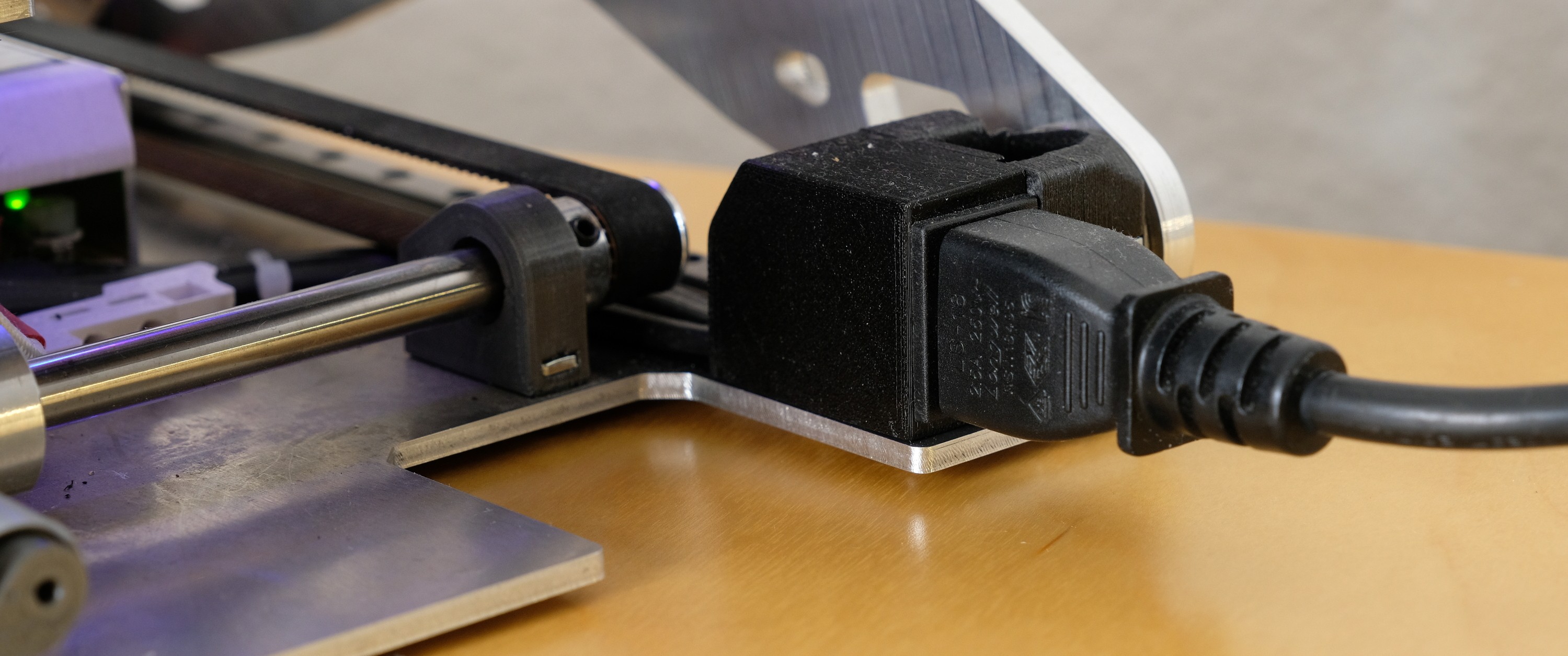
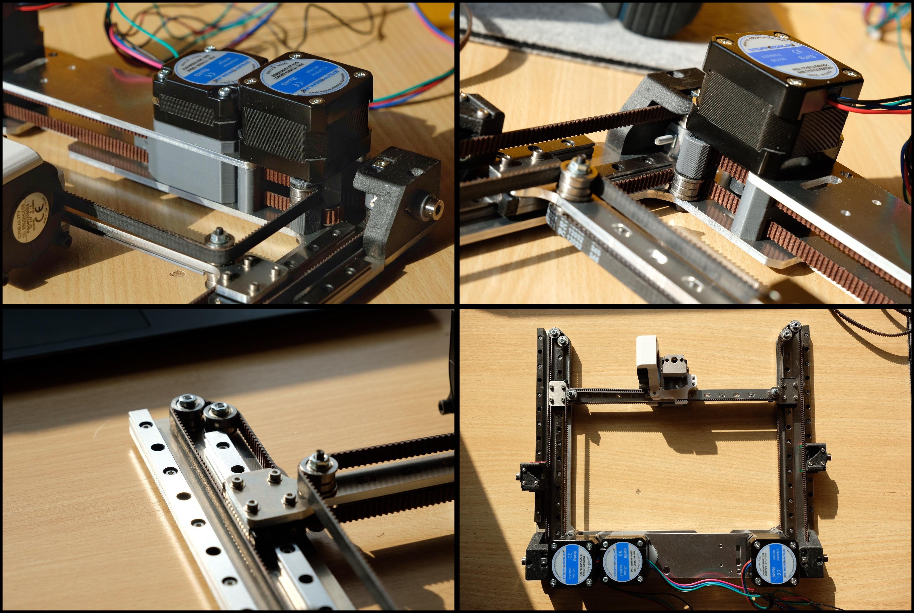
- mgn7 rails are used instead of mgn12 as in the predecessor (saves weight and space, inspired by VORON V0)
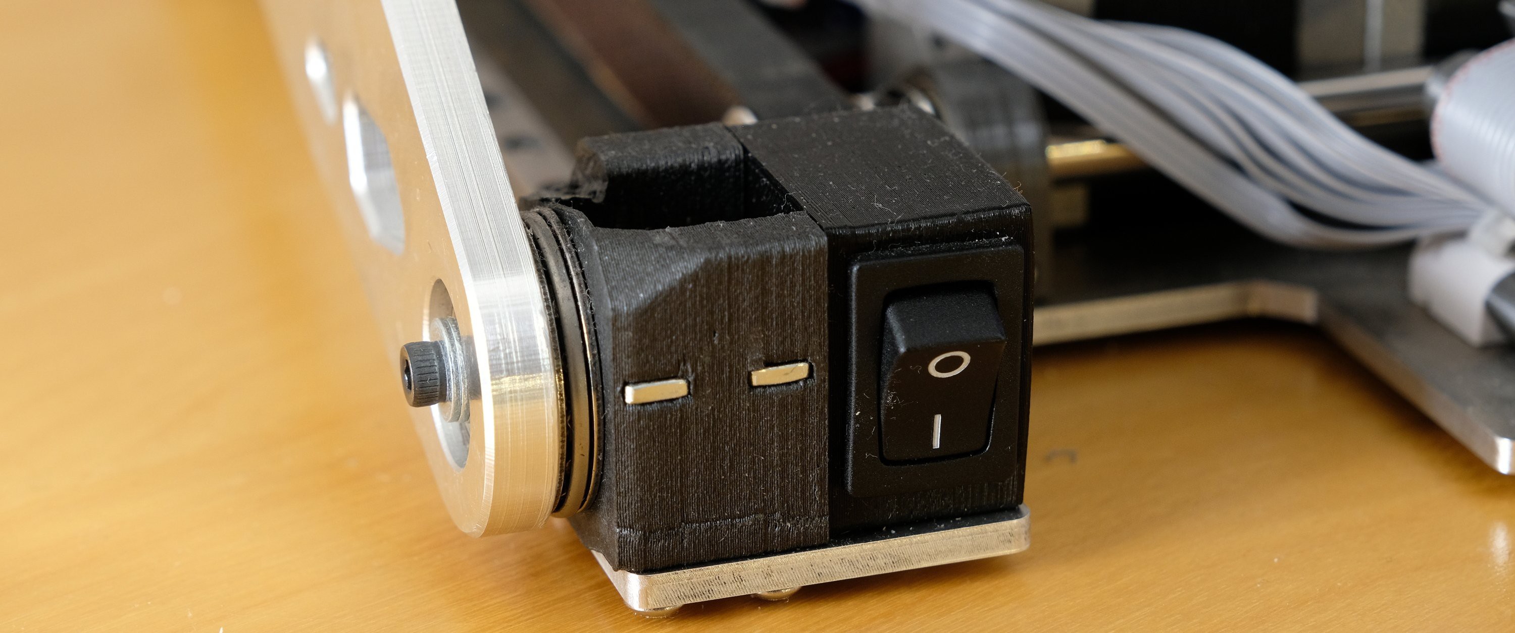
- Klipper firmware, no display.
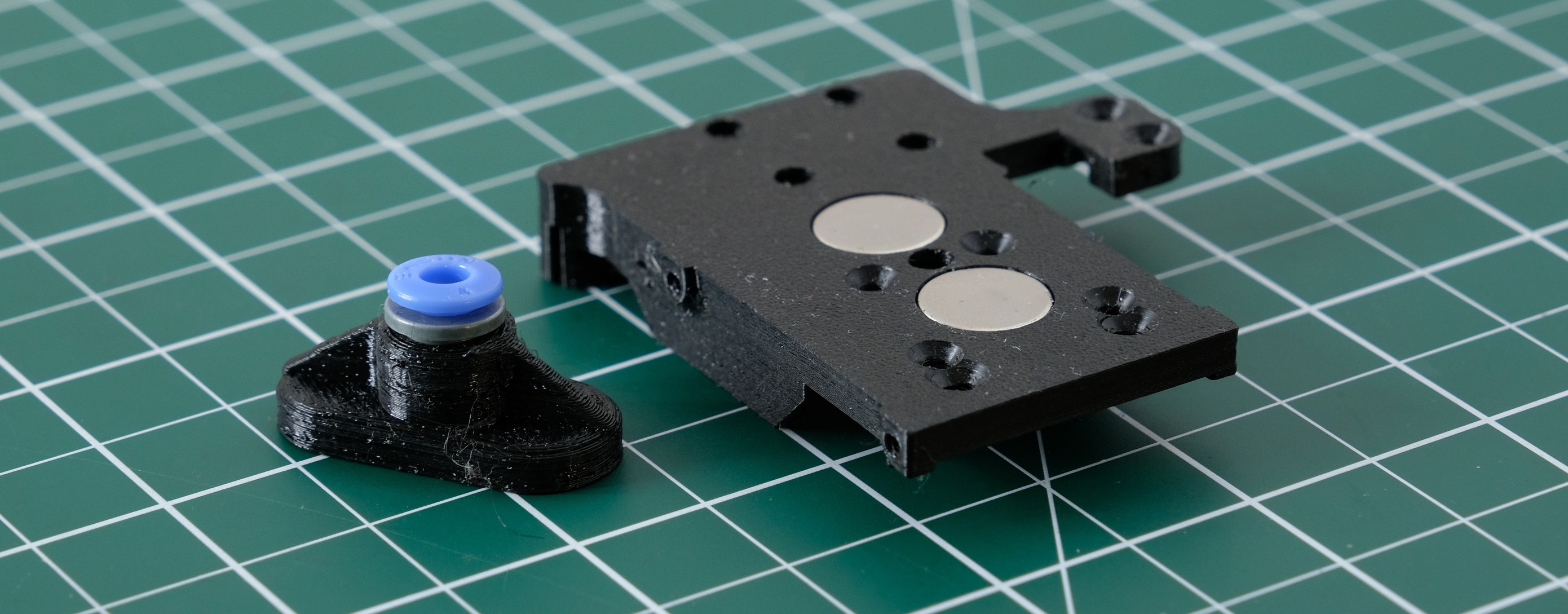
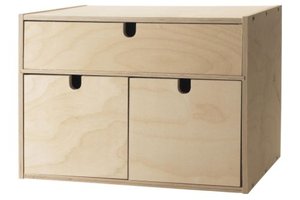
- Print bed will be kinematically mounted to the main frame. I Found it here.
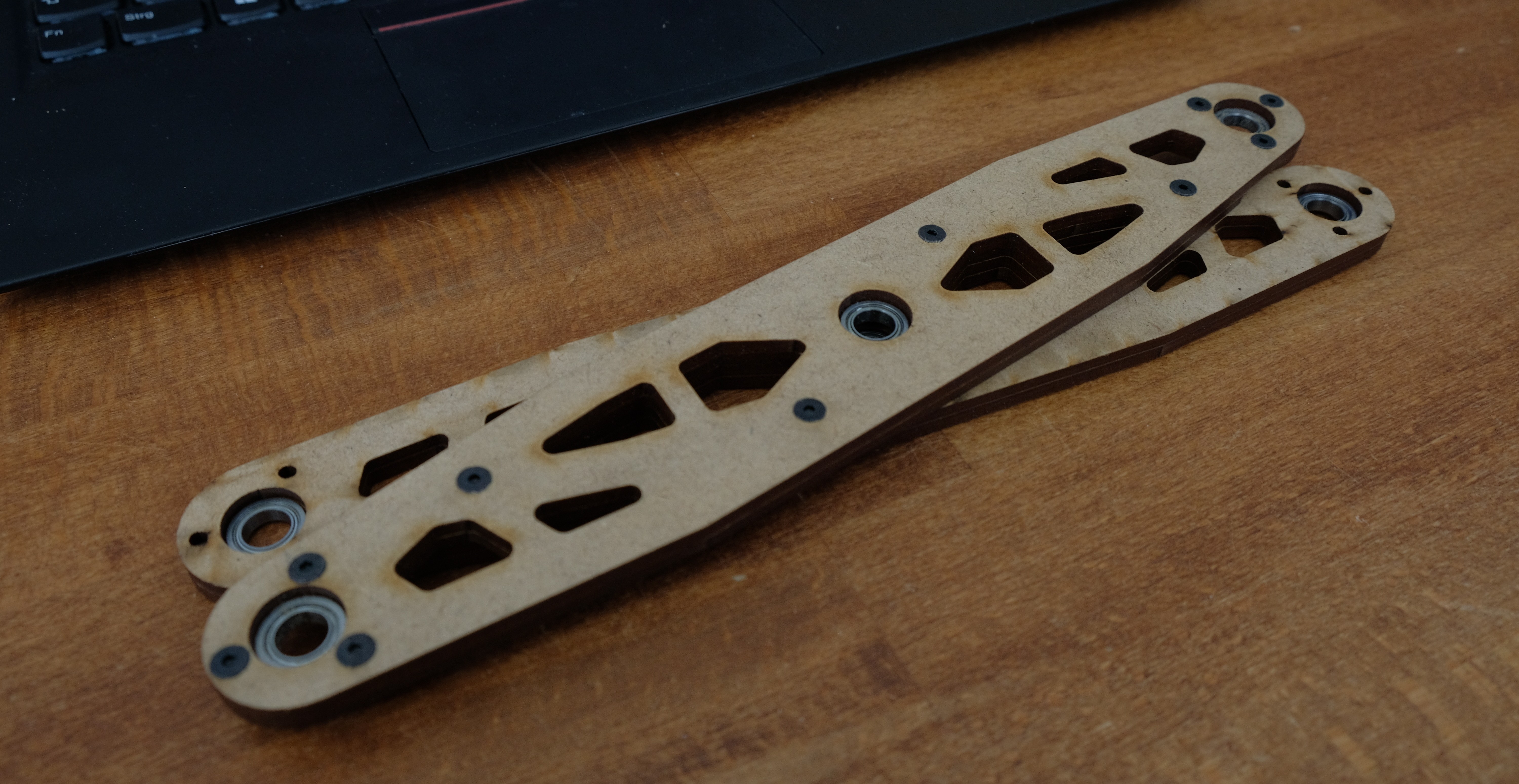
- only 3mm sheet aluminium will be used, thus the build / part-sourcing is easier.
- Axial needle bearings instead of friction ones (more uniform "friction coefficient" on the two lift systems) --> maybe improves the uneven lift motion


 the.wretch
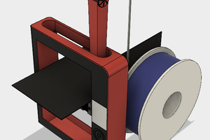
 Mo Badr
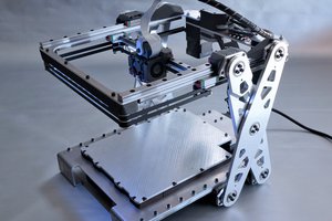
 Andrew Kowalczyk
You mention steel wire to stiffen the next iteration. If you're thinking of running rigging, also check out UHMWPE/HMPE cord. Very low stretch and very flexible for running over pulleys, etc. Brand names include Spectra or Dyneema but generics are plentiful. 1mm cord can hold close to 200kg with 3-5% stretch, so you can over-spec strength to get stretch as close to zero as you like. For fractional mm diameters, look for "braided" fishing line. Neat stuff.