So I had a project I was working on, and I saw that it fit one of the Hackaday Prize challenge rounds, the 3rd in particular.: Reimagine Supportive Tech. This includes educational projects. I have a young daughter (2.5 years old) and I wanted to introduce her to electronics gradually, and in a way that helps her understand electricity and electronics naturally and intuitively.
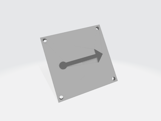
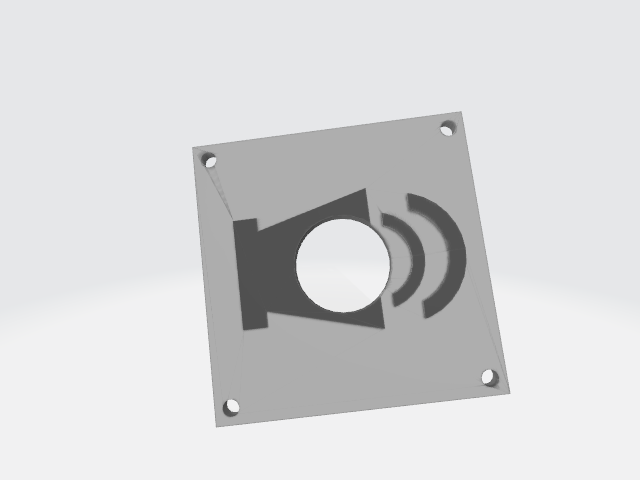
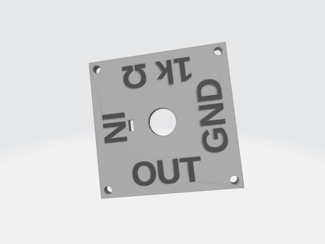
So how do we go about teaching the extremely young about electronics? My daughter just so happens to enjoy blocks and puzzles, and I quickly decided this was the best route to accomplish my goals. If I could build a lego-like system that works similar to a puzzle, I could give her some plastic blocks, show her how they fit together, and let her experiment. Of course the focus should be on the flow of electricity and not struggling to fit things together, nor should they be possible to fit together improperly since children her age often can't pay attention to too many details at once. My hope is that my idea will make learning electronics possible for the very youngest of future engineers (should they decide to go that route). At the very least, it should give my daughter a better understanding of the world she lives in.
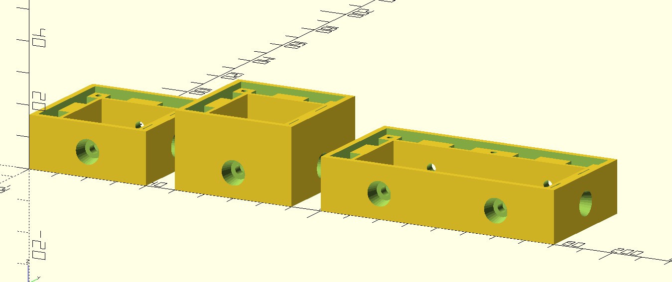
I'm releasing my project into the open domain. I have written everything in my OpenSCAD file from scratch using measurements I made myself. My goal is education. I feel that an open domain dedication is more likely to accomplish that goal than any other license. Take my work and do with it what you will. I hope you find success.
0%
0%
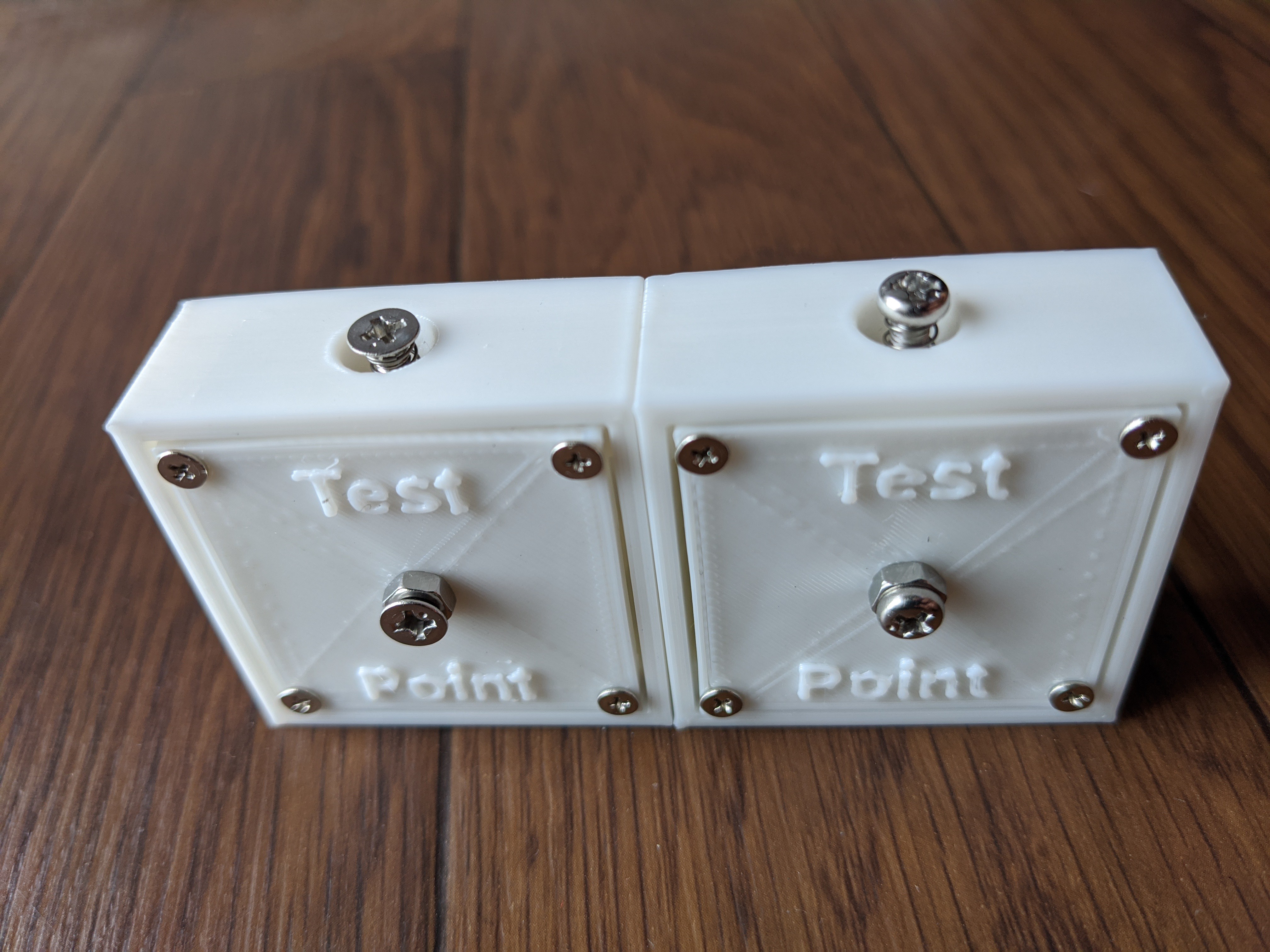
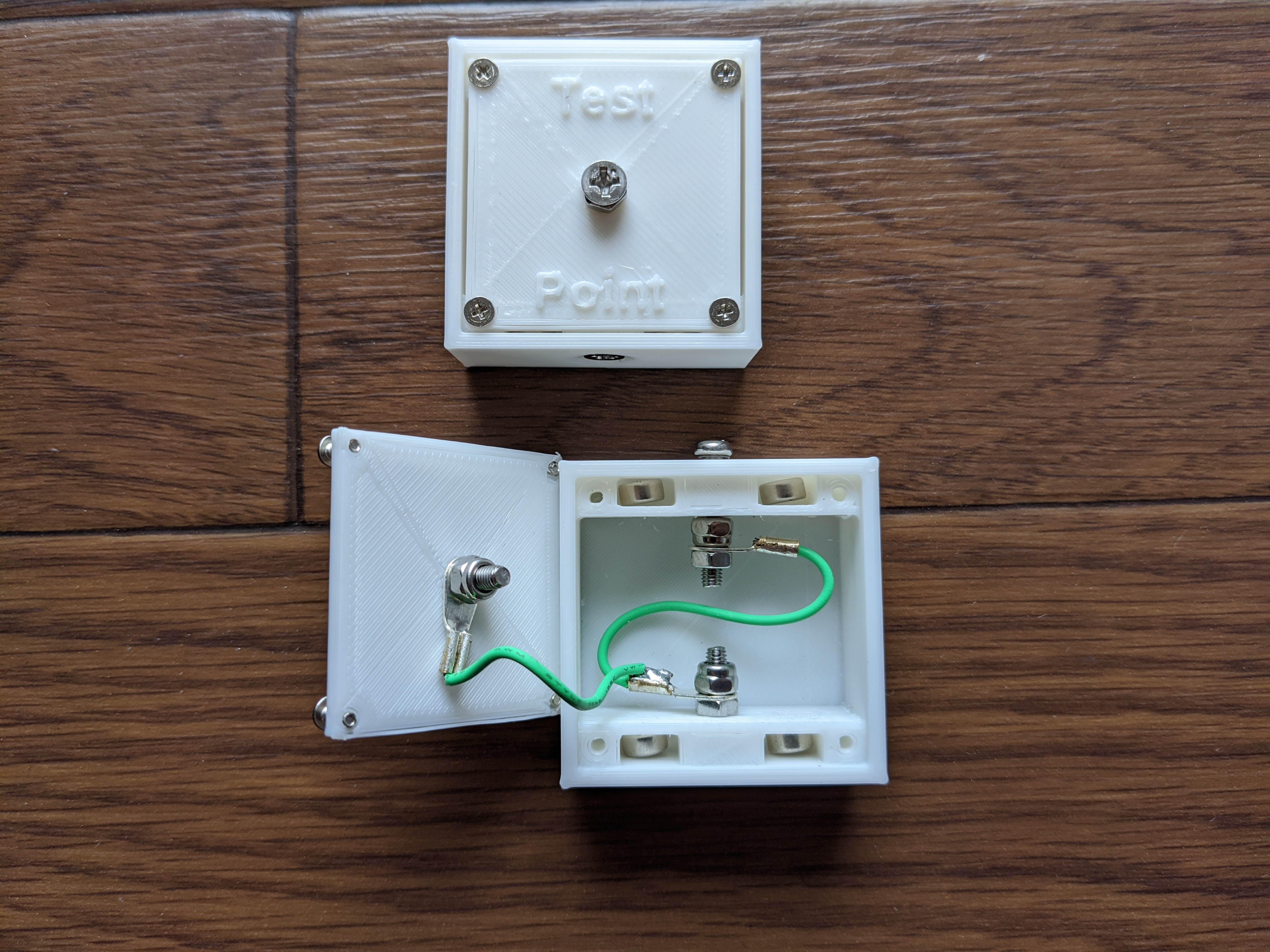
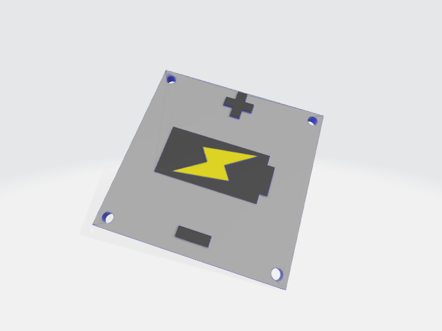
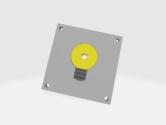
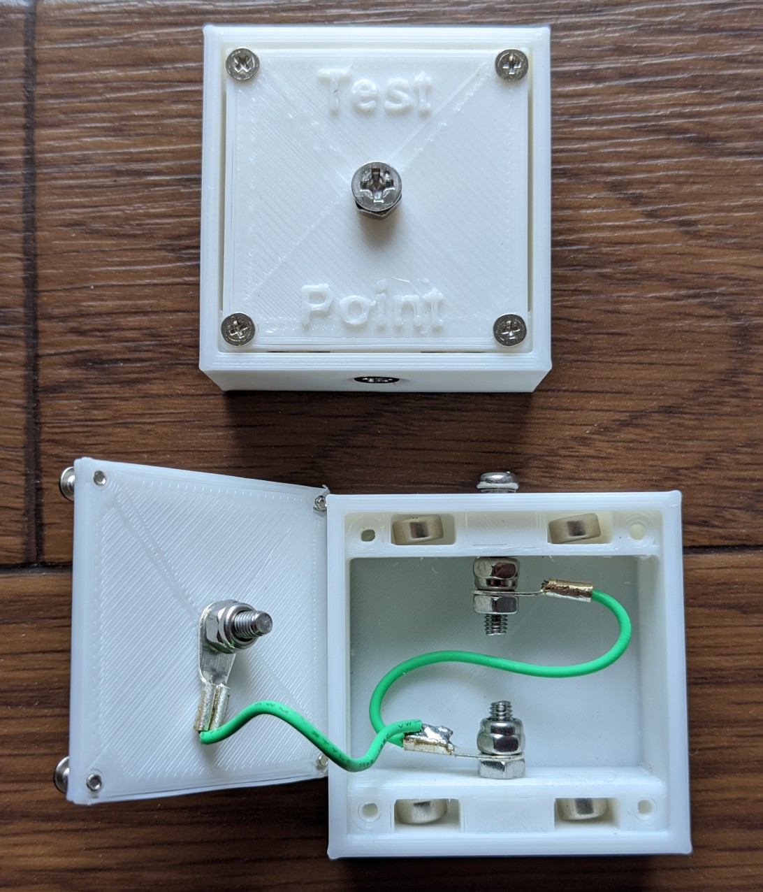
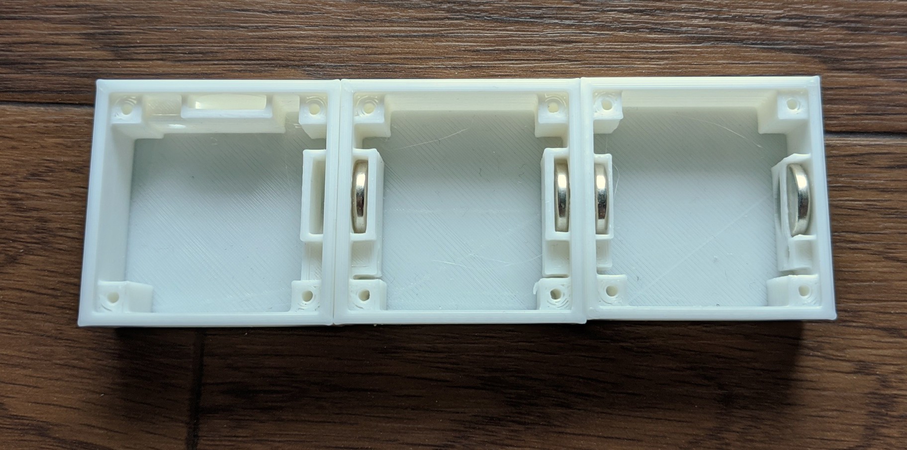
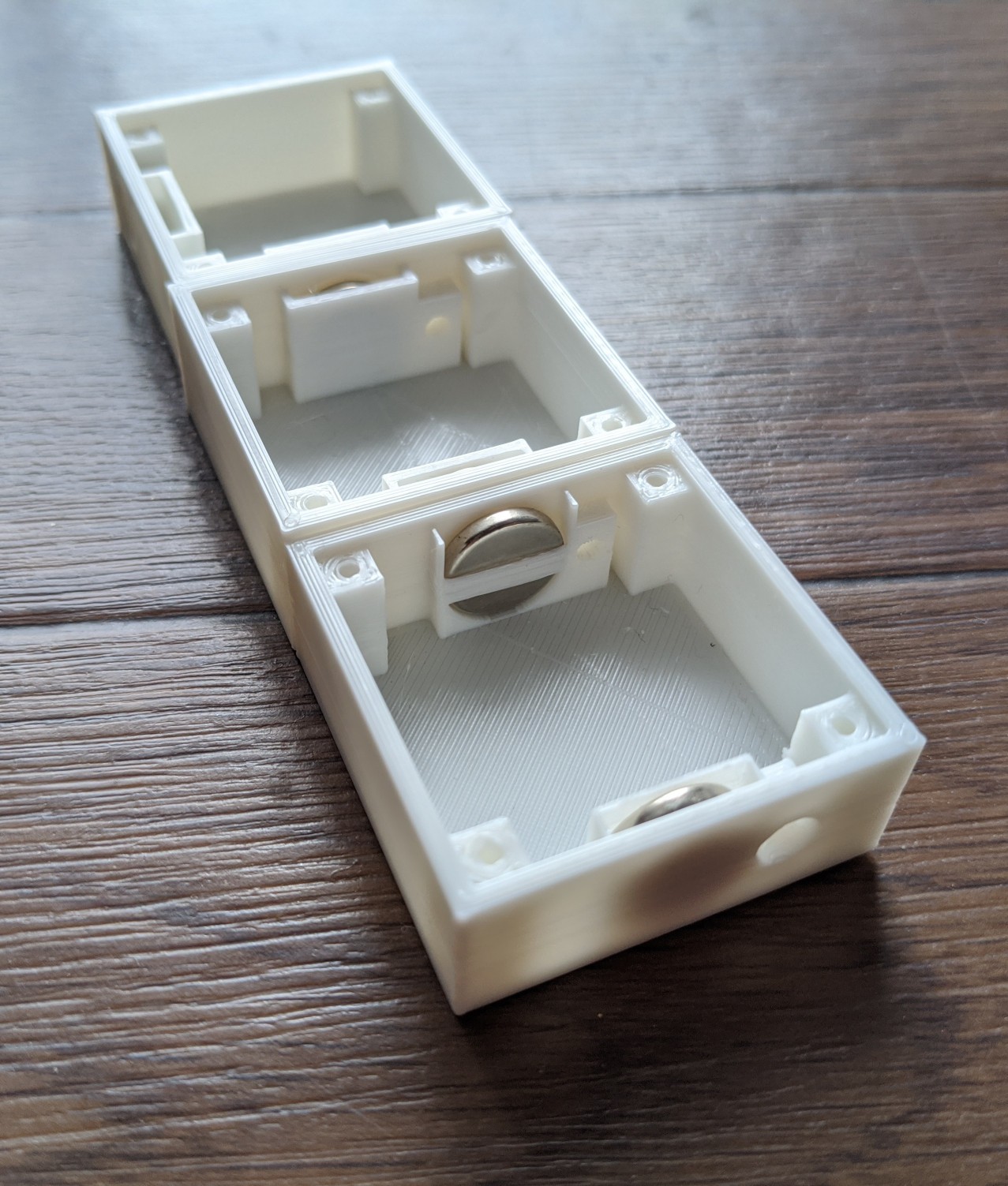
Electruzzles
Little boxes that snap together and make circuits. An excellent way for kids to explore and understand electronics.
Become a Hackaday.io member
Already have an account? Log in.
Just one more thing
To make the experience fit your profile, pick a username and tell us what interests you.
Pick an awesome username
hackaday.io/
Your profile's URL: hackaday.io/username. Max 25 alphanumeric characters.
Pick a few interests
Projects that share your interests
People that share your interests
 Jan
Jan
 joseph
 secretbatcave
Yay! I finally got comments. Too bad they're spam. wah wah waoooooh.