Robert
-
SD card support
08/30/2021 at 20:49 • 0 commentsSD card works OK, here are interesting things that I've learned:
- There are two protocols to communicate with SD card - SPI (slower, but easier) and SD bus, some cards will not work with SPI
- The SD card can draw up to 100mA when writing data!
- As usual, it's good to add small resistors in series to all pins that are accessible from external, user can insert or remove card, so all data ports can be considered to be accessible from external. This is to prevent ESD damages. For SD card those resistors are in range 40-50R.
- It's good to add pull-up resistors to all data lines, otherwise some cards will not work. There are chips on the market with pull-ups and in-series resistors.
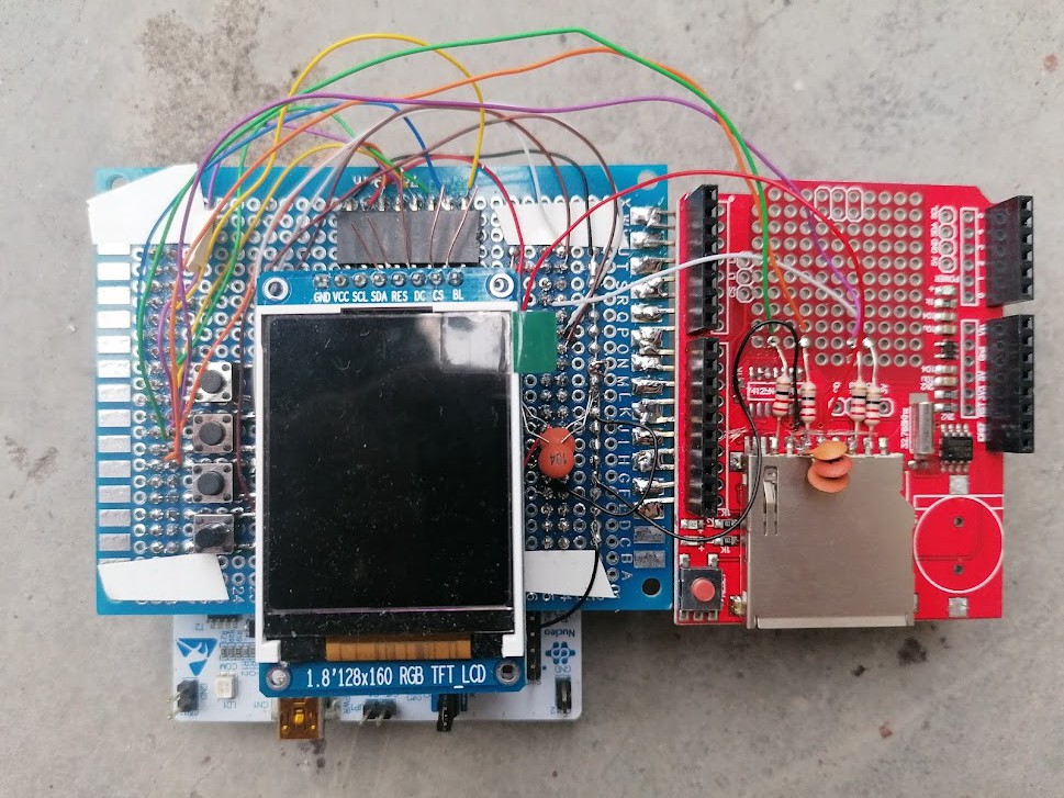
The prototype is now a bit bigger than before, because I've decided to cannibalize data logger board for Arduino - back when a shipment from China was for free (in Europe) I'v bought a couple of them - just in case. I don't really need therm since I don't do a lot of Arduino, and this saves me on buying SD card slot and RTC clock. I will add an RTC clock to the design.
![]()
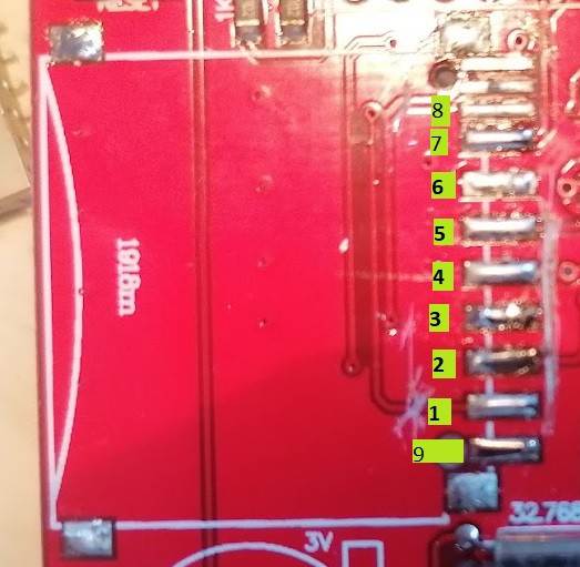
The SD slot was a bit problematic, finally I've de-soldered it to see bottom side and how the card is really connected. It's weird for me because they didn't ignore pin #9, it's accessible even when AFAIK it's unused. So the pinout is like this 9, 1, 2, ..., 8, extra pins for check write protection.
![]()
In the next step I plan to setup ESP32, it will involve probably soldering new breadboard to the prototype :)
-
Reduce amount of elements on PCB, but keep functionality
08/27/2021 at 16:39 • 0 commentsI've got a small success in reduction of amount of components on the PCB, I tested it on the breadboard -presented before- and i works fine.
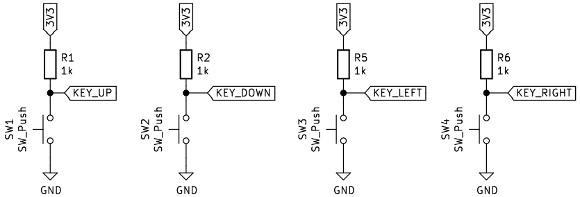
First, I tried to remove the pull-up resistors for switch buttons, below is the original diagram. BTW note that on this schematic there is no low pass RC filter, the filter is used for key de-bouncing, it's used in many open hardware projects, but this can be done in software too.
![]()
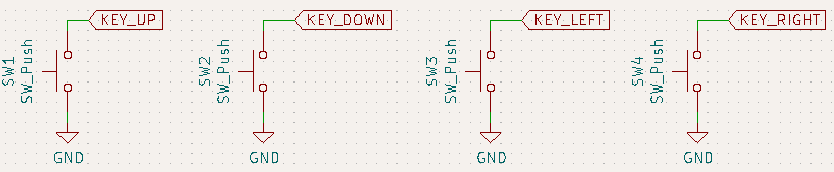
Below is actualized version.
![]()
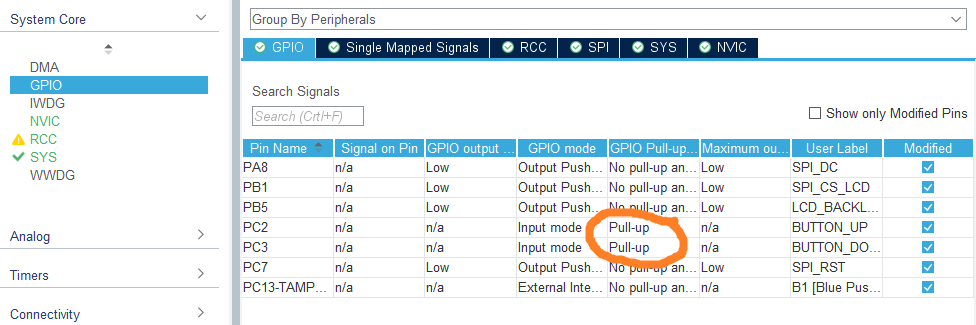
This is possible because STM32 has possibility to configure GPIO as having internal pull-up resistor (it can be an internal pull-down too), so this resistor is still on the schematic, but now I'm using the one build-in into the microcontroller.
Below you can see it on CubeMx.
![]()
Note: I still didn't decide to which GPIO connects the key-left and key-right, so those are not configured.
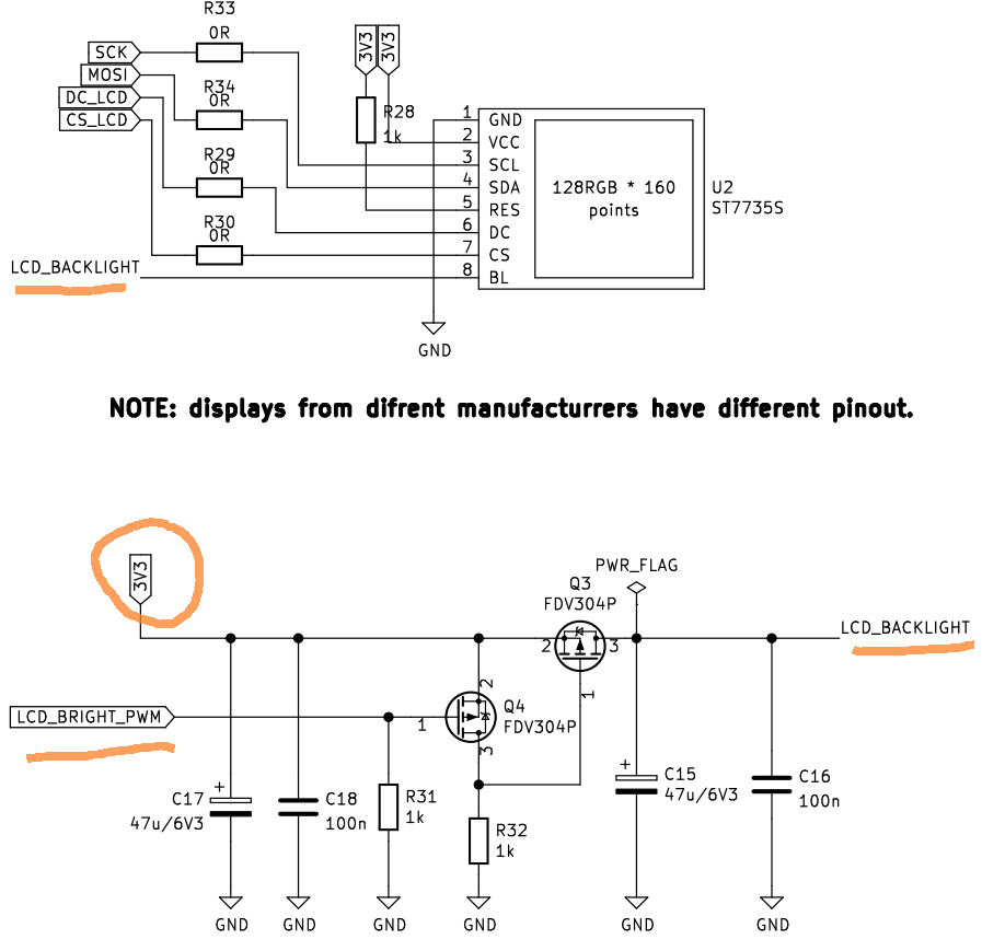
Another IMHO cool optimization is in setting the brightness of the LCD, originally I've planed to use discrete solution that would be driven by PWM. The ST7735S LCD module has a separate pin for LCD brightness, I was thinking that the actual current for backlighting is needed to be provided to this pin. This is not true, it's just a logic signal, that goes to the SOT-23 chip on ST7735S.
The previous version is presented below.
![]()
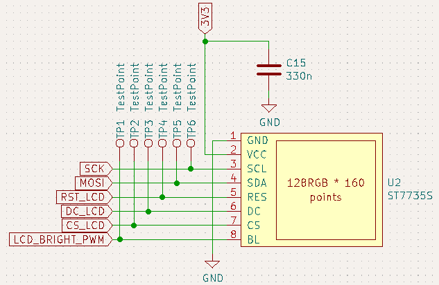
All the bottom part might be removed, because very little current is in real taken from GPIO port and there is no need for buffering transistors Q3, Q4. The buffering is done by small chip on the LCD module. Below is the current version.
![]()
I've also been able to communicate with the LCD. Fun fact is that initially I used this lib for ST7735S, but I didn't notice that it's for 80x160 displays. Mine is 128x60. Fortunately, I've found this lib for ST7735 - this one handles my LCD well. From the other side, invocations of HAL functions are a bit hardcoded with business logic, so in order to bring my PC variant for simulation of the device to live, I will have to do a bit of refactoring.
My next steps will be checking circuit for SD card.
-
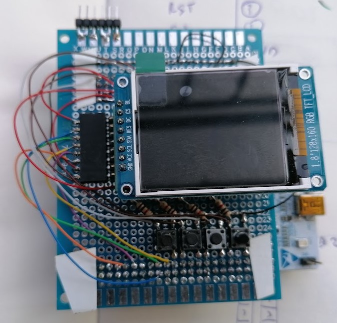
Bread-board circuit for testing LCD and keyboard
08/25/2021 at 14:51 • 0 commentsI've created a draft of the device using bread-board to check if I correctly connected LCD to stm32 nucleo and to have something to do driver development before ordering PCB. In addition I've added to the board up/down/left/right keys.
Connections changes to original schematic:
LCD connection:
- RST - PC7
- DC - PA8
- CS - PB2
Keys:
- up - PC3
- down - PC2
- left - PC14 (TODO: move it somewhere else)
- down PC15 (TODO: move it somewhere else)
I've also tried to solder the part responsible for dimming the LCD but having only MOSFETs in SOT-23 package, it seems to much to work.
![]()
Data Logger Shield
Shield for NUCLEO-F103RB, it's a logger of pulses received from four external devices. Has WiFi, sdCard, keyboard and LCD.