 Pariv
Pariv
Powertrain System Overview:
The Powertrain system of our Electric Vehicle comprises High Voltage Systems, Low Voltage Systems and Drivetrain systems.
- Drivetrain Systems: The drivetrain system of a vehicle is a system that transmits power from the motor to the wheels. We use an Emrax 228HV motor as it provides high torque whilst also being extremely efficient. The torque from the motor is transmitted to the differential by a chain drive system. The differential is a crucial component that plays a major role in the car's performance in acceleration as well as cornering , hence we use a Drexler FSAE V2 differential which is a 1.5 way clutch-type limited slip differential with an adjustable torque bias ratio. Tripod type CV joints and half shafts are used to transmit the torque from the differential to the hubs/wheels.
- High Voltage Systems: It consists of the battery, motor controller and motor. The tractive system electronics department looks after the battery management system, the high voltage block diagram and other safety circuits and systems required for the functioning of the battery. The high voltage block diagram consists of the fuse, the accumulator isolation relays, the battery and the motor controller. The department deals with the charging process and the calibration of the motor controller. The mechanical integration department works on the designing, assembly and manufacturing of the battery.
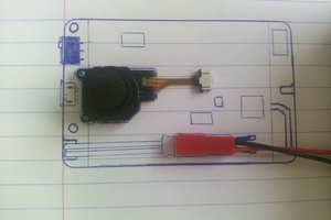
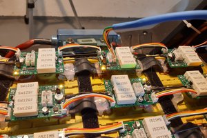
- Low Voltage Systems: The Low Voltage system operates at 12V and generally consists of the circuits used for the safety of the car and the acquisition of sensor data and telemetry. The safety circuits used on the car are self-designed rule compliant circuits. A separate Data Acquisition System is present on our Car which consists of the transfer of data from various sensor/transducers to our custom DAQ Data Logger using CAN Protocol. Our data is then stored and displayed using SD Card, USB Module, WiFi Module and RF Wireless Module on our DAQ GUI.
The process of PCB Designing follows multiple stages which are followed during the season.
- We first start off by deciding the goals of the season and start the research and concept phase according to these goals.
- After the goals have been decided and the research regarding the corresponding goal is completed, we move ahead with the selection of the components which are going to be required in the designs.
- Selected components are then used for logic creation and designing of the circuits. A detail analysis is done while selecting every component.
- These circuits are designed and simulated in various simulation software to validate the designs.
- Following that, we carry out the breadboard testing for all the designs to estimate the practical working of the circuit and components.
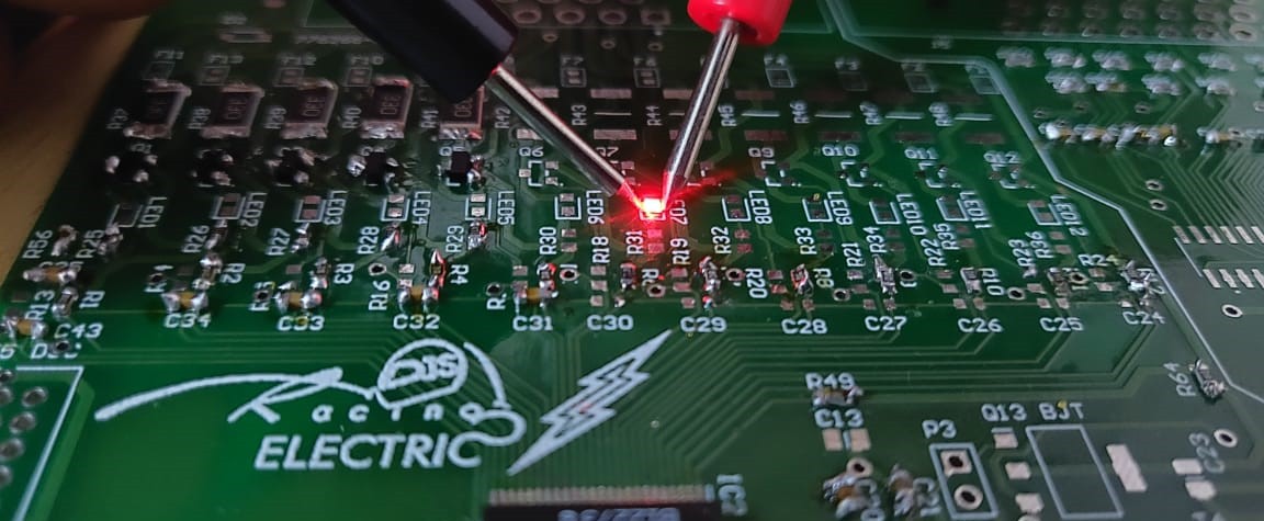
- As the expected output from the breadboard testing is received, we go on towards the designing of the final PCBs in the software. Its schematic is designed and routed according to our current requirements. The Gerber files are then sent to JLCPCB and within 7-10 working days, we receive manufactured PCBs from JLCPCB. Meanwhile, all the components are procured and then soldered on the PCB which is followed by a thorough testing and analysis of PCBs with respect to time, temperature and power. These tested PCBs after clearing the testing process are used in the car various purposes.
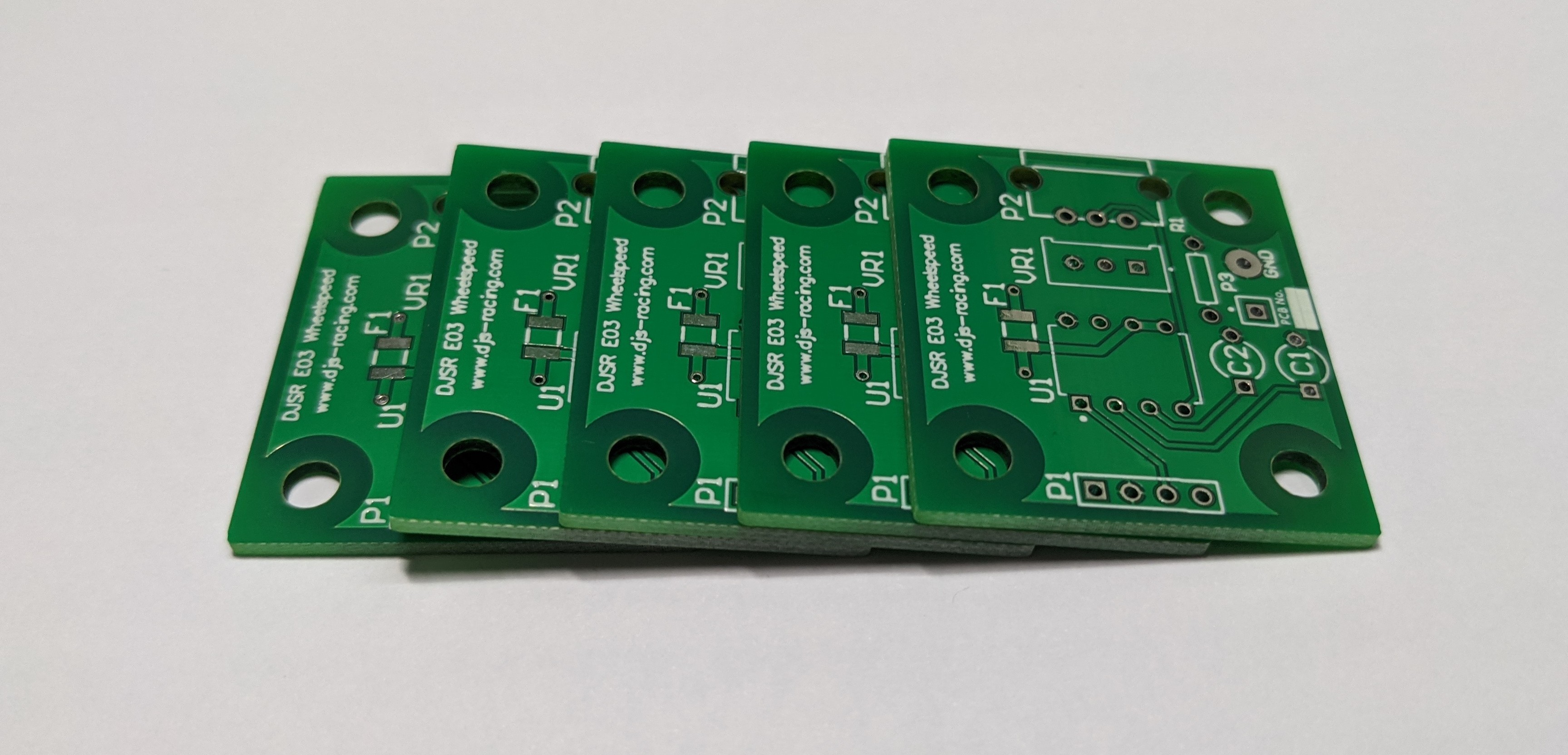
We choose the JLCPCB because offers fast, high-quality service at reasonable prices.
- To order visit JLCPCB & sign-in/sign up.
- Click the "quote now" button.
- Click on the “Add your Gerber file” button and upload your Gerber files Now you can set your parameters and customizations, such as quantity and PCB colour
- Click “SAVE TO CART”
- Go ahead and type your shipping address, choose the shipping method
- The process to submit your order and payment
- The PCBs our team ordered came within the week.
 Alvaro Ferrán Cifuentes
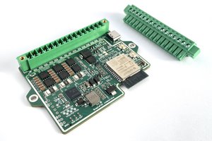
 Sergio Ghirardelli
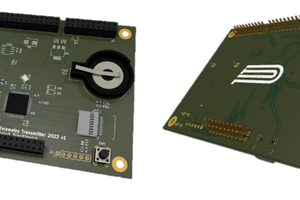
 PUTMotorsport