mras2an
-
Some news!
10/09/2021 at 09:52 • 0 commentsCurrently, three peoples are use the VinyGo board on their own vinyl recorder.
On top of that, one company has adapted its vinyl recorder to use it with the VinyGo board.
Two people from the Hackaday community started building all the VinyGo system. I am looking forward to see photos. One of them found a synthetic diamond manufacturing company for vinyl recorders. The costs of the synthetic diamond is about $ 12 instead of $ 100 (but we have to rework it). However, this is revolutionizing and makes the price of the VinyGo system cheaper.
A friend of mine has also started to build VinyGo system.
-
11) Getting started and functioning
08/29/2021 at 20:14 • 1 commentYou have to clone VinyGo git repository: git clone https://github.com/Mras2an/VinyGo.git
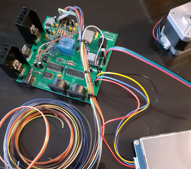
11.1) Hardware connection
11.2) Compile and program the code
See log 9) Flash and build ESP32
11.3) First boot
1 - Power on the VinyGo board, You see the LCD test menu.
2 - Click on it, and check all the tests (sensors, and commands). If it OK return to the menu
3 - Go to the calibration menu and make your calibration for 7, 10, and 12p vinyl.
4 - The system is ready, enjoy :-)
-
10) List and cost of components
08/29/2021 at 19:49 • 0 commentsPC
~ 200 $
Turntable (you have to use direct drive whit high torque and not belt drive)
~ 250 $
Mix table
~ 50 $
Ampli
~ 50 $
PreAmpli
~ 50 $
VinyGo board with motors, sensors and LCD
~ 117,37 $
VinyGo mechanic with diamond and 120W audio tweeters (if you have 3D printer)
~ 230 $
Cables (RCA, MIDI, Jack)
~ 30 $
Total
977,37 $
-
9) Flash and build ESP32
08/29/2021 at 19:44 • 0 comments9.1) On GNU/Linux
$ cd VinyGo/03_Software/ESP32/
$ export IDF_PATH=$PATH/esp-idf/
$ export PATH="$PATH:$HOME/Project/esp32/xtensa-esp32-elf/bin"
$ make
9.2) Flash ESP32
9.2.1) On GNU/Linux
link on binaries: https://github.com/Mras2an/VinyGo/tree/master/03_Software/ESP32/build
$ python esptool.py --chip esp32 --port /dev/ttyUSB0 --baud 115200 --before default_reset --after hard_reset write_flash -z --flash_mode dio --flash_freq 40m --flash_size detect 0x1000 $PATH/bootloader.bin 0x10000 $PATH/VinyGo.bin 0x8000 $PATH/customPart.bin
9.2.2) Via Wifi (only if you have already done 9.2.1)
- download python 2.7.12 : https://www.python.org/downloads/windows/
( https://www.python.org/downloads/release/python-2712/ )
- Click on update in the VinyGo update menu (lcd).
- Connect your PC at wifi “HRC” password “HRC2yBqT”
On your PC execute the commands:
GNU/Linux
$ python $PATH/update_firmware.py 192.168.52.1 $PATH/VinyGo.bin
Windows
C:\Users\Desktop\VinyGo>py update_firmware.py 192.168.52.1 VinyGo.bin
or
C:\Users\Desktop\VinyGo>python update_firmware.py 192.168.52.1 VinyGo.bin
connecting to 192.168.52.1...
connected, socket = <socket._socketobject object at 0x02582EA0>
sending 'start OTA' command to target...
sending fragment 1 of 125 (4096 bytes)
...
-
8) Flash LCD Nextion
08/29/2021 at 19:37 • 0 comments- Open project with Nextion editor (link: https://github.com/Mras2an/VinyGo/tree/master/03_Software/LCD_Nextion)
- Connect the USB/RS232 cable at PC and on Nextion LCD (Rx, Tx, GND)
- In Nextion editor click on Update -
7) Software
08/29/2021 at 19:32 • 2 commentsThere are two micro-controllers on VinyGo. The master uses an ESP32, and the slave uses a stm32 for the HMI on the LCD touchpad. Both communicate via an UART protocol.
It can be downloaded on the VinyGo git project. https://github.com/Mras2an/VinyGo/tree/master/03_Software
7.1) UART protocol
I created an UART protocol for the slave and master communication. Each frame is made as follows:
Frame example to enter in system mode: 0x55 42 53 06 53 79 73 74 65 6d 54
Start byte
Header byte
Command byte
Data size
Data
End byte
0x55
0x42
0x53
0x06
0x53 0x79 0x73 0x74 0x65 0x6d
0x54
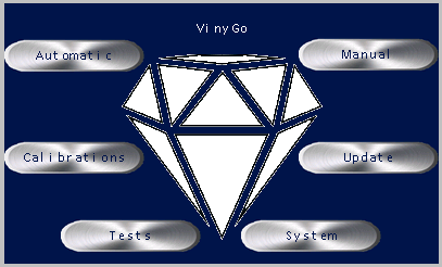
7.2) IHM on LCD touchpad
I chose a Nextion LCD touchpad and Nextion editor v0.53. With this LCD screen, we can design an HMI simply with drag and drop. Each text and button uses the UART protocol seen above.
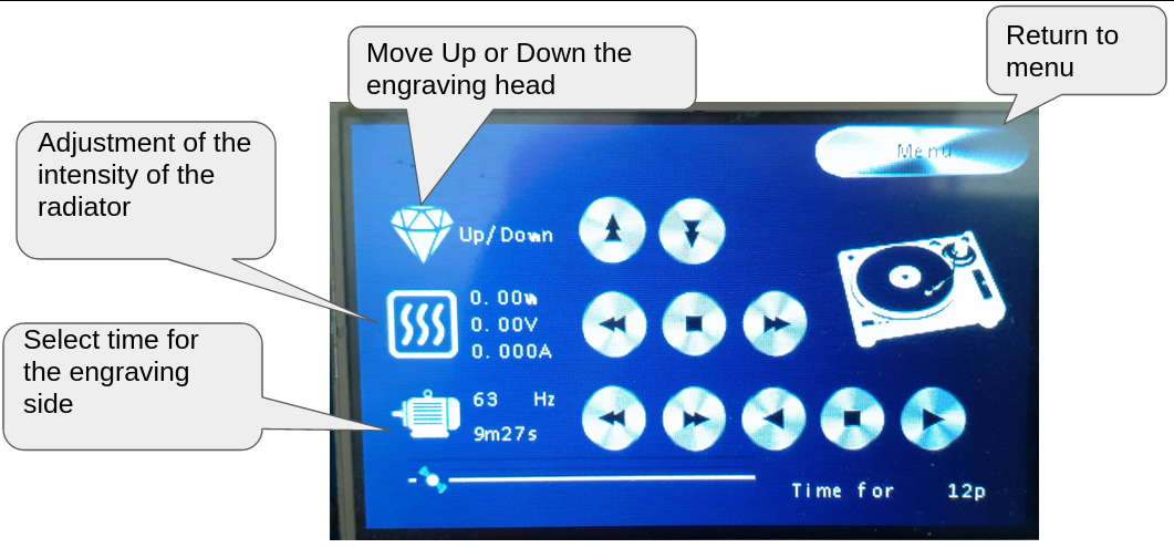
7.2.1) Manual mode
With the manual mode we can adjust all the parameters of the burner one by one, like motor speed, stylus heating.
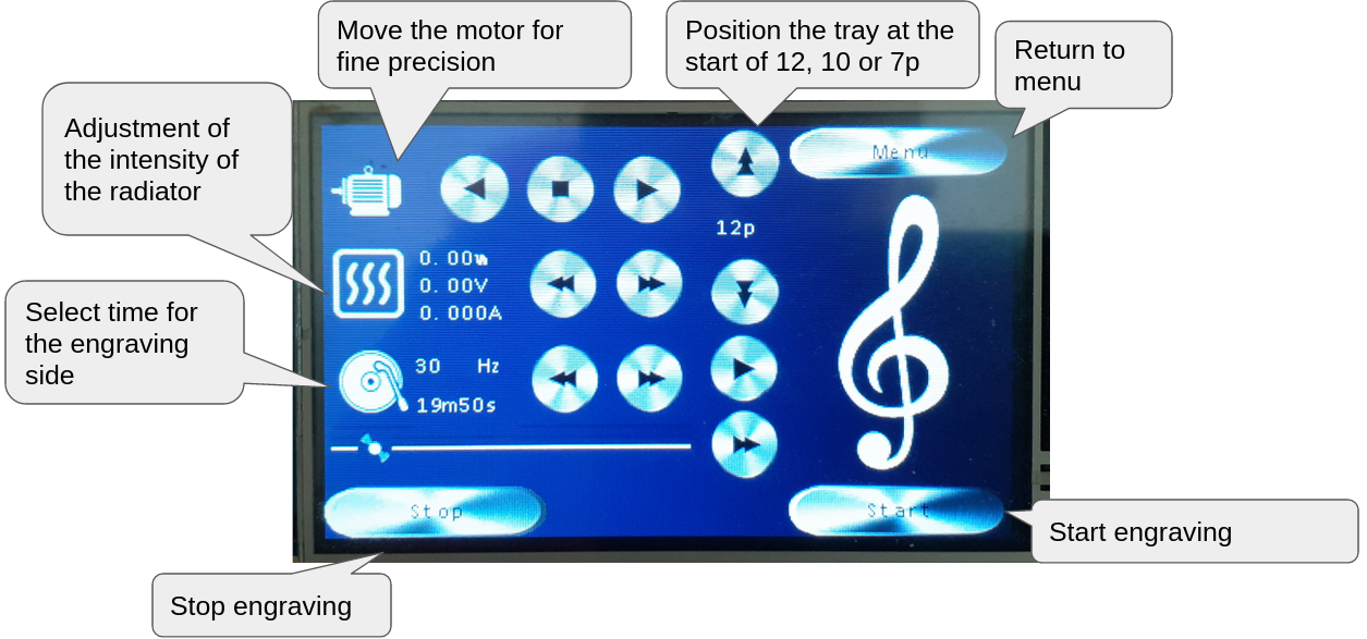
7.2.2) Automatic mode
With the automatic mode we just need to choose the vinyl size (7", 10", 12") and the time of your playlist. After that all is made automatically. The MIDI commands received in this mode increase or decrease the motor to create the start, middle, and end groove on the vinyl.
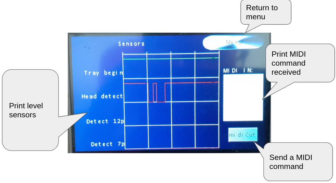
7.2.3) Test mode
If you have operating issues this mode is for you. You can test all sensors and commands.
7.2.4) Update mode
Very useful to send an update on VinyGo by OTA. VinyGo create its own AP, once connected to it you can send new software with a python tool (https://github.com/Mras2an/VinyGo/tree/master/03_Software/Utils)
7.2.5) System mode
System information like RAM, AP, ...
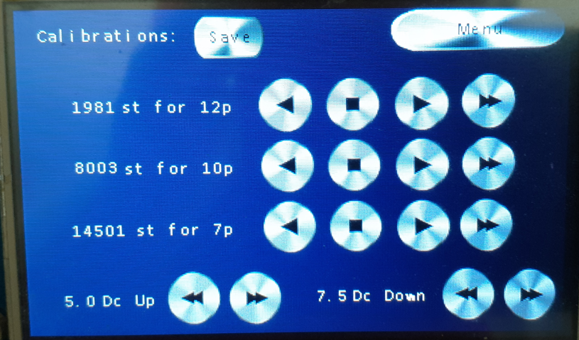
7.2.6) Calibration mode
VinyGo board is designed for several mechanics, so if you have your own mechanic you can use this mode to define the start of a 12, 10 or 7p vinyl.
7.3) Master
7.3.1) WROOM-32 module
I chose the Wi-fi WROOM-32 module because this module has a nice memory capacity, a simple and complete SDK with a lot of examples. It is also very practical to update the binary by OTA to avoid having to connect wires during the development phase.
7.3.2) SDK-IDF
I chose SDK-IDF on the v3.1 branch. The SDK-IDF has a lot of contributors. It is available on github: https://github.com/espressif/esp-idf.git
7.3.3) Flash partition
To allow the update of the system via the wifi we need more partitions. Espressif proposes the possibility to create a cvs file to define the addresses. Here is the one of the VinyGo:
# Name, Type, SubType, Offset, Size, Flags
otadata,data,ota,0xd000,8K,
phy_init,data,phy,0xf000,4K,
factory,app,factory,0x10000,1M,
ota_0,app,ota_0,0x110000,1M,
ota_1,app,ota_1,0x210000,1M,
nvs,data,nvs,0x315000,500K,
So we have a partitioned memory as follows:
| Addr | Binaries
-------------------------------------
| 0x001000 | Bootloader.bin
| 0x008000 | Partitions.bin
| 0x010000 | Factory.bin
| 0x110000 | OTA_0.bin
| 0x210000 | OTA_1.bin
| 0x315000 | NVS (500Ko)
| 0x3F0000 | Free
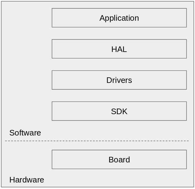
7.3.4) The architecture
7.3.4.1) The Espressif SDK
The SDK used is the SDK-IDF on the v3.1 branch available on github at (https://github.com/espressif/esp-idf). This is the official development system of the ESP32 chip.
7.3.4.2) The drivers
Used for different hardware interactions such as motors, or the functionality of the WROOM32 module (Gpio, wifi, OTA, UART, PWM, ...).
7.3.4.3) The HAL and OSAL
HAL and OSAL allow simple porting of VinyGo to another SDK, OS, or hardware platform.
7.3.4.4) The application
This is the VinyGo application. We found six modes, manual, automatic, test, update, system, and calibration accessible by the LCD. For more detail of these modes, see “IHM on LCD touchpad” chapter.
7.4) Mastering music
For mastering the music you have several possibilities, use Pro software like Cubase, use Free software like Audacity. Whatever software you use, the principle is the same. We need to filter the sound before. For that we need an iRIAA equalization. RIAA equalization is a specification for the recording and playback of phonograph records, established by the Recording Industry Association of America (RIAA). The purposes of the equalization are to permit greater recording times (by decreasing the mean width of each groove), to improve sound quality, and to reduce the groove damage that would otherwise arise during playback (If this chapter interests you, you can read more about RIAA on the internet).
Here is an example of a record without iRIAA and with iRIAA. We have too much bass, the head jumps. We can see the issue on the photo below:
Bad mastering (too much bass)
Good mastering
7.4.1) Create calibration filters for mastering
If you burn a vinyl without mastering, you will see that the spectrum of the original music is not the same that your music engraved. To have the same audio spectrum you need to create filters with iRiaa and an equalization.
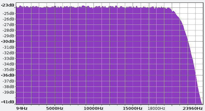
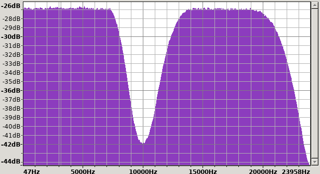
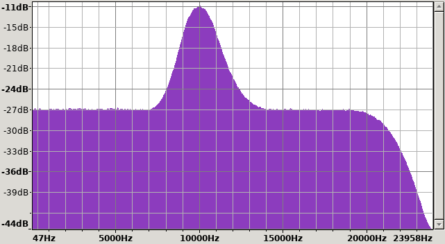
To create these filters you need to burn white noise (White noise is a random signal having equal intensity at different frequencies, giving it a constant power spectral density) (download it in VinyGo/utils git). After the engraving, it must be re-recorded and you need to compare the spectrum between the original signal and the engraved one. If there are some differences in spectrum on a frequency (example 10 KHz below) then the equalizer must be used to increase or decrease the intensity of the original signal on the frequency. That is the mastering! Repeat the operation to get the same spectrum between both original and burn signal. When it is OK you can save your filter. Use the filter on your playlist before each burn. If you use Audacity software these steps are manual, with Pro software like Cubase and fabFilter, the equalization will be calibrated automatically.
Note: Increase or decrease the amplification sound to get a sound at 0dB on your vinyl
Spectral representation of original white noise:
Example of signal attenuation on vinyl after white noise engraving (On 10KHz).
Example of original white noise equalization to increase the signal intensity (On 10KHz).
-
6) Mechanic V2
08/29/2021 at 19:26 • 0 commentsAll these STL files can be downloaded on the VinyGo git project. https://github.com/Mras2an/VinyGo/tree/master/01_3D%20Modeling
This mechanic is in the testing phase, this is why I am not presenting it at the 2021 Hackaday price. It just to show that the project is evolving for a better version. it is optimized to reduce the number of 3D parts.
-
6) Mechanic V1
08/29/2021 at 19:23 • 0 commentsAll these STL files can be downloaded on the VinyGo git project. https://github.com/Mras2an/VinyGo/tree/master/01_3D%20Modeling
This mechanic works well, it is a proof of concept but we have lot of small 3D pieces to print.
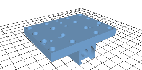
6.1) Structure
6.1.1) Standard mechanical pieces
Standard pieces for the structure can be purchased on the internet, here is the list:
- Profiled aluminum 40x4cm
- Worm screw 50cm, (diameter : 8mm)
- Ball bearings
- Steel rod 50cm, (diameter : 8mm)
- Worm (M4)
6.1.2) 3D pieces example
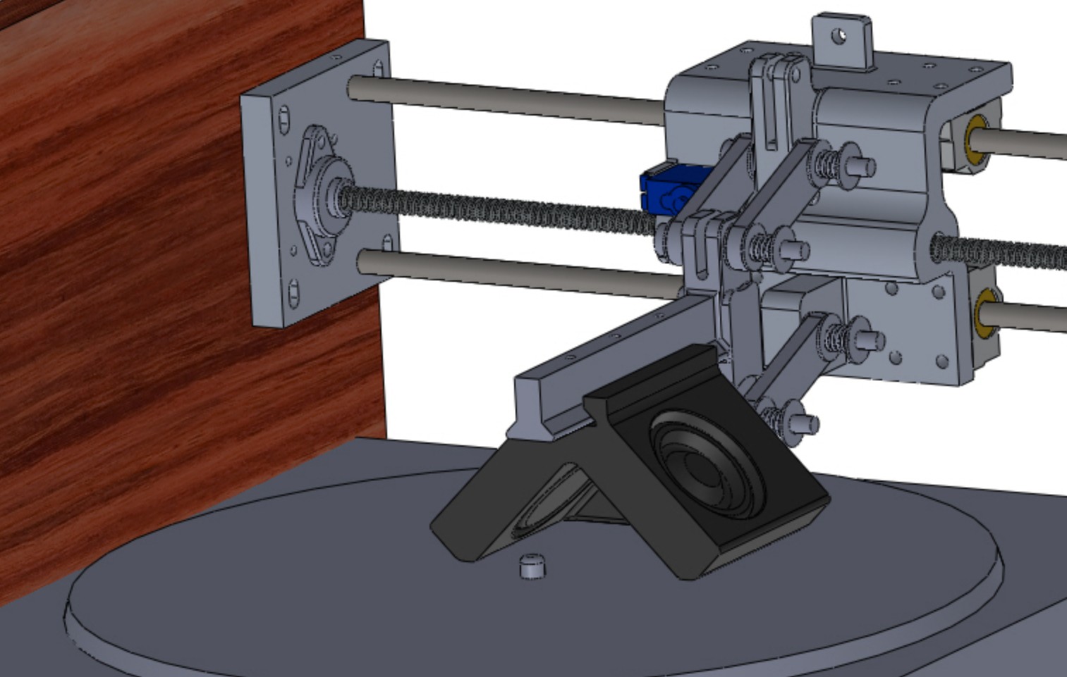
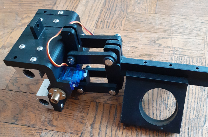
6.2) Head
6.2.1) Standard mechanical pieces
Standard pieces for the head can be purchased on the internet, here is the list:
- Worm chicago (5mm)
- Worm (M4)
- Tweeter 120 Watt minimum
- Strong glue (epoxy)
- Lacquer cutting diamond
- Spring
6.2.2) 3D pieces example
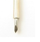
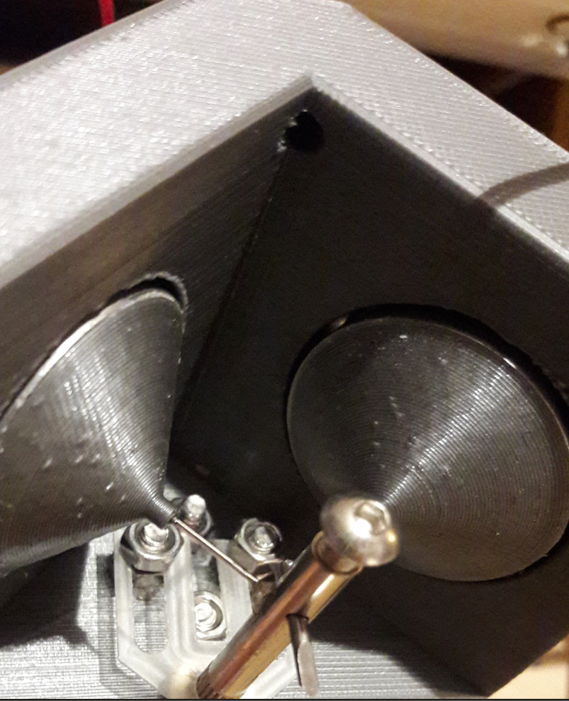
6.3) Stylus
This is the most expensive part, because we need a cutting “diamond”. It can be purchased on the internet for more than 100$. For a cost reduction, some people use Roland blades, around 5$ but it is not the same sound quality.
Diamond
Roland blade
-
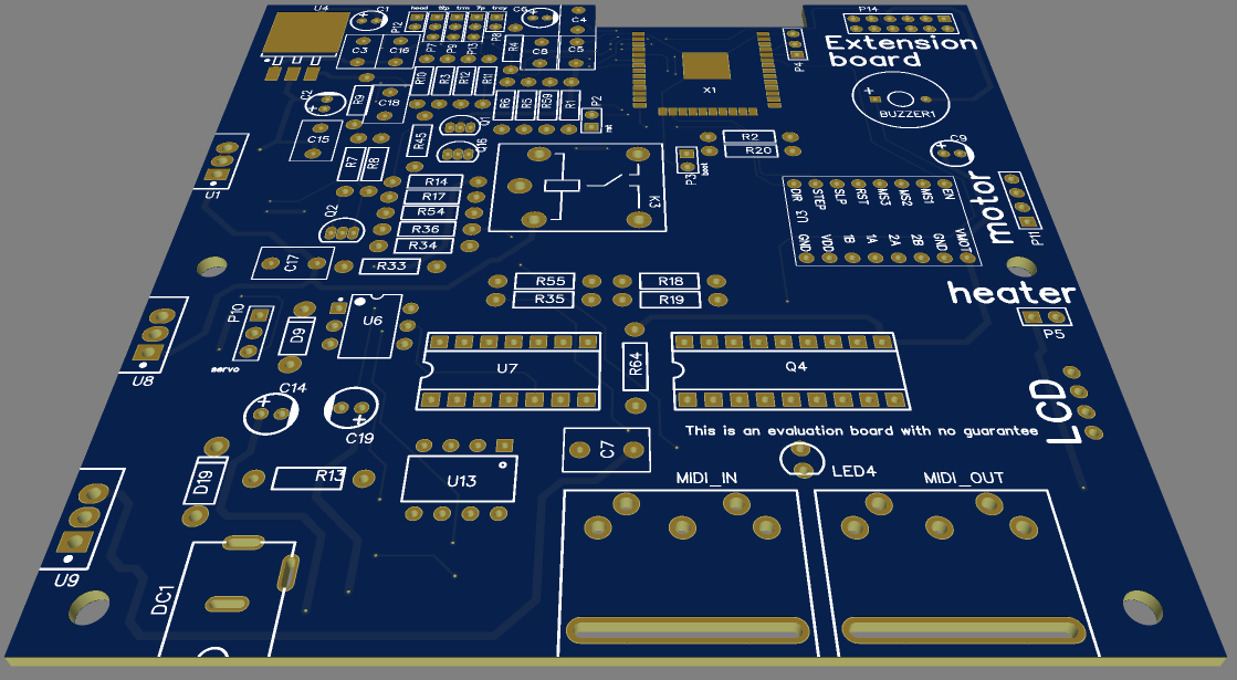
5) The PCB
08/29/2021 at 19:06 • 0 commentsAll schemas and PCB (gerber), can be downloaded on the VinyGo git project. https://github.com/Mras2an/VinyGo/tree/master/02_Hardware
The PCB does not have any particular constraint except to respect the "hardware design" proposed by Expressif to have the best radio performances. “make sure that the module is not covered by any metal shell. The antenna area of the module and the area 15 mm outside the antenna should be kept clean”.
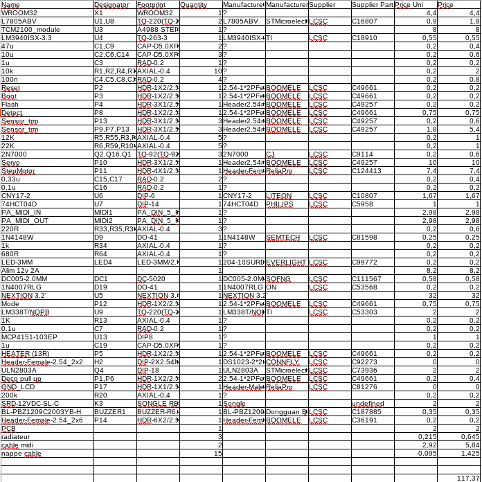
5.1) PCB components list (Price in $)
The BOM can be found here: https://github.com/Mras2an/VinyGo/tree/master/02_Hardware -
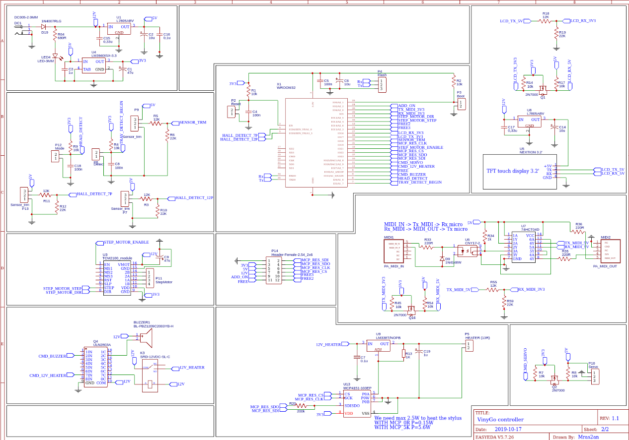
4) Electronic
08/29/2021 at 18:57 • 0 commentsAll schemas and PCB (gerber), can be downloaded on the VinyGo git project. https://github.com/Mras2an/VinyGo/tree/master/02_Hardware
4.1) Structural diagram
4.1.1) FS1.1: Power supply
Create power for all features on VinyGo Board. Input voltage 12V 5A, output voltage, +12v, +5V, +3.3V, 0V.
DC1: 12V connector
D19: Protection diode.
R64, LED4: Bleu LED,information on the powered board.
C1, C2: Polarized chemical capacitors. They perform the filtering, and allow a decoupling in case of power supply
C2, C16, C3: Plastic capacitor, serves as an anti-parasite to suppress high frequencies (it is recommended in the technical documentation).
U1: 5V regulator, it allows to regulate the input voltage 12V DC in a voltage of 5V DC. According to the manufacturer's documentation of the 78XX, a minimum input voltage of the output voltage plus Vdrop (2V) or Ve = Vs + Vdrop = 5 + 2 = 7V minimum is required for proper operation.
U4: 3.3V LDO, it allows to regulate the input voltage 5V DC in a voltage of 3.3V DC.
4.1.1.1) Calculation of a radiator
Pmax = (Tj – Ta)/RTHja = (125-25)/65 = 1,5W
Supposition for 3V3 WROOM32: 90mA, other 50mA max
Isystem = 90+50 = 140mA
Putil(3.3V) = Isystéme*(Ve-Vs) = 140*10^-3*(12-3.3) = 1,218W
Putil<Pmax.
Supposition for 5V: Servo motor 120mA, Sensors 40mA, MIDI 10mA, other 60mA
Isystem = 120+40+10+60 = 230mA
Putil(5V) = Isystéme*(Ve-Vs) = 230*10^-3*(12-5) = 1,61W
Putil>Pmax.
The utility of a radiator for regulators 3V3 is not essential at room temperature.
But we need a radiator for 5v.
4.1.2) FS1.2: LCD touch screen
Display digital information for the user and make order acquisition by the microcontroller.
Q1, R14, R14: Convertor 3.3V to 5V
R18, R19: Convertor 5V to 3.3V
U5: Nextion HMI display connects to peripheral MCU via TTL Serial (5V, TX, RX, GND) to provide event notifications that peripheral MCU can act on, the peripheral MCU can easily update progress, and status back to Nextion display utilizing simple ASCII text-based instructions.
U8: 5V regulator, it allows to regulate the input voltage 12V DC in a voltage of 5V DC. According to the manufacturer's documentation of the 78XX, a minimum input voltage of the output voltage plus Vdrop (2V) or Ve = Vs + Vdrop = 5 + 2 = 7V minimum is required for proper operation.
4.1.2.1) Calculation of a radiator
Pmax = (Tj – Ta)/RTHja = (125-25)/65 = 1,5W
Supposition for LCD 5v: 130mA max
Isystem = 130mA
Putil(5V) = Isystéme*(Ve-Vs) = 130*10^-3*(12-5) = 0,91W
Putil<Pmax.
The utility of a radiator for LCD is not essential at room temperature.
4.1.3) FS1.3: Sensors
Detection of engraving head positions.
P13, R11, R12: Connector for hall sensor to detect end of 7p vinyl.
P7, R3, R10: Connector for hall sensor to detect end of 12p vinyl.
P12, R9, C18: Connector to detect if the engraving head is up or down
P8, R4, C8: Connector to detect if the tray is on begin position.
P9, R5, R6: NOT use
4.1.4) FS1.4: MIDI
Technical standard that describes a communications protocol, digital interface, and electrical connectors that connect a wide variety of electronic musical instruments, computers, and related audio devices for playing.
Q16, R45, R54: Convertor 3.3V to 5V
R55, R59: Convertor 5V to 3.3V
MIDI1, MIDI2, Connector In and Out for MIDI.
R33, D9, U6, U7: Convertor of MIDI to Rx UART.
R35, UT: Convertor of Tx UART to MIDI.
4.1.5) FS1.5: Uc
Ensures through a programmed treatment (software) the acquisition, processing and return of information. It communicates with the motors(PWM), sensors(GPIO), LCD(UART), MIDI commands(UART), and offers inputs / outputs to add additional functionality like VinyGo sound mastering.
R1, C4, P2: Allows a reset on the wroom32.
C5, C6: Used to filter high and low frequencies.
P4: Allows programming the wroom32 via a UART.
P3: Set wroom32 to programming mode.
4.1.5.1) Definition of the inputs, outputs of the micro-controller.
4.1.5.1.1) Inputs
Boot: Set the WROOM32 to programming mode.
Reset: Allows a reset on the WROOM32.
Flash: Send binary to the wroom32 memory.
HALL_DETECT_7P: Detects end of 7p vinyl.
HALL_DETECT_12P: Detects end of 12p vinyl.
RX_MIDI_3V3: UART signal for MIDI protocol.
LCD_RX_3V3: UART signal for LCD protocol.
SENSOR_TRM: NOT use.
MCP_RES_SDO: SPI data from Digital POT.
HEAD_DETECT: Detect if the engraving head is UP or DOWN.
TRAY_DETECT_BEGIN: Detects if the tray is at the initial position.
4.1.5.1.2) Output
TX_MIDI_3V3: UART signal for MIDI protocol.
STEP_MOTOR_DIR: Select the motor direction.
STEP_MOTOR_STEP: PWM signal.
LCD_TX_3V3: UART signal for LCD protocol.
MCP_RES_CLK: SPI clock for Digital POT.
STEP_MOTOR_ENABLE: Enable step motor driver
MCP_RES_CS: SPI select for Digital POT.
MCP_RES_SDI: SPI data for Digital POT.
CMD_SERVO: PWM signal
CMD_12V_HEATER: Enable heating
CDM_BUZZER: Buzzer signal.
4.1.6) FS1.6: Heating stylus
Heat the diamond for a better cutting. Max 500mA for 5v, see diamond specification for more details.
U13, R20: SPI Digital POT
U9, R13, U13: Adjustable linear voltage regulators, capable of delivering more than 5 A at an output voltage between 1.25 and 32 V.
C7: Polarized chemical capacitors. They perform the filtering, and allow a decoupling in case of power supply
C19: Plastic capacitor, serves as an anti-parasite to suppress high frequencies (it is recommended in the technical documentation).
4.1.6.1) Calculation of a radiator
Pmax = (Tj – Ta)/RTHja = (125-25)/65 = 1,5W
Supposition for 5V heating: 500mA
Isystem = 500mA
Putil(5V) = Isystéme*(Ve-Vs) = 500*10^-3*(12-5) = 3,5W
Putil>Pmax.
We need a radiator for heating regulators.
4.1.7) FS1.7: Step motor
Move the engraving head on the X axis.
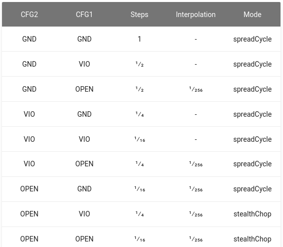
U3: Provides an integrated motor driver solution for 3D-Printing, Cameras, Scanners and other automated equipment applications. The device has an integrated micro-stepping indexer.
P11: Step motor connector.
C9: Polarized chemical capacitors. They perform the filtering, and allow a decoupling in case of power supply (it is recommended in the technical documentation).
4.1.8) FS1.8 Servo motor
Move the engraving head on the Z axis.
Q2, R7, R8 Convertor 3.3V to 5V for servo motor PWM signal.
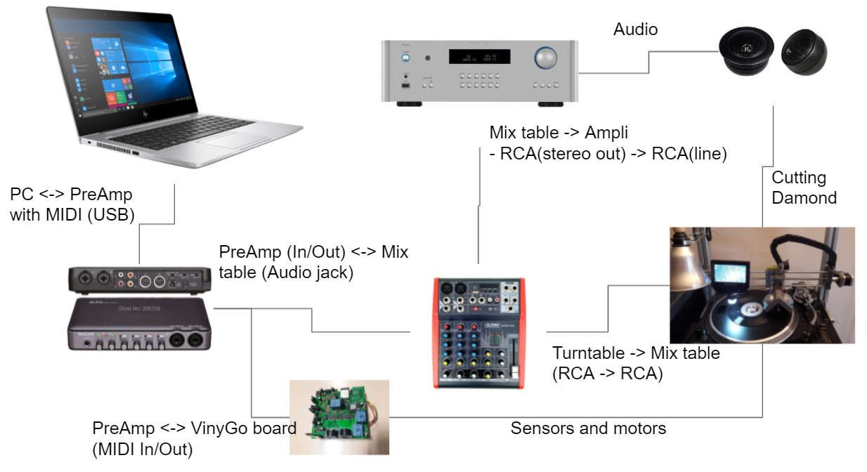
VinyGo, a stereo vinyl recorder
For artists, vinyl stores, recording studios, or music lovers


 6.2) Head

 Roland blade