Close
0%
0%

Basic Farm Robot 2021

Minimal 'no frills' development platform for farm robots

Similar projects worth following
Having been involved in the development of a number of farm robots, we decided to go back to basics and re-visit the main systems and think how they could be simplified and made more accessible to people wanting to start out building a farm robot from scratch. This is not a beginner's project and is aimed at entry level farm robot developers who need to get a quick start with advanced, highly accurate, GPS sensors.

If anybody wants to support any of our projects, check out our Amazon Wishlist here: https://www.amazon.co.uk/hz/wishlist/ls/3AW6R7V5BVU3R?ref_=wl_share

Patreon donations can be made here: patreon.com/Goat_Industries

Prerequisites for reproducing this project:

  • Good familiarly with Linux, ARM based small board computers.
  • Basic ability to code in Python and C++ and use of compilers / build systems.
  • Good level welding and fabrication skills.
  • Good knowledge of Ethernet, WIFI and TCP / IP.
  • Basic knowledge of electrics / electronics.
  • No expert knowledge required.

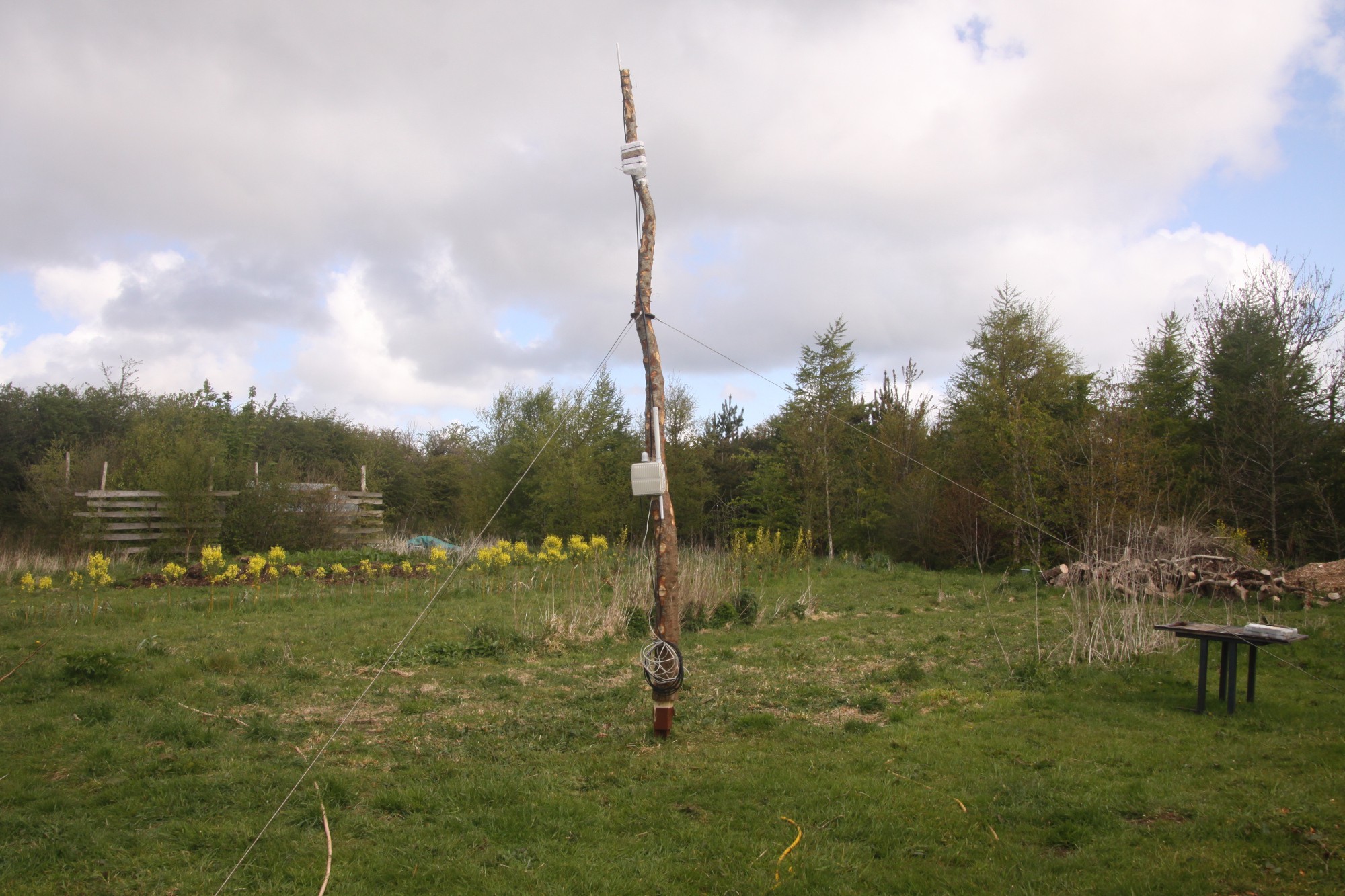
As previously mentioned, this machine is deliberately kept to the simplest design possible to enable basic autonomous navigation around a farm. There is currently only one set of sensors - advanced GPS sensors - and these obviously need a platform to work off, so the sensors and associated software are only a small part of the project. A robot developer can then add all the other sensors he might require after getting the basics in place.

As the title suggests, this project is all about providing solutions that are relatively easy and cheap to implement, but still effective enough to get excellent results. People who come to visit on site often ask "What does it actually do", thinking it must weed some crops or such like and we reply "It does absolutely nothing. It's a Do Nothing robot". This is a slight exaggeration, as it could quite happily tow an agricultural 'implement' behind it such as a mower, but essentially all it does is drive around a field autonomously.

The chapters in the instructions are as follows:
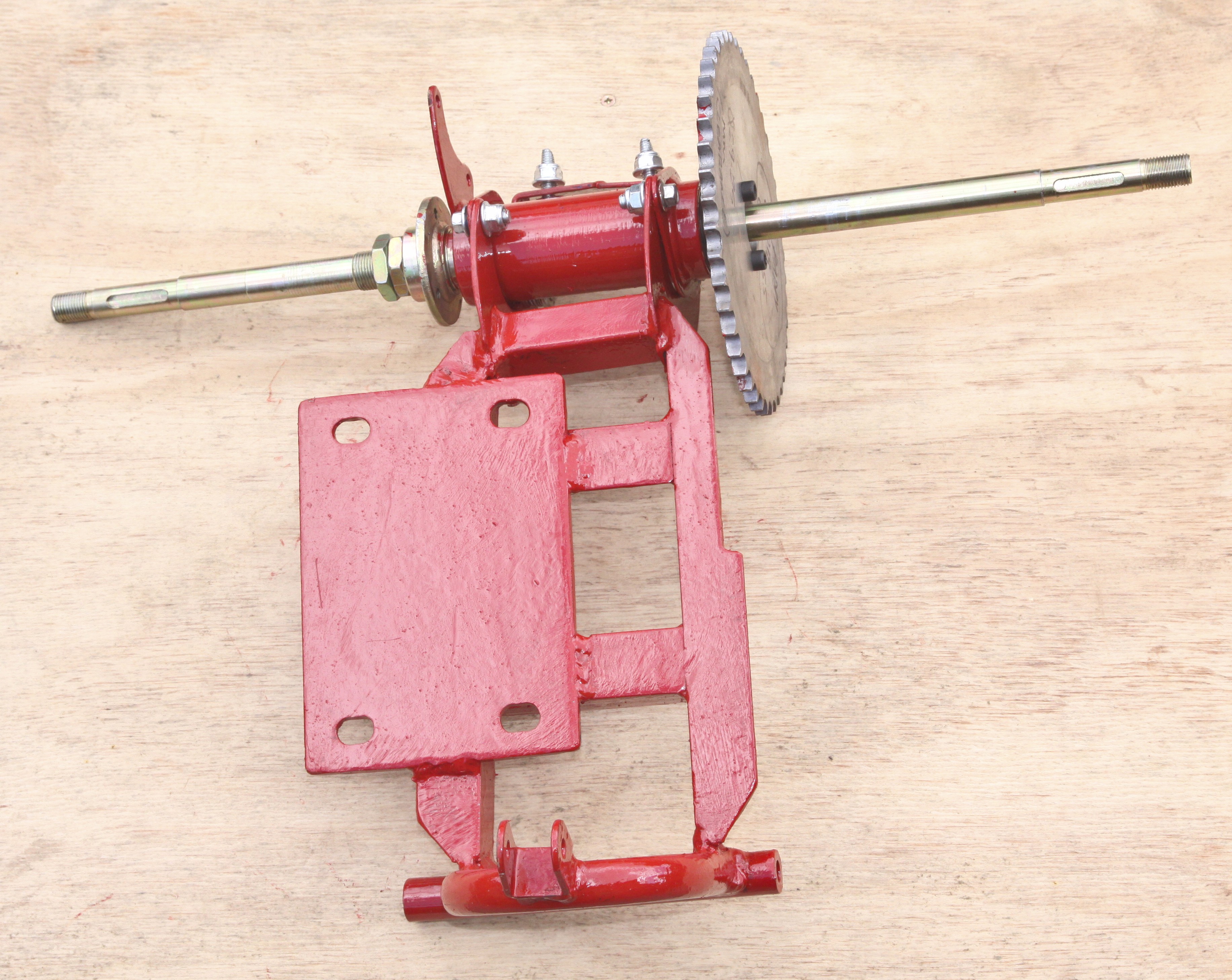
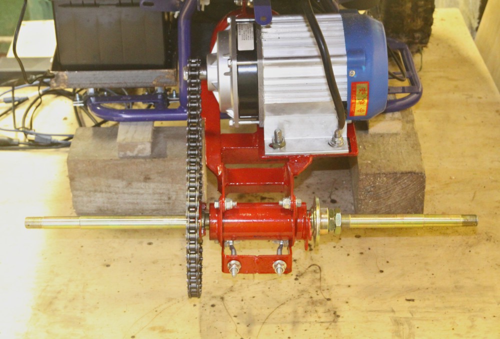
  • Mechanicals
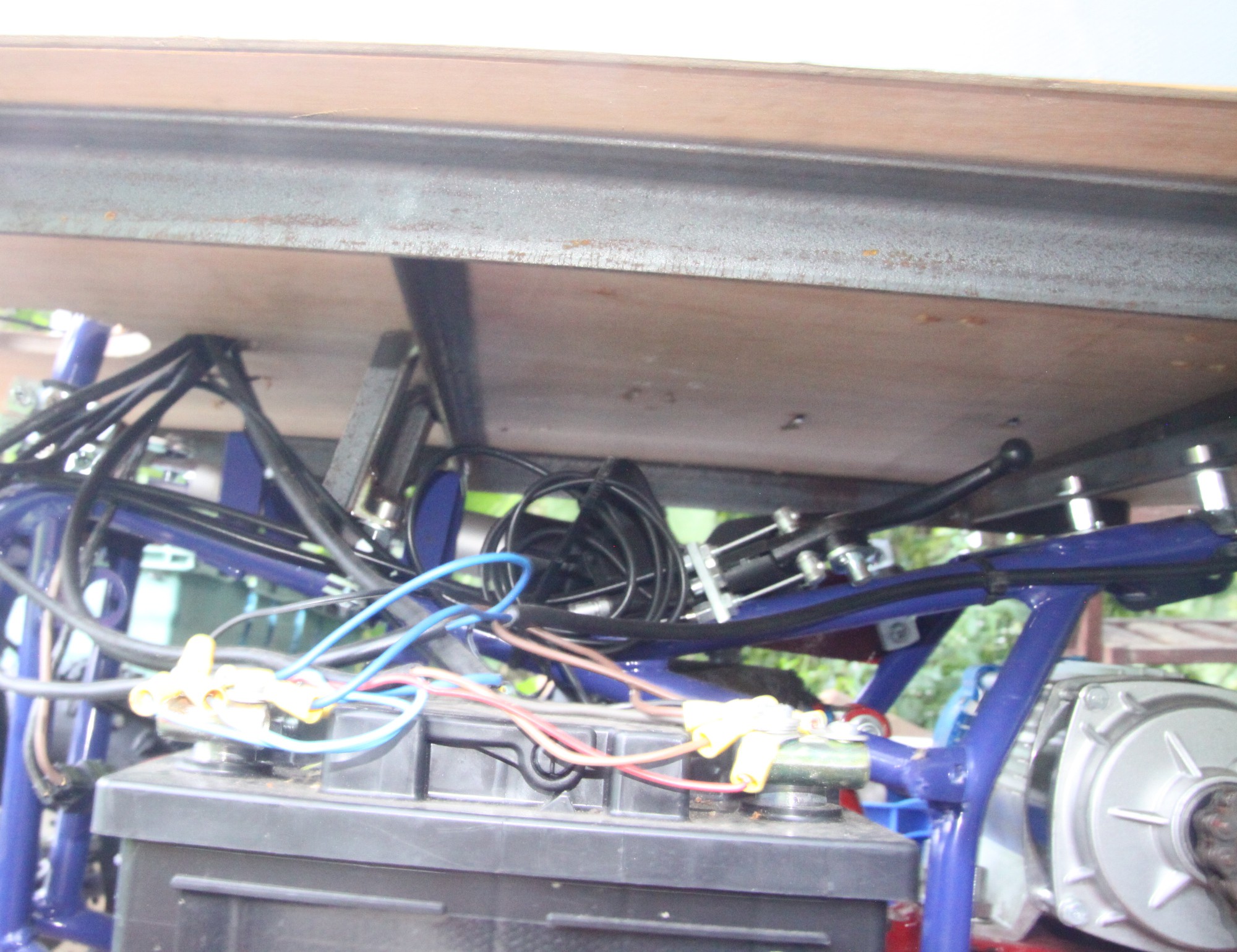
  • Electrics / Electronics
  • Control system
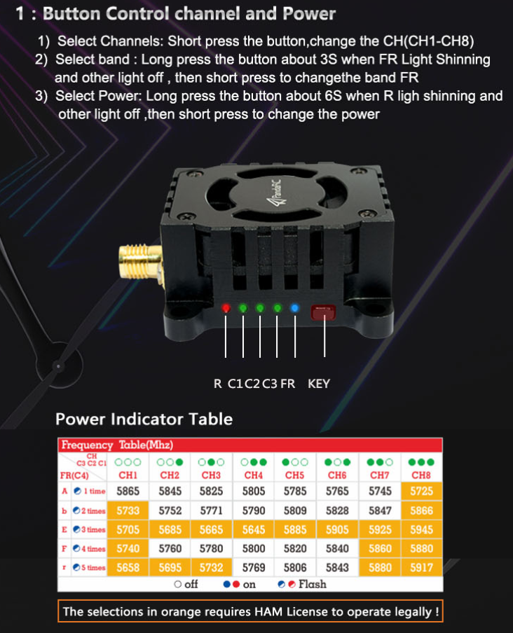
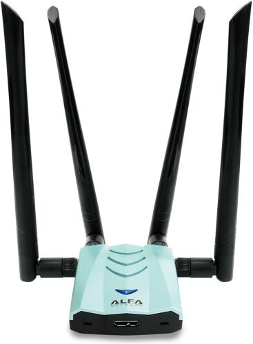
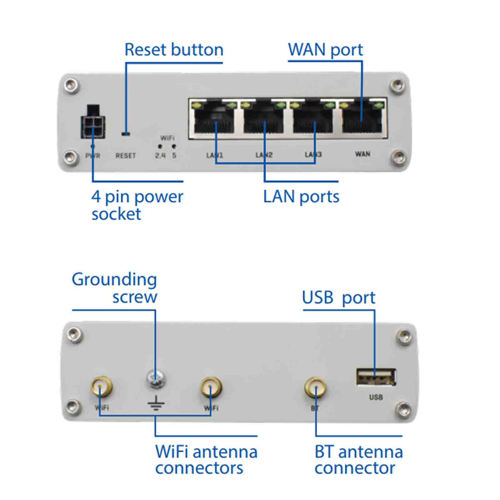
  • Radio communications
  • Sensors
  • Software

The Instructions section describes the features that WORKED and that we want to keep. The log section describes features that we experimented with and that either failed or we decided not to carry on with for whatever reason. Both successes and failures are extremely valuable in the path forwards and both deserve documenting with equal merit.

  • 1 × 'Renegade LT100E' electric 36v quad bike
  • 1 × Gimson Robotics GLA4000-S 12V DC Linear Actuator
  • 1 × Heavy Duty Stainless Steel Actuator Bracket, 10mm Pin
  • 1 × TE Connectivity, 12V dc Coil Non-Latching Relay DPDT, 30A Switching Current Flange Mount, 2 Pole
  • 1 × RUX11 Rugged Router Board (base station) for control centre and 4g internet connectivity features https://teltonika-networks.com/product/rutx11/

View all 16 components

  • all your (moving) base are belong to confusion

    lee.hughes201109/07/2021 at 14:53 0 comments

    When using the ublox f9p GPS chip, there's a lot of terminology, overloaded technobabble and when adding the documentation from ardusimple, which by it's a nature seems to based in spain, with non-native english speakers, i think you can probably tell whats going to happen...yep confusion. it takes time to get it, because the f9p has some many configuration settings and multiple ways it can be integrated and where RTCM can be piped, and processed.

    simpleRTK2B: the first multiband RTK shield based on ZED ...

    In the documentation , it covers things like .


    Base – rover configuration

    Base – multiple rovers configuration

    RTK moving base configuration

    Standalone with RTK/SSR corrections 

    So, we tried to come up without our own terminology 

    The Nest -> A non-movable GPS unit which provides RTCM correction data.

    The Dog -> The actually robot the 'moves around'.

    The Snout -> Another GPS unit on the Robot which can give us heading data.

    When we started to use this, we got our heads around the problem better and was able to visualise what we were trying to do, like an animal, that has a body and snout, and lives in a nest!! :-). 

    As the documentation starts to ramble into moving base , to a moving rovers to the moving base rover,  you can find this for your amusement here.

    https://www.ardusimple.com/question/ardusimplertk2b-rasberry-pi-base-unit-paired-with-rasberry-pi-rover-moving-base-rtcm-over-wifi-tcp/

    --------------------------

    'Hi weedinator,
    If your rover is formed by a simpleRTK2B and a simpleRTK2Blite, your rover is actually a “rover + moving base” and “rover from moving base”. Don’t mix these with your static base.
    The RTCM stream is as follows:
    – Static base sends static RTCM to “rover + moving base”
    – “rover + moving base” sends moving base RTCM to rover

    -----------------------------

    you can read more nonsense from ublox themselves.

    https://www.u-blox.com/en/docs/UBX-19009093

    in section 1.1 you can basically cause your head to spin.

    so, the whole thing with base, base station, moving base, moving base station, move base..

    so in the end, you just have to accept that it's 'all your base r belong to us, someone set us up the bomb'.

  • FPV (First Person View) Camera Rig

    Capt. Flatus O'Flaherty ☠09/01/2021 at 16:15 0 comments

    1× 5ghz First Person View send/reciver unit
    1 × Skyzone RC832-HD 48CH 5.8Ghz FPV Video Receiver with HDMI Output, Item No FPV-RX RC832HD
    1 × PandaRC - VT5804 V3 5.8G 1W Long Range Adjustable Power FPV Video Transmitter Item No FPV-VTX-VT5804V3
    1× SONY 639 700TVL 1/3-Inch CCD Video Camera (PAL) Item No FPV-CAM-639

    Receiver:

    The receiver, as above, is a Skyzone RC832-HD 48CH 5.8Ghz FPV Video Receiver with HDMI Output, Item No FPV-RX RC832HD and features a HDMI output, as well as video AV. Power input: 6-24V.

    Transmitter:

    The transmitter is PandaRC - VT5804 V3 5.8G 1W Long Range Adjustable Power FPV Video Transmitter Item No FPV-VTX-VT5804V3 input voltage range: 7V-28V with adjustable power for long range use where appropriate.

    1. Long press the button for 6 Seconds: The power indicator led flash while other indicator leds are off, then short press would change the power 25mW/200mW/400mW/800mW/1000mW.  2. Short Press one time, it will change the Channel (CH1-CH8). 3. Long press for 3 seconds and then short press, will change the FR (A-F).

    IMPORTANT: Do not turn the transmitter on before attaching the antenna, doing so will permanently damage the board!

    After testing the camera rig on various power supplies, we found it needed at least 12v and the manufacturers power supply specs are wrong.

  • GPS correction data over wifi.

    Capt. Flatus O'Flaherty ☠08/31/2021 at 21:03 0 comments

    The ardusimple board we have been using a very accurate GPS system, essential for accurate localisation (positioning) of the robot.


    The correction data is generated by the GPS base station and then this data needs to be fed to the GPS chip on the robot. The Real time correction messages (RTCM) are actually a propitiatory data format, but we don't need to decode it, we just need to be able to forward it over the network and supply it to the ardusimple board at the robot end. This data is time and latency sensitive, so the quicker you get it from your GPS base station to the robot the better....and the better GPS accuracy you will get.

    There are many ways to do this, some are easier than others, some are more expensive than others.

    Correction data can be sourced from a 4G mobile connection, however we wanted the robot to be able to function without 4G mobile connectivity.  Ardusimple gives other options, such as mountable wireless cards, using either wifi, zigbee and other exotic options. I think we chose the best solutions for out needs, wifi can be very easy to troubleshoot with tcp/ip tools, rather than a mysterious black box wireless card piggy backed on the Ardusimple board.. Again, some of the long range options are eye watering expensive too!... https://www.ardusimple.com/radio-links/

    So we decided to pipe the correction data from the base station to the robot over good old WiFi, for maximum flexibility and to be able troubleshoot easily as well!

    The excellent tutorial by TorxTecStuff was amazing. We could not of done it without you.

    We used the str2str utility to pipe the RTCM data from out base station to the robot. It worked really well. 

    You'll be able to find the configuration for this on our github, so you should be able to recreate this method if you don't want to go for the more black box piggy back cards from Ardusimple.

    We did have a few problems at first be found that we had two Serial devices connected to a single ardusimple UART pin on the robot end, a time costly mistake which was compounded by contradictory wiring diagrams from u-blox and ardusimple.. which was very very very bad, a bit like crossing the streams in ghost busters. You can read about why this problem occurred in another log and how worked around it.

  • Goodbye PI WIFI!

    Capt. Flatus O'Flaherty ☠08/31/2021 at 20:12 0 comments

    We had upgraded our WIFI base station to a RUX11 , that was giving much better results. The robot still had 3x pi's on board, all connected via wifi and using the stock internal antennas.

    The range of these antenna was actually quite surprising , but as data rates increased and the robot roamed farther from the wifi access point, we were seeing wifi drop outs and degraded data rates. Sometimes the raspberry pi's would refused to reconnect, this was resolved somewhat by given them static ip address assignments, rather them constantly asking for DHCP service on wifi reconnect.

    Even with those optimisation, sometimes the network stack would just die, and not come back. Rebooting pi's becomes a chore, and not something you want to be doing on a production robot. The internal wifi cards on pi's are not designed for realtime robot communications!!!!! 

    We also need to get greater range, we played with a few external USB wifi cards, that had high gain antennas. 

    we tried 

    https://www.alfa.com.tw/products/awus1900?variant=36473966231624

    it was kinda great? It was long range, had great performance.

    I spent a little bit of time configuring the pi to become a wireless bridge and all seemed fine.

    After testing however, on boot, sometimes the device would not be recognised, having to visit the robot, disconnect the usb and reconnect it was a bit of pain it the ass.

    The drivers seemed to be pretty low quality, sometimes even core dumping the pi.

    So a classic case of good hardware, poor software drivers that plagues many of these usb devices.

    When pumping through low latency video, it would get hot, very hot, i think that's the thing that killed it in the end. This and the fact that the networking stack on rasbian is a bit of mess, and gets messier when you start adding extra usb wireless devices. To reduce complexity i completely disabled the pi on board wifi with rfkill and in the boot configuration file, after a few days ...the wifi device came back from the grave!!! causing a few scripts i'd hardcoded with interfaces address to start mysteriously failing!! arghh!!!

     we decide to shelve this short lived USB wifi experiment and get serious.

    The solution was to add a dedicated RUTX10 router board to the robot, not only did this give us good stable wifi connectivity with the flexibility of openwrt, but able to add external high gain antenna's, and give us physical Ethernet ports too. As the pi's were now just using Ethernet to communicate and all wifi management was done by the RUTX10, the pi's were running cooler and using less power, less things connected to wifi too....i'd call that a win. Networking was starting to work reliably so we could get on with other things! 

  • ROS VS ROS 2

    Capt. Flatus O'Flaherty ☠08/31/2021 at 19:40 0 comments

    Robot operating system 1 is awesome.

    Robot operating system 2 is also awesome.

    When we started the project we were new to ros, our previous project the weedinator implemented all the network plumbing , serial communication and control systems with our own code!!!! You can see the result of our work here.

    https://hackaday.io/project/53896-weedinator-2019

    Ros has greatly simplified and standardised the communication between MCU control boards, various sensors, single board computers and all the other things that a robot needs to function in the real world. A robot is essentially a distributed message passing system and ros makes developing one a breeze.

    We first tried the latest and greatest, ROS 2, although it seemed promising, there was a lack of coherent documentation, previous forum and support posts. This is not a technical problem or criticism of ROS 2, it's just because it's so new, a victim of it's newness!!. There are many pieces of code and packages important to robots that have yet to be ported to ROS 2. This is a monumental task so don't expect it to happen over night. Yes, we know we can run ros 1 modules on ros 2, but seeing as we were just learning, that seems a bit too star trek for back then.

    We definitively think ros 2 is the future, but all the learning material and books we had all referenced ros 1 ! 

    After we got into a few dead ends with ROS 2, we switched to ROS 1, and we started to make much more faster progress, just because of the wealth of support, articles , how to's , code and prebuilt packages that can be found on the internet and in book stores!!!

    Ros 2 will surely get better as time goes on, but for now, we got what we wanted from ros 1.

    We would like to thank everyone who has contributed to ros over the years, without the hardwork the ros community has done this project would not exist. 

  • Realtime Low Latency Video

    Capt. Flatus O'Flaherty ☠08/31/2021 at 19:06 0 comments

    Getting good low latency video from the robot to the control centre is alway a bit of a condrum. using a webcam connect to a single board computer is usually the way forward. Picture Latency can cause problems when remote piloting leading to collision and crashes (real crashes not software ones!).

    We needed good high quality video so we could remotely pilot the robot in various environmental and lighting conditions while being High Definition enough to spot obstacles and hazards in our path. 

    https://www.logitech.com/en-gb/products/webcams/brio-4k-hdr-webcam.960-001106.html

    Logitech Brio Ultra HD Pro Webcam, 1080p/60fps Hyper-Fast Streaming, Wide  Adjustable Field of View, 5X Zoom, Works with Skype, WebEx, Cisco Jabber,  Zoom, Windows Hello, PC/Mac/Laptop/Chrome - Black: Amazon.co.uk: Computers  & AccessoriesAfter playing we a few streaming solutions, from ffmpeg to RTMP servers, we were seeing latency of 5-10 seconds, after tuning codecs parameters and network/video buffers we could get it lower, but just felt it wasn't real time enough for our robot.  We decided to have a go with NDI for a laugh.

    NDI is proprietary codec for HD, low latency streaming over LAN's , however with the right networking equipment it will work over WIFI too ( with a few hacks ) :-).

    We built, configured and compiled most of the software from scratch to get a NDI stack running on raspberry pi... it was a long arduous task until we found https://dicaffeine.com/about


    This entire distribution turns your pi into dedicated NDI encoder device. You have lots of options for resolution and frame rate.

    We terminated the NDI stream to a ubuntu machine running Open Broadcast Studio, which can be configured to receive NDI streams.

    After we fixed the network problems with increase data rates of the NDI codec , detailed here https://hackaday.io/project/181449-basic-farm-robot-2021/log/197307-multitech-woes , we got good results with low latency (really insanely quick) HD video from the robot. Error recovery was also swift in case of degraded a wifi connection. Impressive.

    You can see all this in action in our youtube video here 

    NDI OBS in action

    However, as with all things, the real world calls, we found the most of the wifi link bandwidth was saturated with NDI packets, we could of added another 2.4ghz/5ghz router to the robot and another access point on different dedicated wifi channels ,  but this would just of added extra expense and complexity to the robot and the control center. Perfect design is not what you can add to something, but when you cannot take anything more away.


    In the end we decided to got for a dedicated 5ghz analogue video connection , they usually have better range and better error recovery, where a 'snowly' picture, is better for the human operator than a complete break in picture feed that many digital encoding systems suffer from.

    You can read more about adventures with FPV camera in another log.!

    One last thing to mention is the https://dicaffeine.com/about really is great software for your low latency video projects, the free version will run for 30 mins before you need to restart it , it's certainly worth every penny if you plan to used NDI steaming on your network!!!! 

  • Multitech woes

    Capt. Flatus O'Flaherty ☠08/31/2021 at 17:52 0 comments

    Wifi Network woes.

    Our first task was to get a stable wifi connection to the robot. The only thing we has available that was IP68 rated for out door used was a multitech MTCDTIP-LEU1 https://www.multitech.com/models/99999199LF wifi/lorawan/4g combined access point/gateway. It was quite flexible as it had power over Ethernet, so we could mount anywhere we could run a Ethernet cable.

    MTCDTIP-LEU1 pic

    This seemed like a good choice , as we could mount it in the central field where the robot would be tested, making our wifi transmission distance optimal. We made a make shift 'mast' and mounted the multitech to it.


    Our initial tests were good, we go good 2.4ghz wifi connectivity to the raspberry pi's on the robot platform, even *without* external antennas on the robot. We were also using the multi tech to provide us with 4g internet access. Things were looking good!

    As we started to run higher data rates, especially real time video , although the wifi chip could sustain those rates with ease, the CPU was being pegged at 100%, causing increased latency, data flow drop outs and constant wifi re-transmits and disconnections...all in all not good for robot communuications.

    It's poor ARM9 processor at 400 Mhz could not keep up with the data we were shunting through it, this was made worse as we were routing on main internet 4g wan through it too. Apparently new multitechs use much beefier cpu's! :-) .

    We decided to ditch the old tech in favour of  RUX industrial router boards and relegated the multitech the storage shelf once again :-(. 

    We didn't go with upgraded mulitechs because they use a yocto based linux distribution and although you had ssh access to the device for configuration/ diagnostics, there was a distinct lack of packages and configuration options. We needed to do some special ethernet/wifi bridging, multicast proxy and dns configurations. The  RUX are thankfully openwrt based, so we knew we could have the flexibility of openwrt itself, great extention packages and great business quality support on top. 

    The motto of this log is, even though something looks cool and may have the features you need, it may not be cut out for robotic communication, which needs low latency, high data rates and bullet proof reliability that are essential for remote robot control and telemetry tasks.

View all 7 project logs

  • 1
    Mechanicals

    In previous projects we spent a lot of time designing and building the mechanical systems and we really wanted to short cut all the hard work by using a ready made system that could be bought reasonably cheaply 'off the shelf'. We looked at mobility scooters and ride on lawn mowers, but the electric quad bikes were super cheap ($800) and the build quality looked ok so we took the plunge and bought one brand new. After  testing the machine on rough ground, we found that the standard motor did not have enough torque to be very useful, so had to throw it away and replace the whole drive train and motor controller with another, bigger, motor which had an extra in built gearbox to bump up the torque. Other than this, the mechanical build was quite straight forwards, with a series of small modifications such as a variety of sub frames and a mechanism for picking up the steering angle.

    One of the key mechanical components was the linear actuator for the steering. The Gimson Robotics actuator detailed in the components section is capable of delivering a staggering 450 kg of force, which is more than enough to push / pull the steering, even at when mounted close to the vertical axis of the steering column.


    This strange looking frame goes at the very front of the robot and performs two important functions. One is to mount a load of the sensors and antennae for the control system, and the other to mount an everyday 10K potentiometer to measure the steering angle. The steering angle is NOT measured by bolting the pot directly onto the top of the steering column , but via a gearing reduction timing belt to make better use of the pot's range and hence better resolution. This also has the benefit of hiding the pot deep within the frame work, well out of harms way. Video 3:

    All the photos and drawings needed to build the sub frame and bracket are given in this step, below. The important thing is to present the potentiometer assembly exactly parallel to the steering column or else the whole thing will fail and the belt might also come off the timing cogs. To prevent play, or backlash, the belt needs to be fairly tight, so the welding needs to be strong. The belt also needs some adjustment and this is enabled by the series of parallel holes drilled in the angle as seen in the photo above. Slots would also be a good option if a milling machine is available.

    The pot range and resolution was tested by using the Arduino Uno code below and we managed to get 340 units across the whole steering range, which is thought to be more than adequate. This could be further improved by using a gear ratio of 1:4 instead of 1:2.

    Code for testing the potentiometer:

    int sensorPin = A0;
    int ledPin = 13;
    int sensorValue = 0;
    
    void setup() 
    {
      Serial.begin(9600);
      pinMode(ledPin, OUTPUT);
    }
    
    void loop() 
    {
      sensorValue = analogRead(sensorPin);
      Serial.print("Pot value (0 to 1024):  ");
      Serial.println(sensorValue);
      digitalWrite(ledPin, HIGH);
      delay(250);
      digitalWrite(ledPin, LOW);
      delay(250);
    }


    As previously mentioned, the original motor on the quad bike was no good, so we took a bit of a risk on Ali Express and bought the best looking motor than could be found that looked about the right size to fit on the bike. When it arrived we knew instantly that it was going to cure the torque problem, but fitting it into the space available might be a problem. In the event, the whole rear swing arm had to be disassembled with a hack saw and welded back together to accommodate the bigger motor.

    The motor chosen for the upgrade was a 3 phase 48 V DC motor with a 5:1 planetary gearbox that could be slotted into the robot without too much modification of the rear suspension sub frame. It's always a big risk buying motors from China and when it arrived the aluminum mountings were bent out of shape like it had fallen off a conveyor belt somewhere.

    Fortunately, all went well as the mountings just bent back into shape once it was bolted onto the steel subframe. Other parts required were a 3 phase sine wave controller and some gear sprockets:

    The sprocket sizes were dictated by the absolute minimum size that could be mounted on the motor, which turned out to be 8 teeth in size and the maximum on the wheel shaft without causing ground clearance problems, 48 teeth. The chain is a standard 1/2" pitch. The large sprocket was taken to a machine shop to have the center hole widened slightly and the small sprocket was ground and filed by hand to get it to fit the motor shaft.

    The rear suspension subframe was then removed:

    This subframe was then completely rebuilt, recycling the top and bottom bearing systems:

    Then slotted back into the main frame with the new motor. Since the mountings are slotted, there is plenty of opportunity to adjust the motor position so that it is perfectly aligned with the main sprocket. This was done by slowly running the motor and watching / listening for errors.

    At this stage the motor speed looked good - no where near as fast as the previous model. It was, however running in reverse so the outer, thick, feed wires to the motor had to be swapped around and the motor re-tuned with the two green tuning wires joined together. The motor actually came with some bask instructions and wiring diagram, which was quite useful. Now the motor could be run at full speed in forwards mode. A nice feature is that reverse is engaged digitally with a switch on one of the controller connectors rather than having to use expensive MOSFETS or heavy solenoid relays as with the old 2 phase motor.

    Lastly the new motor was tested over rough ground towing a petrol lawn mower. As can be seen, it worked perfectly and did not get at all stuck like before:


    The last part in the mechanical section is just how the top coffin shaped box is fitted onto the quad bike. We used some plumbing pipe fittings that have rubber linings inbuilt:

    ... which fastened onto the cylindrical bike frame. Use enough of them and a nice strong sub-frame can be produced.

    The image above shows the top box sub-frame (unpainted 25 mm angle). The top box itself is made of plywood and is designed to provide some protection from rain and bird poo whilst providing maximum access to the electrical / electronic components inside.

  • 2
    Electrical / Electronics

    To keep the project as simple and reproducible as possible, we tried to limit ourselves to off the shelf products as much as possible. We only used one custom built PCB to control the heavy solenoid relays for operating the steering actuator. Other than that, there is a potentiometer for sensing the steering angle and a pair of joysticks for manual control of the robot and the camera gimbal. There are a number of Raspberry Pi 4's in the project - 2 in the control room and 3 on the robot itself and one Arduino Mega on the robot. At one stage we had Intel tracking cameras on a Jetson Xavier, but removed that whole set of components due to a number of fairly nasty problems. Please refer to the logs for more info.

    The first part of the robot that we'd want to get working is the motor itself. For safety, the robot should be chocked up so that it's wheels are off the ground before making any connections to the battery power.

    The motor control box can seem quite intimidating on first glance with a multitude of coloured connections. Many of them are to enable stop lights, indicators, alarms, horn etc as the controller is a generic device designed to cover 'on the road' usage. For our robot, most of the connections are not used and we can concentrate on the throttle and main wires such as the feeds to the motor and input from the battery. Normally, the control box comes with instructions, which are normally slightly wrong ! The throttle connector requires 3 connections, one to +5v, one to ground and one to signal, which will between about 2 and 4.5 volts and it's vitally important to get these connects done properly. Since the motor is 3 phase, there will be 3 heavy cables of different colours for the motor. There should be one heavy red cable for the 36 / 48 v input from the battery and one heavy ground cable. There will be one lighter weight red cable to be connected to the on off switch which then goes to the 36 / 48 v battery supply. Lastly, there are two 'intelligence' wires to connect together during initial power up so that the controller can detect the different phases of the motor and these can be dis-connected after the motor works properly. Our controller also had a forward and reverse connector. To take up the least amount of space possible, we mounted this box in an upright position within the main top box. For a development robot, non of the electric / electronics components should be buried or hidden underneath fixed panels - everything needs to be easily accessible.

    The steering control board PCB enables a low current, low voltage Arduino Mega to control a high current, medium voltage set of solenoids which need to have both a forward and reverse capability.

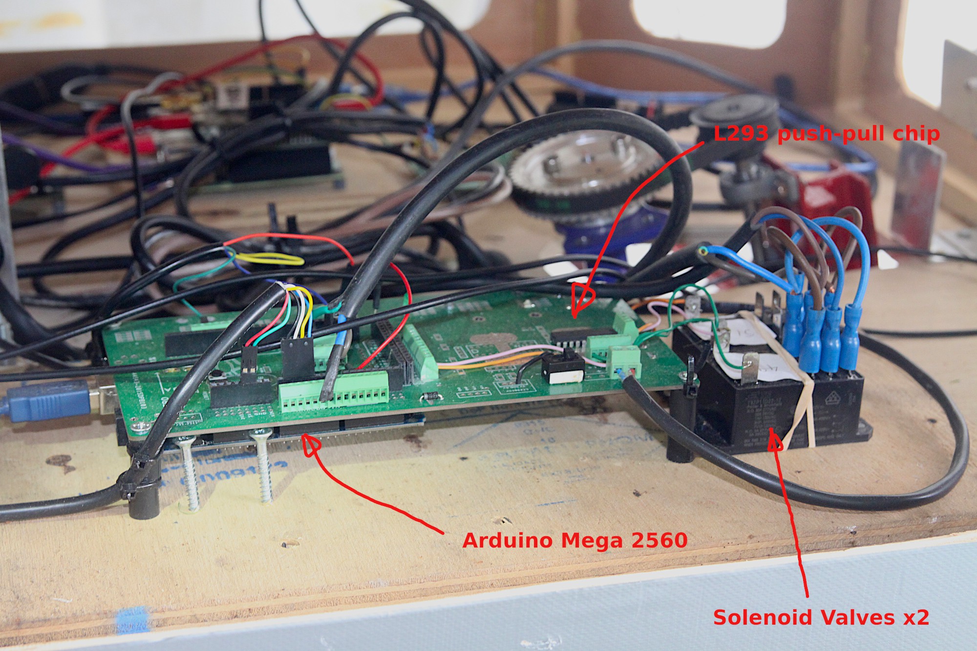
    The L293 chip, shown above, is used to step up the current and voltage for the solenoid valves, shown below.

    The valves need to be wired in such a way as to allow forward and reverse, so one valve does this function and the other does the on / off, using the circuit below:

    'High Amps' means 12v supply direct from the auxiliary 12 volt battery. '49' is the digital pin on the Mega that swaps forwards and reverse and '51' is for on / off. Below is a snippet  of the code on the Mega that controls the solenoids:

        if ((steerControlVal > 300)&&(steerControlVal < 750)) // Deadzone is set to between 300 and 750.
        {
          digitalWrite(49, LOW);
          delay(50);
          digitalWrite(51, LOW);    // Stop the actuator
        }
    
        if (steerControlVal > 750)
        {
          digitalWrite(49, HIGH);    // Turn right
          delay(50);
          digitalWrite(51, HIGH);    // Move the actuator
        }
    
        if (steerControlVal < 300)
        {
          digitalWrite(49, LOW);     // Turn left
          delay(50);
          digitalWrite(51, HIGH);    // Move the actuator
        }

     The full code for the Mega is located at: https://github.com/paddygoat/Quad-ROS-Bot-MCUs and apart from the steering, contains other code for the throttle, blinking some LEDs and a ROS node. The ROS nodes will be talked about in the 'Software' section of the instructions and we've taken great pride in simplifying the nodes in the system so that they are easy to understand and use.

  • 3
    Control System

    The robot has a distributed brain composed of different MCUs and SBCs (micro-controllers and small board computers) which need to be able to communicate with each other at high speed and with low latency. In a previous robot, we designed the internal comms system from scratch and had it running on the I2C bus of the different components, but this time we thought we'd explore using a purpose built system called ROS (Robot Operating System). One thing that ROS is not is an operating system, which is a bit strange and miss-leading. An operating system is something like Windows or Linux or IOS and ROS is more like a data communication system.

    When we started looking at ROS, there were a number of good tutorials for getting started with Arduinos, which were very useful. There are also a huge number of libraries for doing different functions and these seem to be heavily mechanical platform orientated so if we did not actually own a Turtlebot, they seemed to be largely irrelevant. We decided very early on to start writing our own nodes for ROS is Python and in retrospect, this was undoubtedly the easiest and most effective way forwards.

    Python is a interpreted language so it does not normally need manual compiling but when using a Python node in ROS, it needs to be plumbed into a complete entity using a build system called 'Catkin'. Here is an example of a typical build procedure:

    https://github.com/ros-agriculture/ublox_f9p.git
    source /opt/ros/melodic/setup.bash
    cd ~/catkin_ws/src/
    git clone https://github.com/ros-agriculture/ublox_f9p.git
    cd ublox_f9p/
    git checkout `git tag | sort -V | grep -P "^2.\d+\.\d+" | tail -1`
    cd ..
    catkin_init_workspace
    cd ..
    catkin_make clean
    catkin_make -DCATKIN_ENABLE_TESTING=False -DCMAKE_BUILD_TYPE=Release
    catkin_make install

    A re-occurring theme in ROS is the need to specify the source ie

    source /opt/ros/melodic/setup.bash

    ..... but this is all covered in the ROS tutorials, so beyond the scope of these instructions.

    To add a new python node, the Catkin build system must be activated, but once the node is in place, it can be edited at will. The best way to start is to get Arduinos blinking from a Linux PC and then work up to adding a python node. Use one of our Python nodes as a template! eg. https://github.com/paddygoat/joystick/blob/main/joystick.py ... which is a very simple but effective example.

    The key to building a ROS communications system is experimentation. Start with a simple set up and then add nodes to it. The Python scripts need to be located in the correct folder for Catkin to incorporate them eg

    ~/catkin_ws/src/

    ..... and have fun!

View all 3 instructions

Enjoy this project?

Share

Discussions

Kenstruct wrote 09/25/2021 at 14:16 point

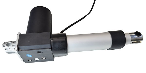
Superb project, I like the choice of chassis a lot. May I ask what length of stroke does the linear actuator have and would you change anything about it?
Thanks

  Are you sure? yes | no

Capt. Flatus O'Flaherty ☠ wrote 09/26/2021 at 13:59 point

Hello Ken, thanks for your comment. We're just doing tests on the machine today and the stroke on the steering actuator is 100 mm. It's perfect really, as a longer stroke would mean the mechanism would stick out too much on the side and interfere with other parts of the machine.

  Are you sure? yes | no

Similar Projects

Does this project spark your interest?

Become a member to follow this project and never miss any updates