 Giovanni N. Mastronardo
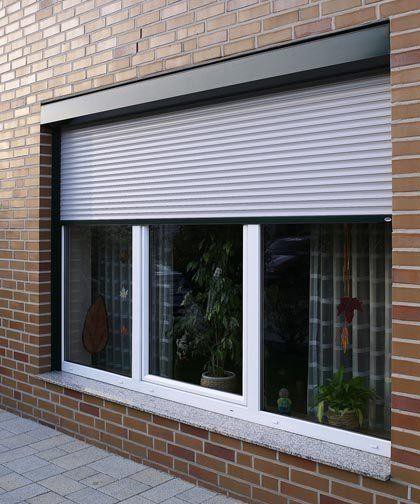
This project was designed to be used with a rolling door garage door already equipped with a motor with key switch but without a remote control.
But it is also a complete solution for those wishing to install a motor to their rolling door for the first time. It does not necessarily have to be a door for garage but also for a shop, deposit or a commercial business in general or anywhere else where there is a rolling door that you want to remotly control.
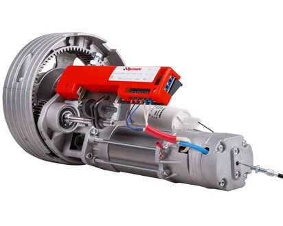
The use can also be extended for other types of doors as long as the motor than controls them is equipped with 3 wires: one for the common(neutral) and two wires(phase) for opening and closing movement respectively and that it is also equipped with limit switches.Normally these specialized motors are equipped with limit switches but it is always better to check.

HARDWARE OVERVIEW
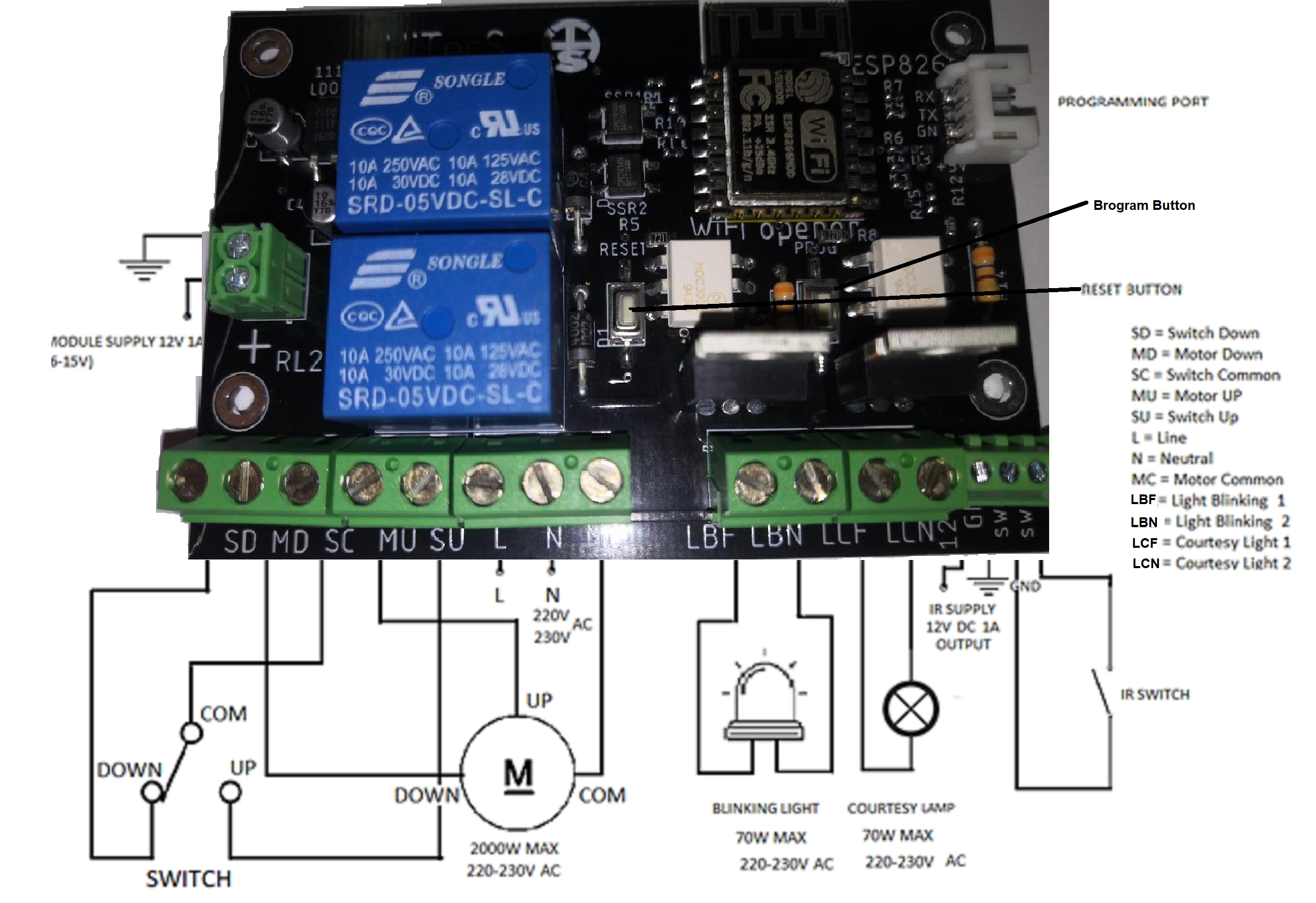
The PCB manage an AC electric motor equipped with two windings.
A winding to make the door go up and a winding to make the door go down.
Therefore there are three wires,a phase to go up, a phase to go down and
the common which corresponds to the neutral.
Can be connected any motor up to 240V AC, 2Kw.
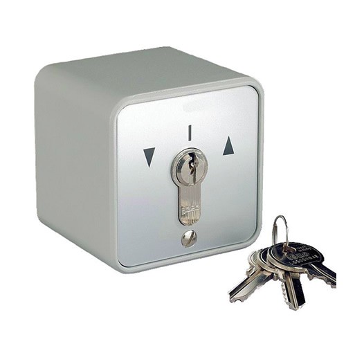
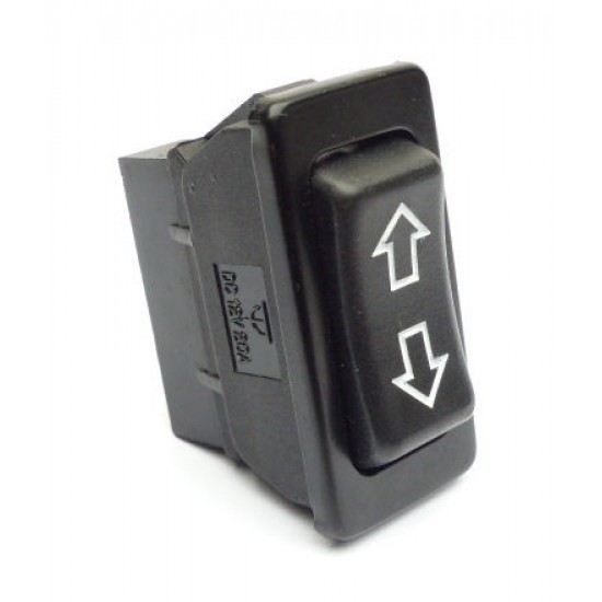
A two position switch with the neutral mechanic in the center position ,
or even a switch with the key, can be connected to the PCB.
In the rest position the common is in neutral position between
UP and Down.
The circuit has been designed in such a way that there can be no conflict if the door is inadvertently
opened or closed while holdingthe switch or the key towards one of the two position UP or DOWN.
If this is not the case, the motor could be damaged.
Going further in the description, to LB1 -LB2 a blinking lamp can be connected.
The lamp may already has the blinking circuit incorporated in it or we can let the
firmware take care of the blinking by selecting in the Android
application.

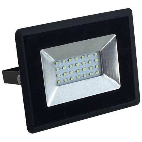
To LC1 - LC2 a lamp can be applied to illuminate the environment surrounding the door and can be operated by the Android Application. Also LED lamps can be used.
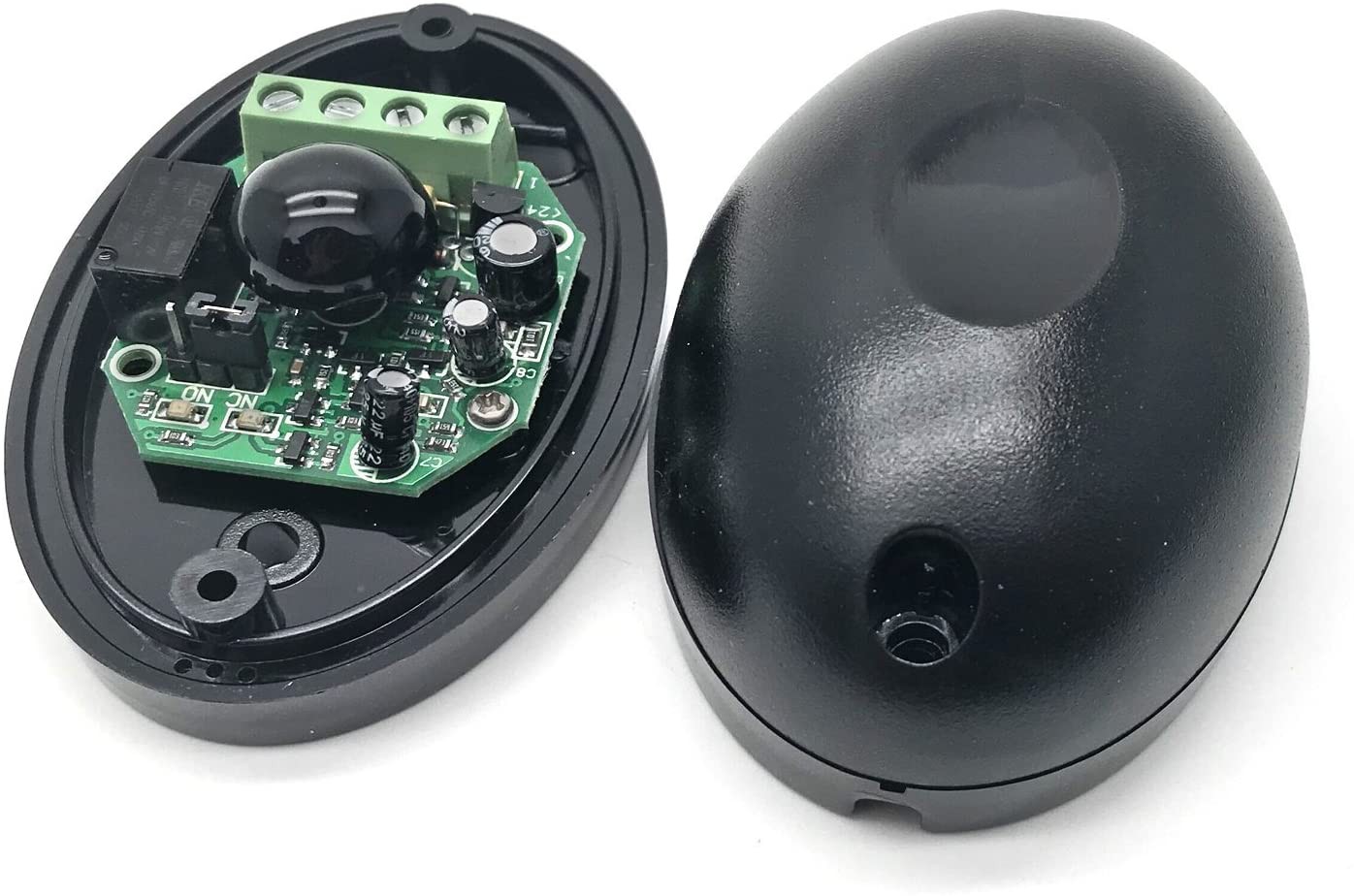
The last 4 pins connector on the right is used to connect an IR switch that must be powered at 12V.
The IR switch is used to stop the door if there is an obstacle (car o person) in the door movement area.
When the IR sensor detects the presence of an obstacle, it short-circuits pins sw1 and sw2, this is
detected by the PCB and the door opens automatically, avoiding damages to things or people.
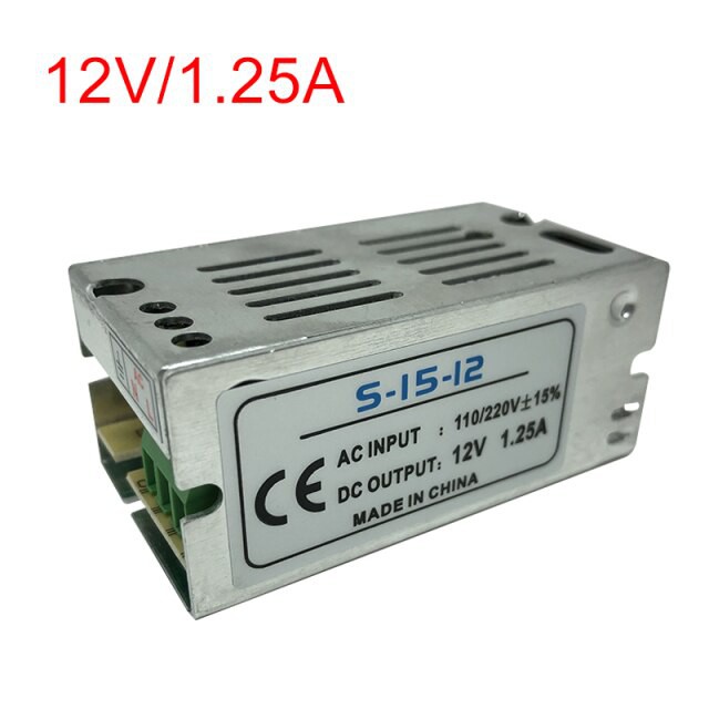
On the left side there is power supply connector. You can use any 12V 1A( or higher) power supply.
It is used to power the PCB and to power the IR sensor.
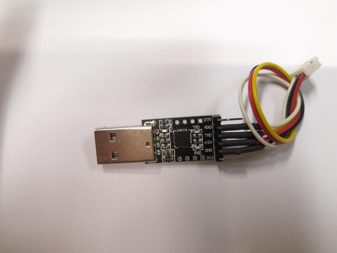
At the top right there's the connector for programming the ESP using an FTDI USB with appropriate connector.
About in the central part of the board there are the RESET and PROGRAMMING buttons.
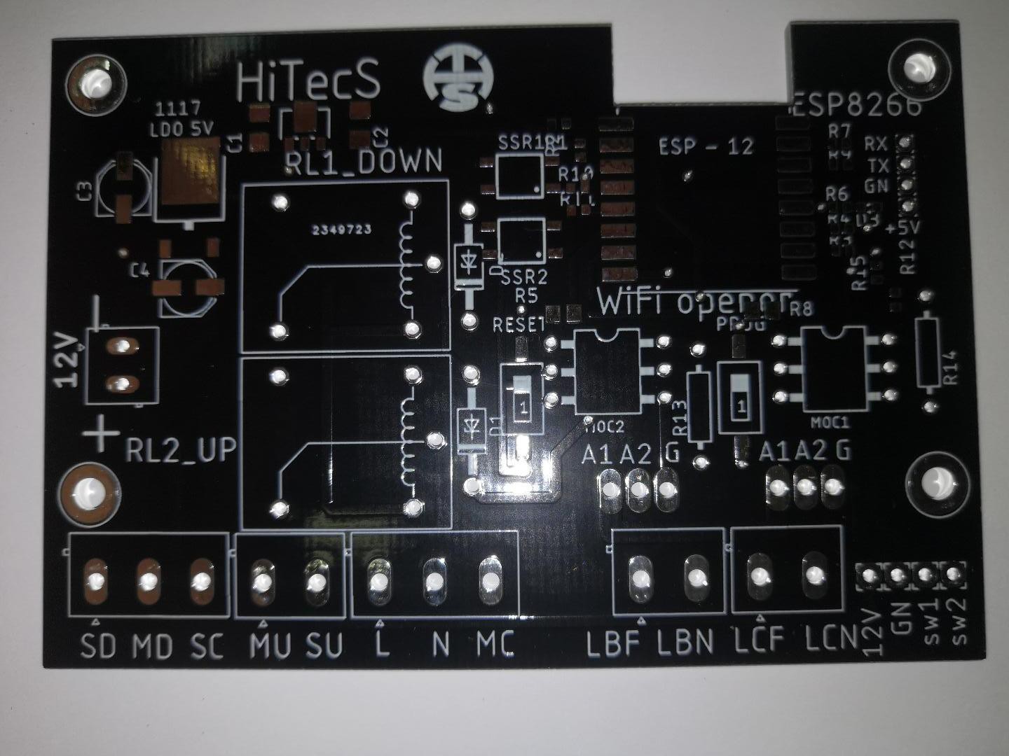
An IP WI-FI cam as ESP32 WI-FI CAM can be added and managed with the Android App.
ANDROID APPLICATION OVERVIEW
Let's take a look at the Android Application now.
This is the main screen of the application. The buttons to open the door(UP) and...
Read more »
 mbsg99
 Jeroen
 Mrinnovative
 Romeo hackster