 NotBlackMagic
Motor Encoder Tuning
As mentioned in the previous project log, the motor encoders was tuned before gluing them in place. The first part of the tuning consists on setting the reflective sensors LED drive current, by changing the LED drive resistor, and the phototransistor output resistor, which sets the sensibility. The values used are 330 Ohm for the LED drive resistor, a drive current of 6mA, and 47 kOhm for the phototransistor resistor. These give a good output swing when the leaf passes in-front of the sensor, around 250mV, while keeping the current consumption relatively low.
Next the voltage comparator threshold voltage is set to about the middle of the reflective sensor output swing, which is 2.75V. All these signals are shown in the figure bellow, in green the output of the reflective sensor, in blue the threshold voltage and in red the output of the comparator. The latter one had to be filtered by adding a 10nF capacitor to the output to remove false triggers/pulses caused by noise in the reflective sensor output. This is why it has a slow rise time and a high voltage level bellow 3.3V.
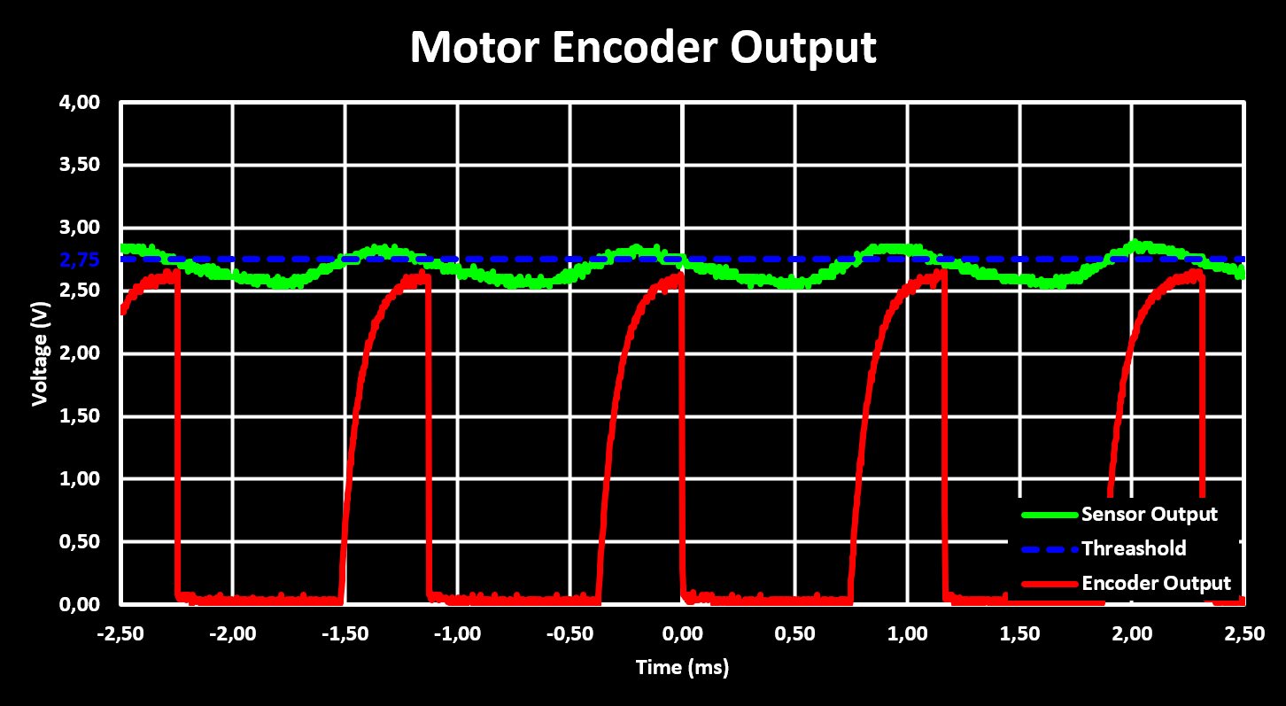
The tuned motor encoder was then glued in place, the figure above is from the final assembly already, in more then one robot chassis and it always gave a reliable output confirming that with the used resistor values the motor encoder is reliable.
Motor Drive Characterization
With the motor encoders working, glued in place and the Motor Drive PCB added on top and soldered on it was time to test the motor drive. The motors are driven with two H-Bridges in a single IC, the STSPIN240. The motor RPM is controlled by using PWM signals to drive the H-Bridge. Bellow is a figure showing the voltage and current at one of the motors terminals. The current is obtained from the INA180 connected to the current sense resistor on the motor output of the STSPIN240.
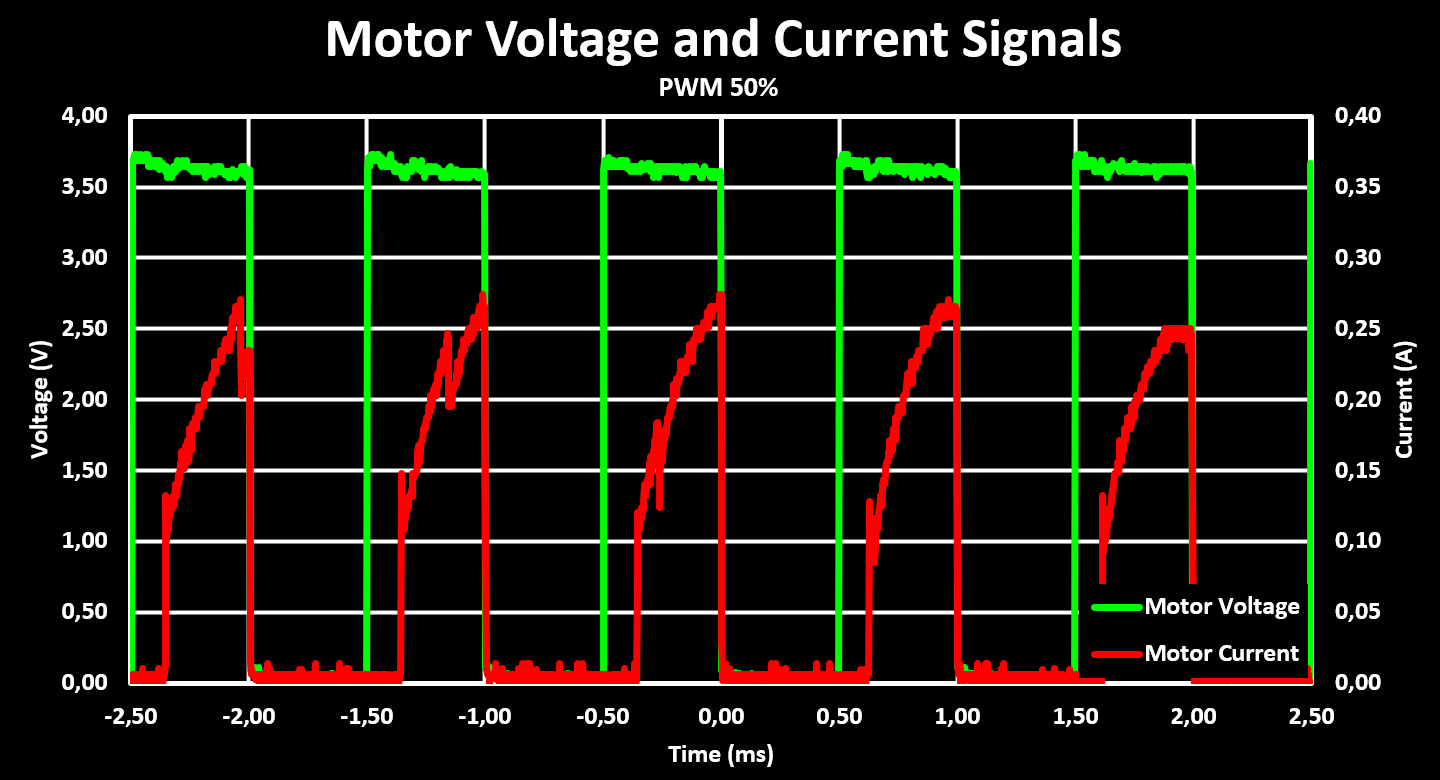
The figure shows that there is a slight voltage drop when the current increases, this can maybe be mitigated with higher capacitor values to bridge the current draw spikes but the drop is not large and so not considered a concern.
Finally, with both the motor drive and encoders working it is possible to characterize the motor RPM vs PWM duty cycle. With that and using the gear ratio and wheel diameter, the expected robot drive speed with different PWM duty cycles values and supply voltages, battery voltage levels, is obtained. This is shown in the figure bellow.
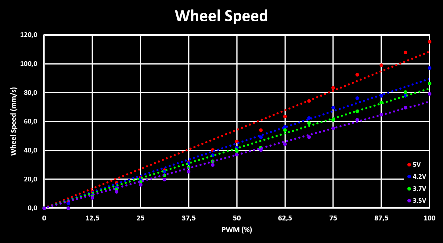
This figure shows that the maximum expected drive speed of the robot is around 90 mm/s with a full battery (4.2V) and decreases to around 75mm/s when the battery gets empty (3.5V). This means that the robot firmware will have a software limited maximum drive speed of 70mm/s so that the limited maximum drive speed can always reached, with any battery voltage.
The next step is to characterize the reflective collision sensors.
A more detailed description of the tuning of the motor encoder as well as some additional results of the motor drive are available on the Website.
Updates and progress on this project, and other projects, are published on Twitter.
Discussions
Become a Hackaday.io Member
Create an account to leave a comment. Already have an account? Log In.