Michael Gardi
-
The InSide Story
11/16/2021 at 02:45 • 4 commentsThe walnut sides of the Sol-20 are beautiful and help to set it apart from all of the other computers of the era. I really wanted to do them justice in my reproduction. I also saw the fabrication of the sides as an opportunity to advance my woodworking skills.
A couple of years ago I was thinking about building my own CNC router. At that time the The Mostly Printed CNC (MPCNC) was a popular choice. At the same time a friend told me about the Kwartzlab makerspace so I took a tour on one of their Tuesday Open Nights. I saw their massive Mach3 driven CNC router with a 4x4 foot cutting bed, plus their 100 watt laser cutter, complete woodworking, metal fabrication, craft, and electronics shops and decided to join on the spot. The cost of the parts for a MPCNC would pay for a years worth of access to Kwartzlab. I was attracted by the cool tools, but what I didn't consider at the time was all of the great people that I would get to know there.
Despite the fact that I have had access to the CNC at the "lab" for almost three years now, I have never actually used it. Finally now I had a great reason to remedy that. I had to take some online courses and one-on-one training but eventually I made my first CNC artifact.
![]()
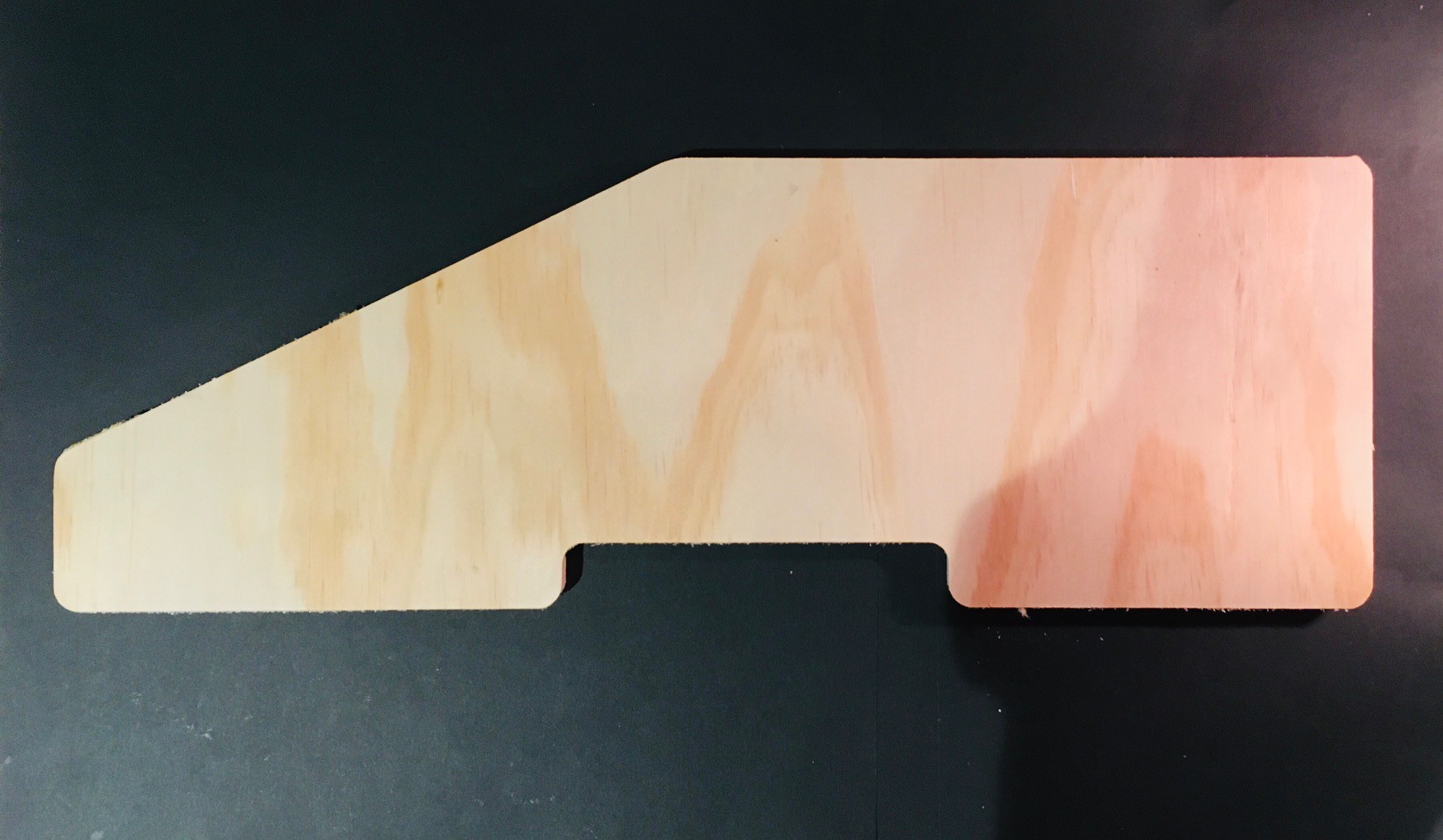
This of course is a Sol-20 side piece that I cut from a scrap piece of plywood I had lying around. I wasn't about to risk my expensive slab of walnut on my first attempt! But it went well so I took the plunge.
![]()
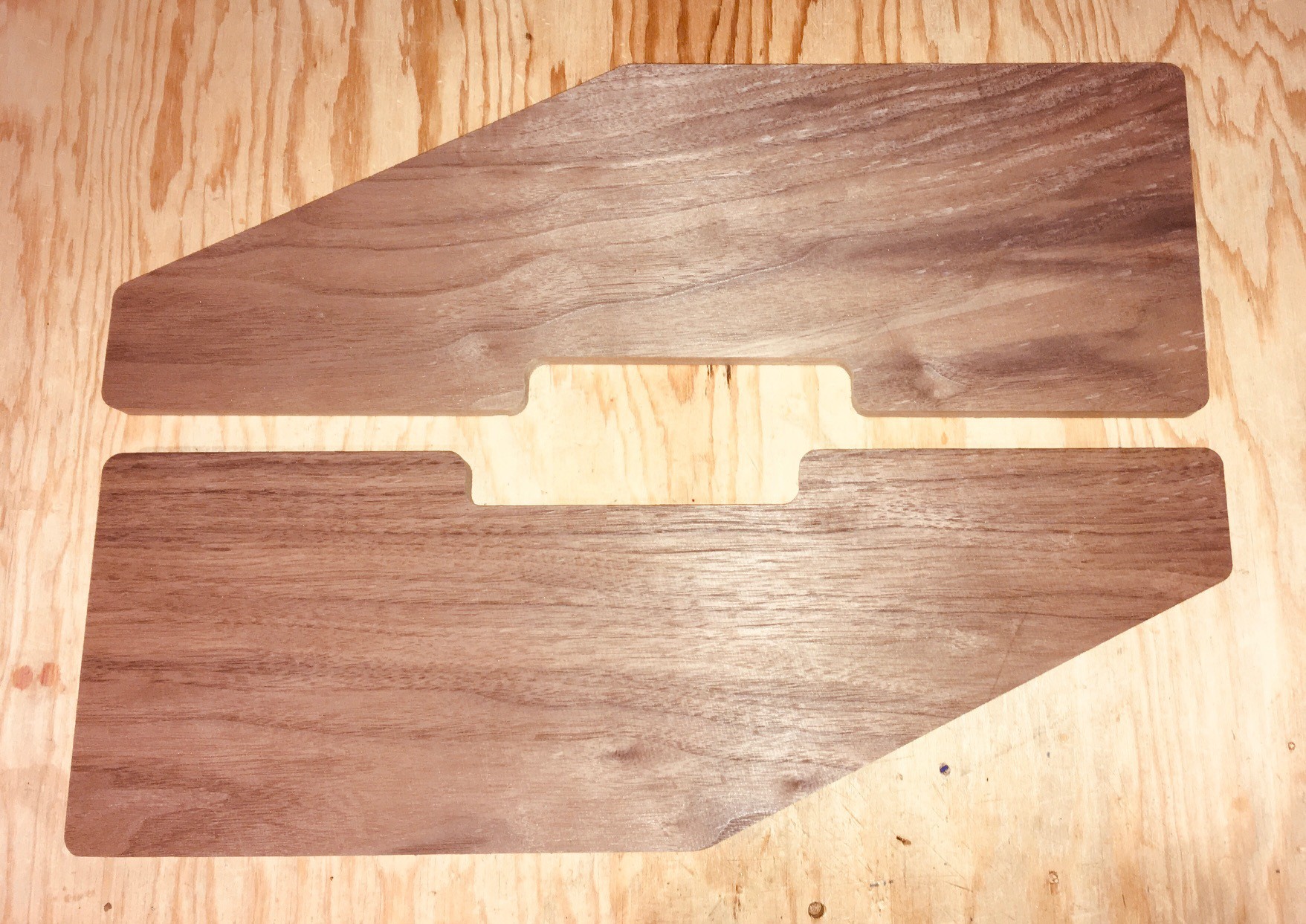
And thankfully that went OK too. But I was not quite done. The CNC just cut out the side shapes. I wanted to get the nice rounded edges as well. I learned that this was accomplished by using a round over routing bit (pretty clear at this point that I'm not a woodworking guy right). With a little more expert coaching from some lab mates I got this done as well learning how to use a handheld router.
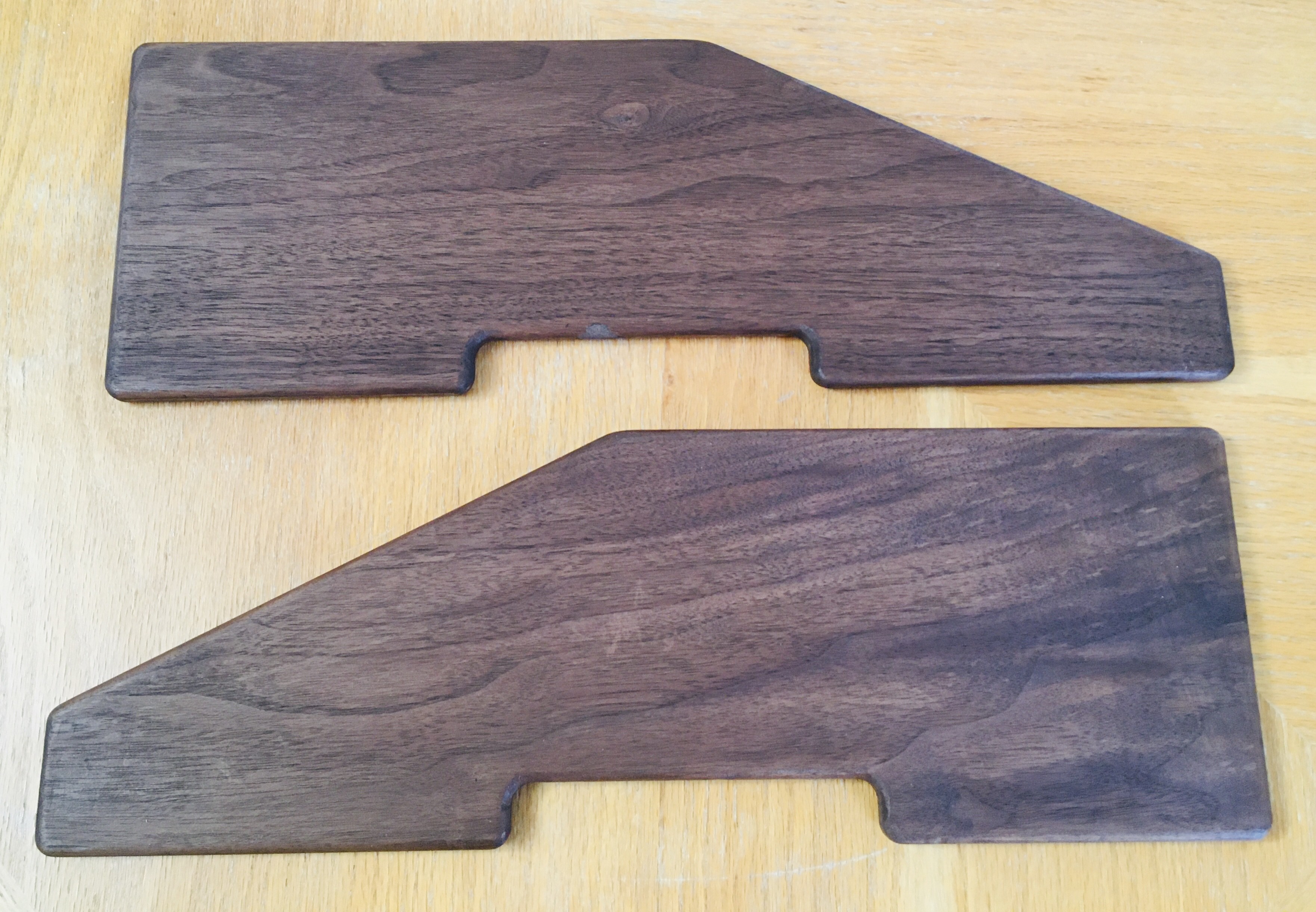
Finally to finish off the pieces I applied some Minwax Walnut Gel Stain. This couldn't have been easier. The stain is applied evenly to the wood with a brush or rag and after only 3 minutes the excess is removed by wiping it off following the grain of the wood with a rag.
![]()
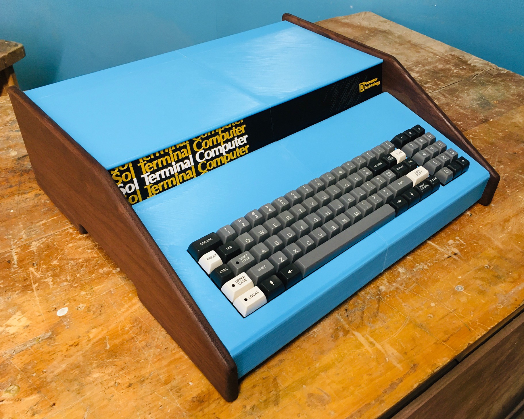
This afternoon I installed the walnut sides onto my Sol-20 reproduction.
![]()
So happy with the result.
-
Wiring the Keyboard
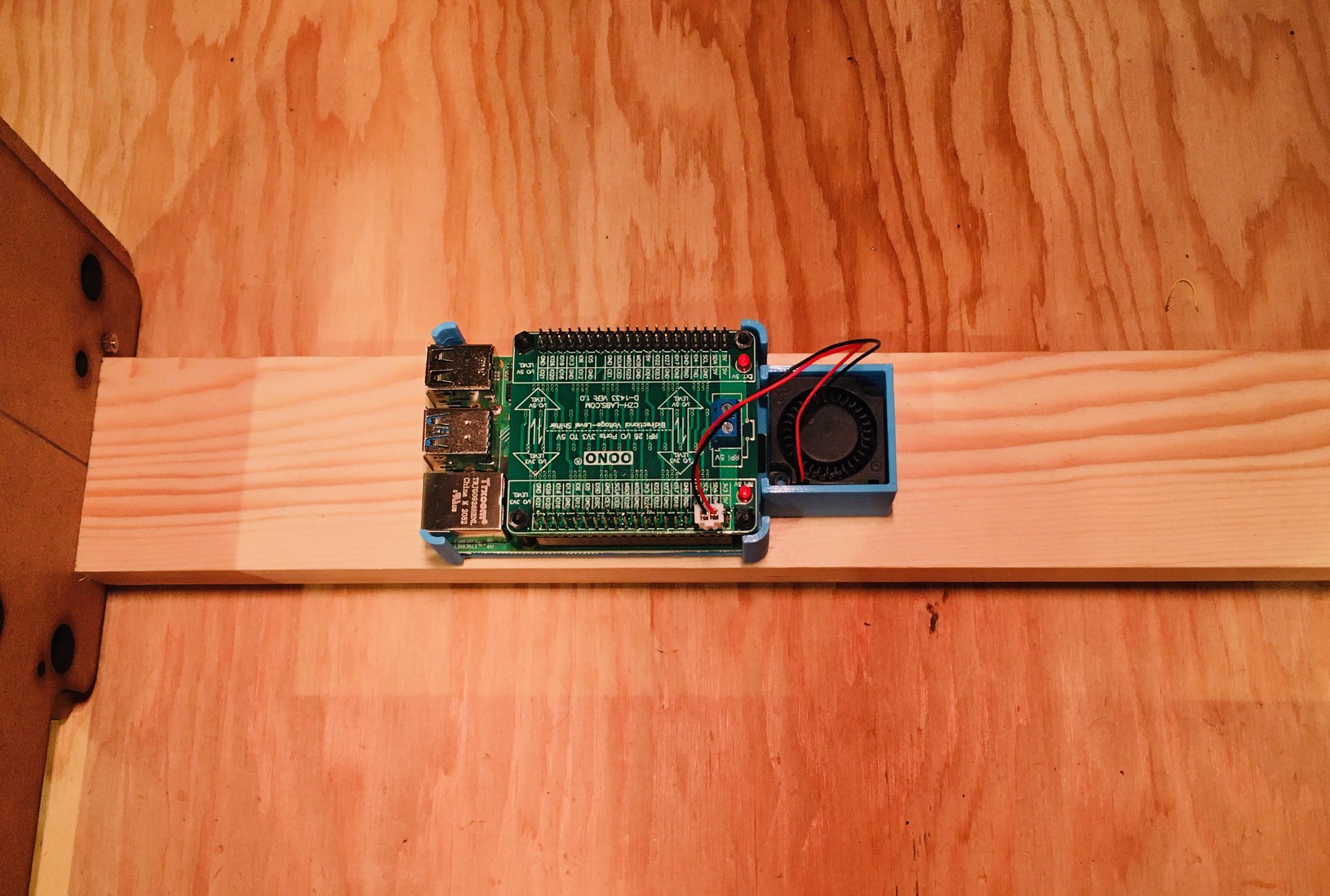
11/08/2021 at 21:57 • 0 commentsThe keyboard encoder is expecting 5V while the Raspberry Pi 4 operates at 3.3V. So to overcome this I purchase a Voltage-Level Shifter Module from Amazon. I also printed a "caddy" to hold the Pi 4 in place and added a small 30 mm x 30 mm x 10 mm blower fan for good measure to keep things cool. The fan I used is from Amazon: GDSTIME 3cm 30mm x 10mm 5V DC Brushless Small Blower Cooling Fan, with Dual Ball Bearings. The fan and the keyboard will be run off of the Pi's power supply. The Pi is secured in place to the caddy with two sided tape.
![]()
I then mounted this unit onto the back support of the Sol-20 frame again using two sided tape. The USB and HDMI ports are facing to the rear of the unit.
![]()
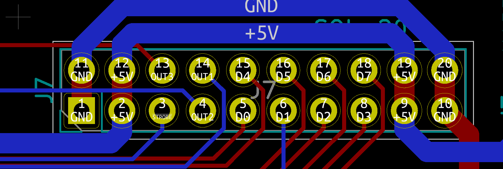
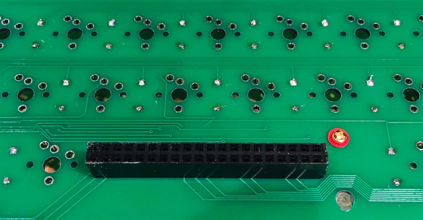
So we are ready to wire the keyboard to the Pi. Here is what the Sol-20 header pinout looks like.
![]()
And the Raspberry Pi level shifter hat.
![]()
So here is how I wired the keyboard. Note that for the exception of +5V and GND lines which are wired to the 3.3V side or the level shifter, all of the other connections are wired to the 5V side.
Keyboard Encoder Raspberry Pi Description 5V 5V Power GND GND D0 GPIO6 Key 0 bit (low) D1 GPIO13 Key 1 bit D2 GPIO19 Key 2 bit D3 GPIO26 Key 3 bit D4 GPIO21 Key 4 bit D5 GPIO20 Key 5 bit D6 GPIO16 Key 6 bit D7 GPIO12 Key 7 bit (high) STROBE GPIO5 Key ready on falling edge. OUT1 GPIO23 LOCAL button. Toggle. HI when LED on. OUT2 GPIO22 BREAK button pressed when rising edge. OUT3 GPIO24 RESET button pressed when falling edge. Here is what the wiring looks like.
![]()
I'm investigating a BREAK key issue with Dave, but otherwise everything is working great. The keyboard is now integrated with the emulator. Getting close. Very exciting.
-
Mounting the Keyboard
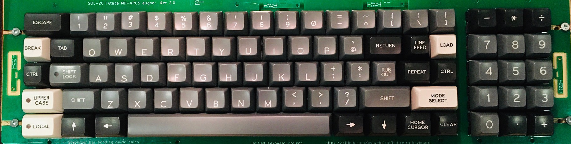
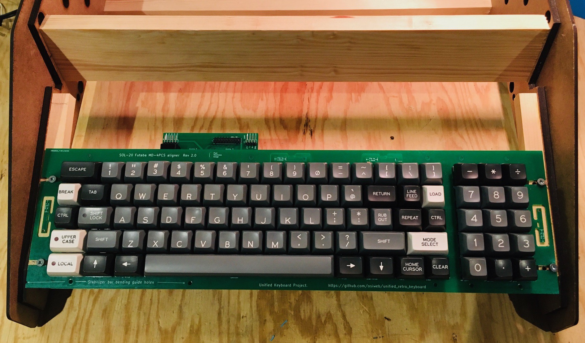
11/08/2021 at 21:32 • 0 commentsI wired the keyboard up to the Raspberry Pi 4 I will be using to run the Sol-20 emulator. I did enough testing to ensure that all of the keys are working as expected. At first some of the keys were not responding, but with Dave's help I discovered I had missed installing a couple of jumpers and also I found a solder bridge that shouldn't have been there. When I was satisfied all was well I installed all of the keycaps.
![]()
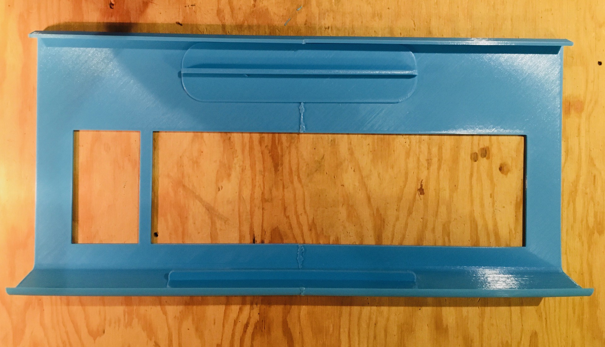
Using the finished keyboard I was able to refine the measurements for the keyboard cutouts in the front panel. I reprinted the panel with the changes in the "new" light blue filament and reinforced it as I had the first one.
![]()
I added some 1/2" x 1/2" wooded supports for the keyboard on the side frame positioned about 2mm below the top edge that the front panel will be resting on.
![]()
Using the printed front panel as a guide, I positioned the keyboard and locked it in place with four #6 x 5/8 inch wood screws.
![]()
-
Keyboard Construction
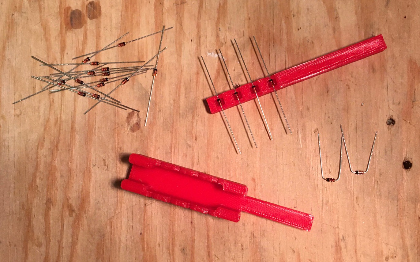
10/27/2021 at 01:00 • 0 commentsMy Fubata MD-4PCS key switches finally arrived! Time to get the keyboard put together. The first step was to add the 85 IN4148 diodes. To save some time I printed a diode lead bender from Thingiverse.
![]()
I was super careful to double and triple check the orientation of each diode since trying to replace one after all the switches are installed would be very hard.
![]()
You can also see that I have installed the screw-in stabilizers for the space bar and Shift keys plus the three limiting resistors for the Local, Upper Case, and Shift Lock key LEDs. On the back a 2x20 pin female connector was added to mate with the encoder.
![]()
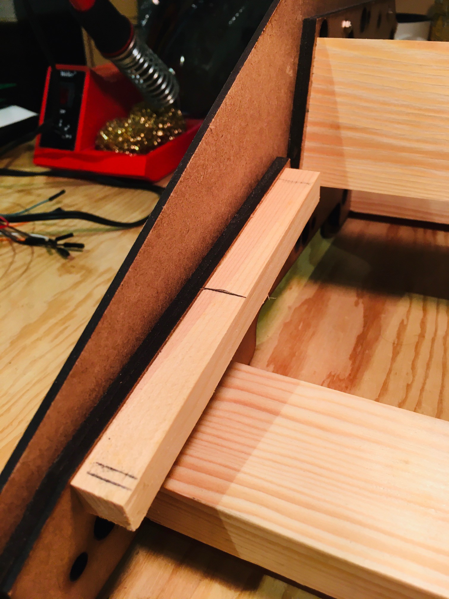
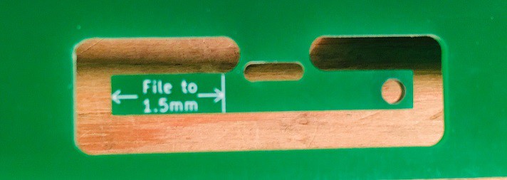
On the aligner PCB there are four extenders to be used with the Spacebar and Shift Stabilizers.
![]()
Snip these off and as the text instructs you have to file down one end so that it is 1.5 mm thick so they will fit into the keycaps.
![]()
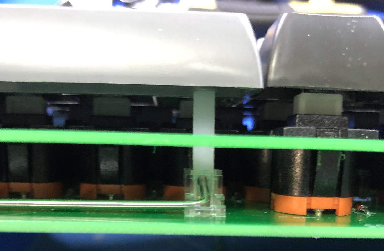
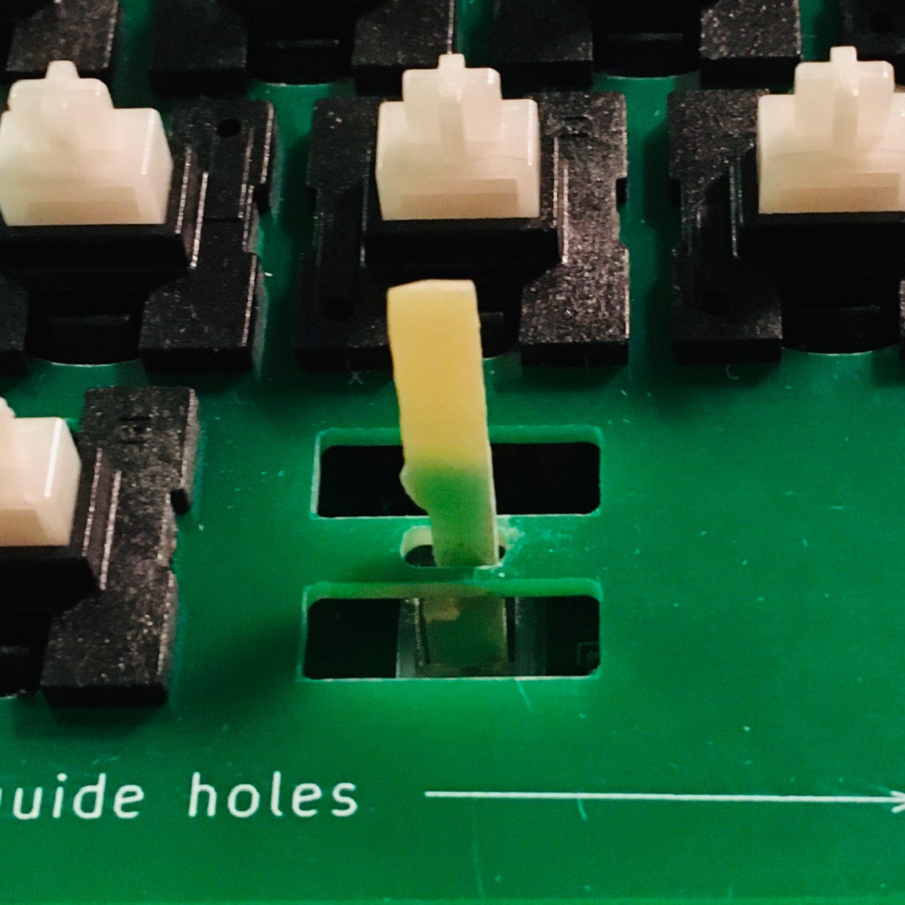
This is how they will be installed when you first start adding switches attaching the aligner and keyboard PCBS.
![]()
Make sure that they pass through the openings in the aligner as pictured above.
I followed Dave's advice adding the switches.
- Snap a few Futaba keys into the aligner, perhaps 3 or 4 evenly spaced per main keyboard row, and one at each corner of the keypad. Then fit the aligner with keys to the keyboard PCB. At this point you should have the extenders connected and ready to go as pictured above.
- Solder in one lead of each switch. Then, go through all the switches and reflow each solder joint while applying tight clamping pressure (with your fingers) to push the aligner and PCB together so each switch is flush. This makes a torsion-box structure for the keyboard.
- Now solder the second lead of each switch.
- Now snap in a few more keys, spaced evenly between the already installed switches, and repeat the same procedure as above.
- Now install the rest of the switches, snapping in enough switches to fill one of the gaps between keys, then soldering all the leads at once.
![]()
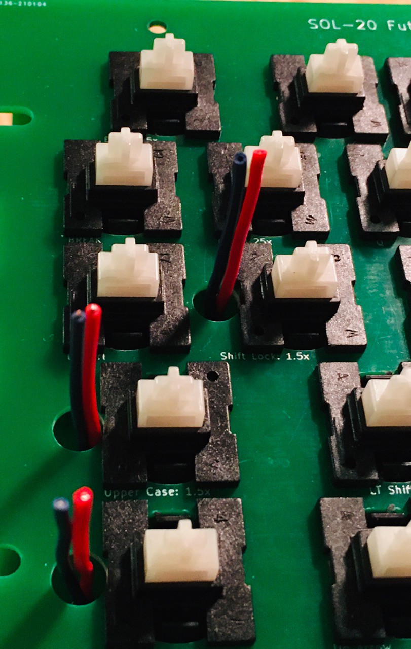
Here is what I have so far. The wires you can see on the left had side of the keyboard are for the Local, Upper Case, and Shift Lock key LEDs since I found that the leads on the LEDs that I had were too short.
![]()
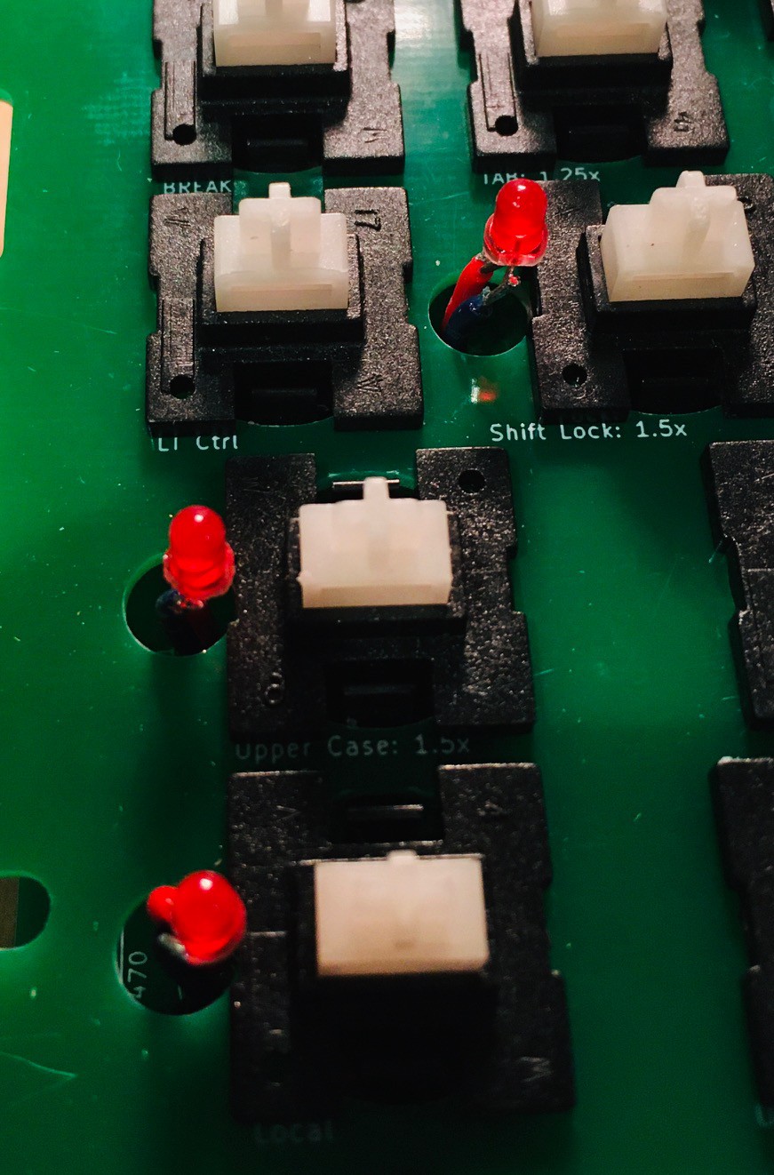
Using one of the keycaps I cut the wires so that when the LED was attached it would extend up into the keycap without touching the top when the key was depressed. Looks like this.
![]()
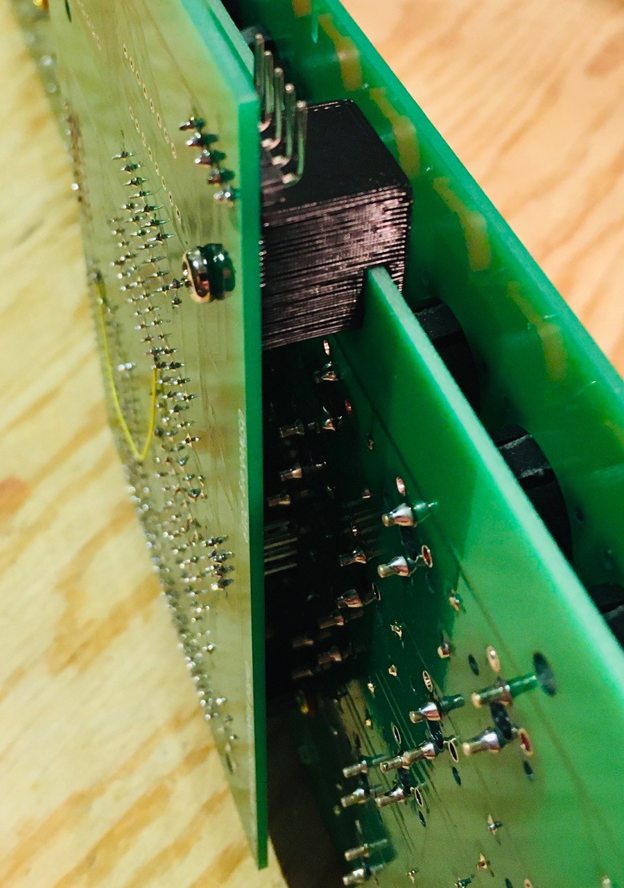
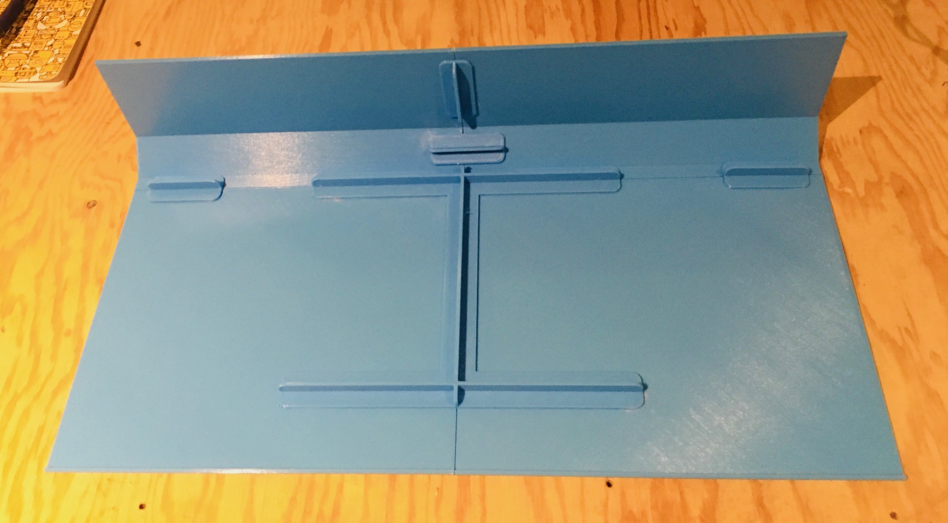
Finally I attached the encoder via the 40 pin connector. There were holes on the encoder and keyboard PCBs but I found they did not line up correctly and would have been hard to reach at any rate. So I printed a brace to secure the front part of the encoder board.
![]()
That's pretty much it for the keyboard. I'll attach the keycaps once I have verified that everything is working as expected.
-
More Skinning
10/24/2021 at 16:12 • 0 commentsI finished the cover for the back part of the Sol-20. I had to print it in four parts which I glued together and braced.
![]()
If I get another 3D printer it will have a 500 mm x 500 mm print bed for sure. Or maybe I can just get Ivan Miranda to print these large parts for me ;-)
At any rate the panel fit perfectly on my Sol-20 frame.
![]()
Seeing more of the light blue convinces me that it's my preferred color choice.
-
Logo
10/23/2021 at 00:42 • 2 commentsOne of the things that makes the Sol-20 so memorable is the logo bar of yellow/orange lettering that runs the full width of the body. Stunning. Needless to say I wanted to do a good job of reproducing the logo.
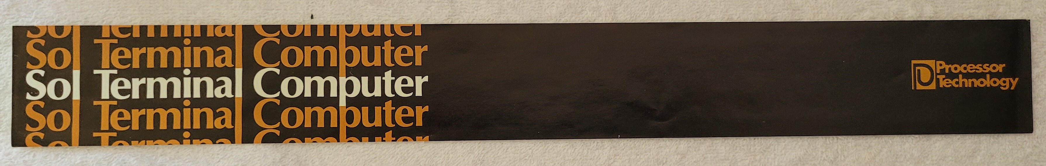
Again I have to thank redjr16 who sent me a great picture of the logo from his machine.
![]()
With his picture, and knowing the dimensions of the logo (width 446 mm), I brought the image into Fusion 360 as a Canvas and calibrated it within fusion to it's actual size. Using Fusion drawing tools (mostly splines) I "traced" the letters and icon and ended up with a sketch of the logo.
My plan at this point was to save the sketch as a DXF file, bring it into Inkscape, add the colors, and print the logo onto cardstock which is what was done on the original Sol-20. I even had a piece of acrylic cut to size to go in front of it to protect it, again like the original.
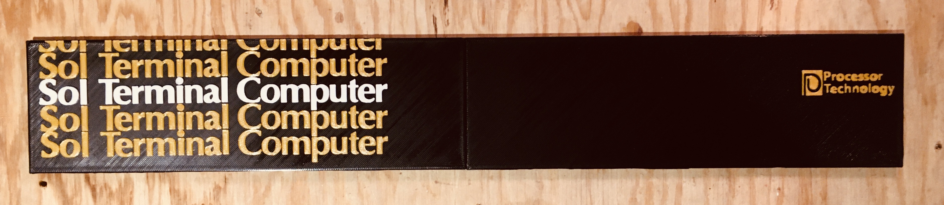
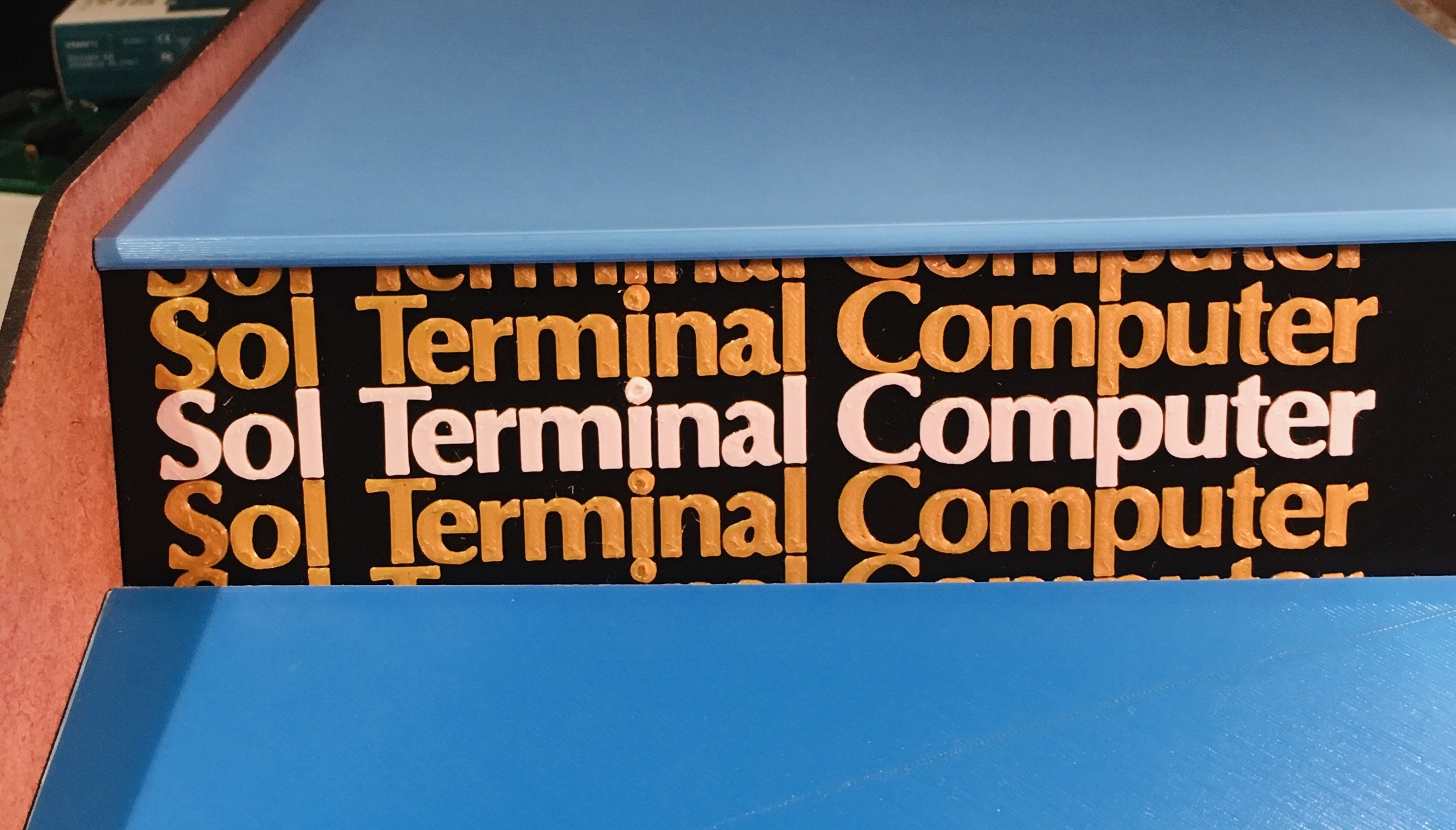
I have had some success in previous projects "drawing" text by extruding the letters and printing them in a different color by pausing the print at the appropriate layer and switching the filament. So I decided to give this a try. To my delight this worked better than expected.
![]()
The small amount of relief afforded by the extrude characters makes them really pop. So as not to waste, I am using the acrylic piece as a backing for the printed logo which is only about 1 mm thick.
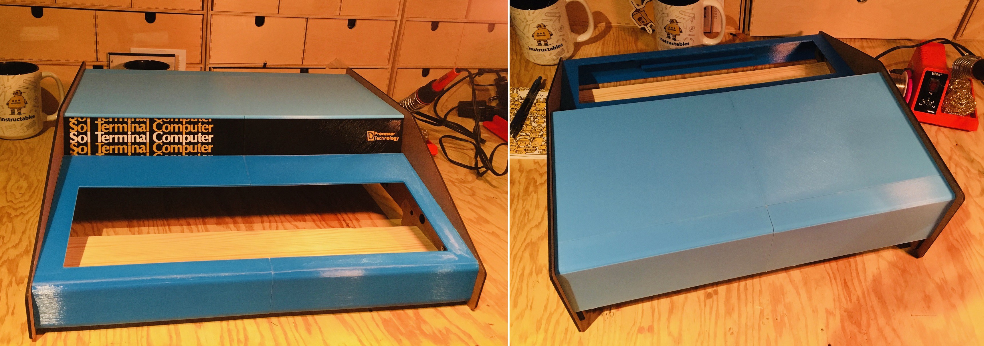
Here is a sneak peek at the logo bar in place. I have only just started printing the top panel.
![]()
You might be asking "Hey Mike what's with the two different blues?". I tried the lighter blue on the top panel and I like it better, so I will eventually be reprinting the keyboard panel to match.
-
Measure Twice...
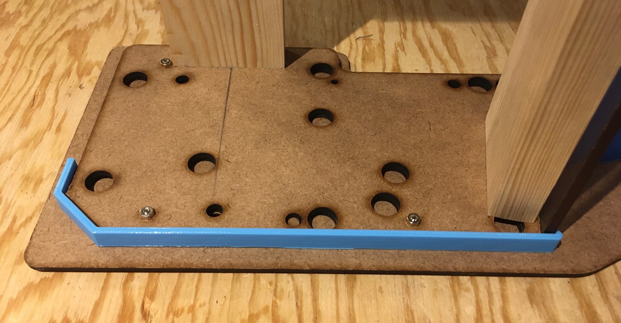
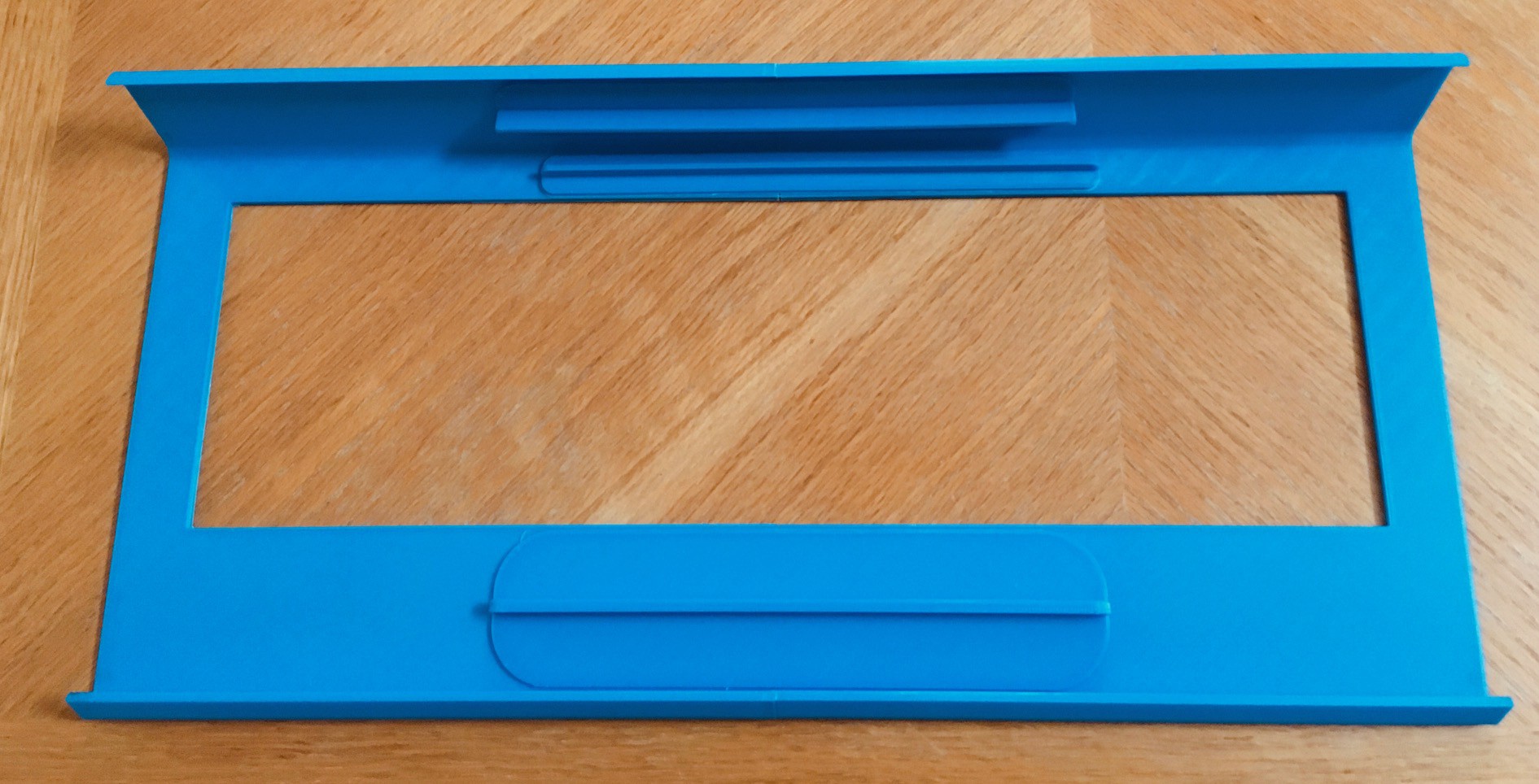
10/21/2021 at 23:51 • 0 commentsSo I'm working on the blue console piece that extends from the logo to the back of the Sol-20. Having the DXF for the inside panel that this rests on is a big help getting the measurements right, but since the total print time for this piece is 11 hours I really wanted to make sure the fit is correct. So to that end I invested 30 minutes to print a 10 mm slice of this piece just to be sure.
![]()
On the right you can see that the console panel extends a bit past the acrylic plate that covers the logo with a little overhang. On the left it wraps around...oops
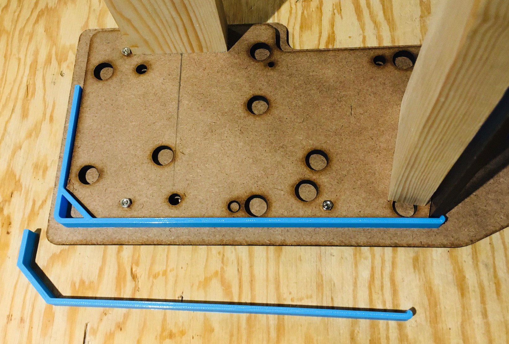
Ironically at this point in writing the log I realized that the curved part at the back was wrong, and should not just follow the inside panel like that. It needed to look more like this:
![]()
So a few tweaks to my model and another 30 minutes of printing and I get this:
![]()
Much better. I feel a lot more confident now kicking off those long prints.
Maybe I should change the title to Measure Thrice...
-
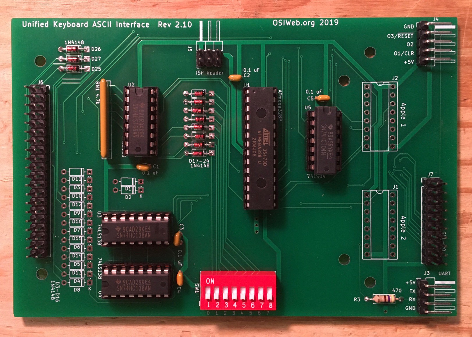
The Keyboard Encoder
10/21/2021 at 04:01 • 0 commentsI talked about Dave's very flexible encoder in my previous log and in this one I'll cover it's construction.
I'm still waiting for the keyboard switches to arrive (last seen in Chicago IL), but the hardware for the encoder hit my mail box a couple of days ago. I followed Dave's assembly notes on GitHub. Here is what the end result looks like.
![]()
The assembly was all pretty straight forward. Nothing to see here. What was a little trickier was flashing the ATmega328P with the encoder firmware. Dave uses Atmel Studio 7 to build the firmware and a high end Atmel-ICE programmer burn the chips. A little out of my price range.
Fortunately you can use practically any Arduino as an AVR programmer. There is a lot of sometimes confusing information online on how do do this. I'll just tell you about what worked for me.
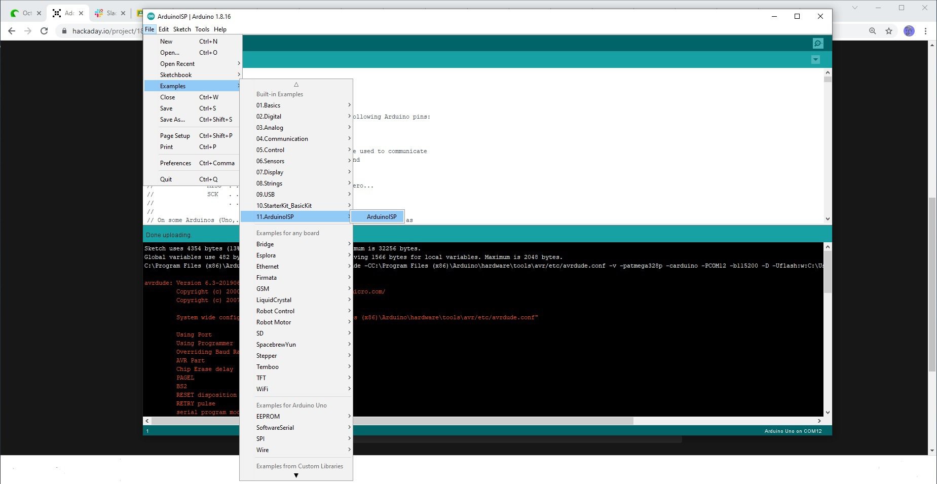
I started by opening the Arduino IDE and loading the sketch ArduinoISP.
![]()
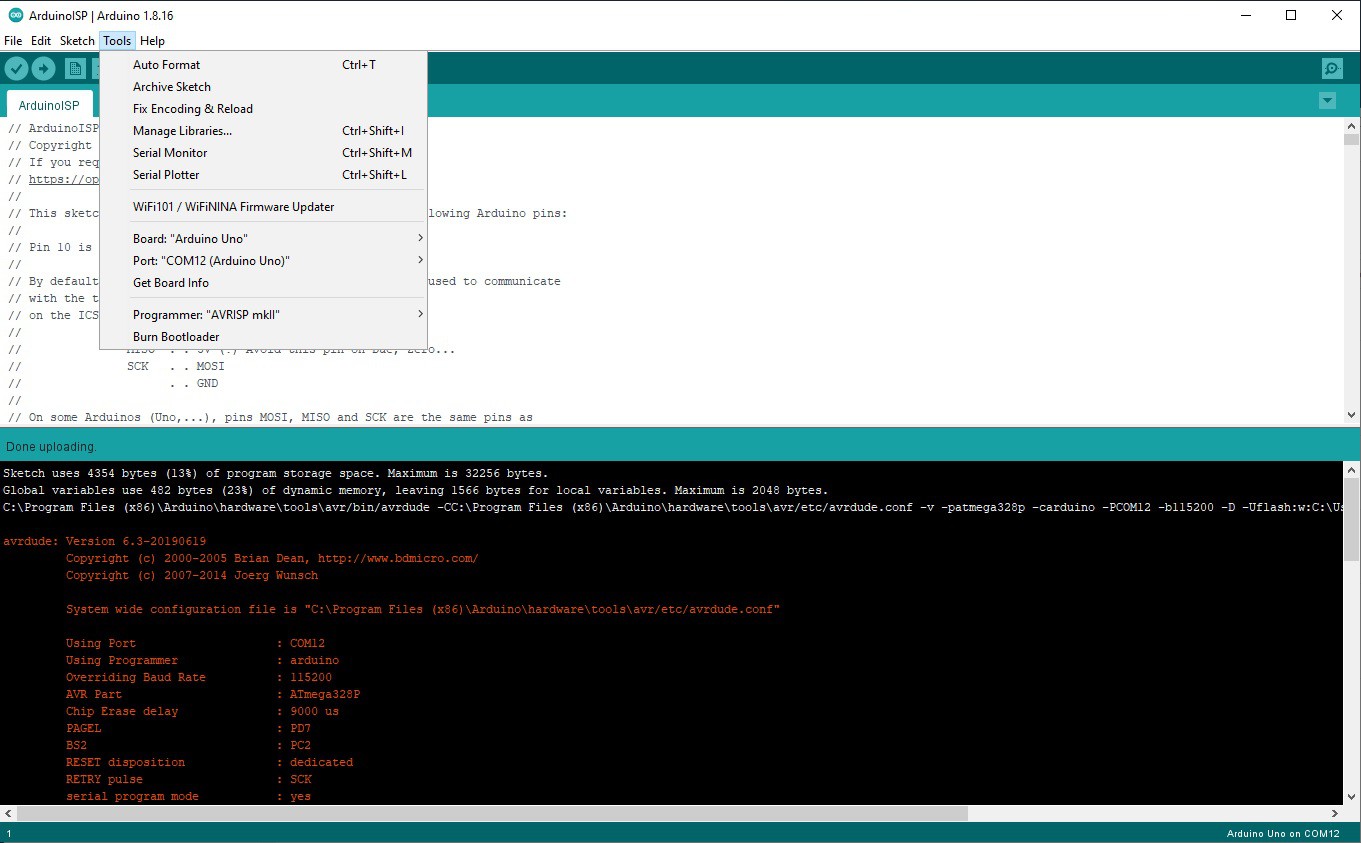
I had a Arduino UNO attached on COM12 so I compiled and uploaded ArduinoISP with the following settings.
![]()
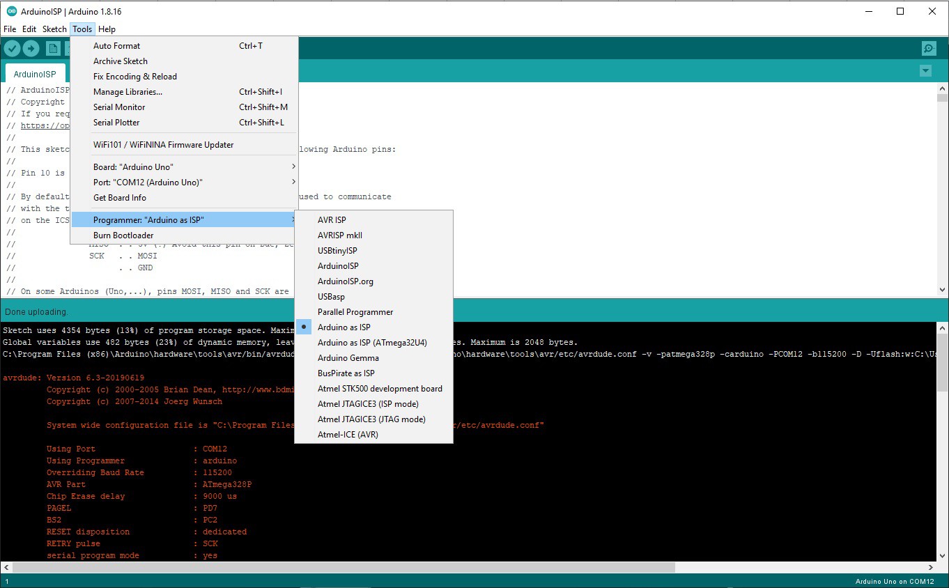
Then I switched the Programmer: setting in the IDE to Arduino as ISP.
![]()
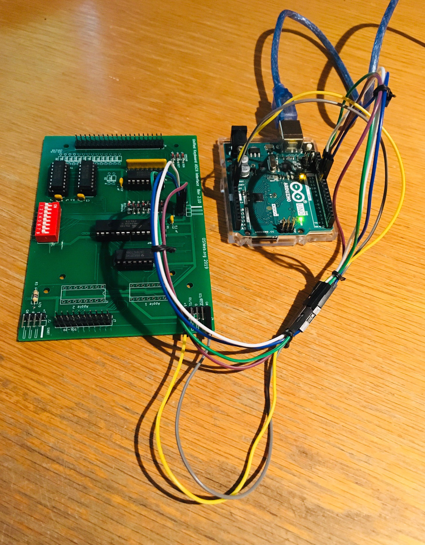
Using jumpers I wired the Arduino UNO to the encoder board's ISP Header with the following connections.
Arduino ISP Header Pin 10 Pin 5 (RESET) Pin 11 Pin 4 (MOSI) Pin 12 Pin 1 (MISO) Pin 13 Pin 3 (SCK) +5V +5V GND GND Here is my setup.
![]()
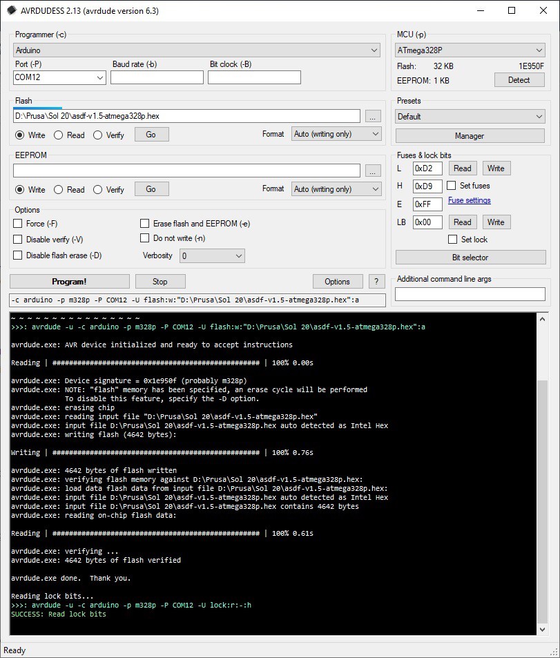
The Arduino IDE uses a command line program called avrdude under the covers to flash AVR devices. Getting the command line parameters to this program correct can be tricky. Fortunately there is a GUI called avrdudess which can be found here that I downloaded.
I didn't have an environment setup to build Dave's encoder firmware, but he was kind enough to send me the latest build's HEX file. At this point I was all set to flash the ATmega328P on the board. I fired up avrdudess.
![]()
I altered the following inputs:
- Changed Port to the com port the UNO was attached to: COM12.
- Set the Flash input field to Dave's firmware HEX file.
- Changed the MCU to the target device ATmega328P.
- Entered the Fuse settings that Dave provided: Low 0xD2, High 0xD9, Ext. 0xFF.
Then I pressed the Program! button. You can see that the writing and verification all checked out so the keyboard encoder is ready to go.
-
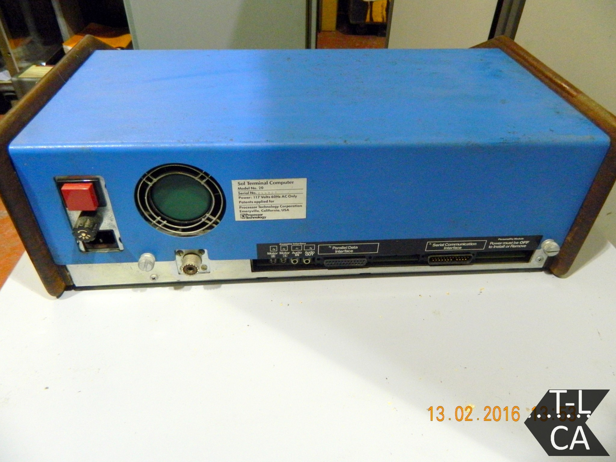
The Sol-20 Keyboard
10/14/2021 at 02:18 • 4 commentsThe keyboard in the Sol-20 was a capacitive keyboard made by Keytronic. These keyboards had a great feel, but unfortunately, the foam pad present in each key deteriorated over time and virtually all keyboards of this type failed. To be fair it has been 45 years since the Sol-20 was introduced.
If you are lucky enough to find a vintage Sol-20 for sale (and can afford to buy it) you will probably be faced with this keyboard issue. Fortunately all is not lost. One option is repair. Geoff Harrison has figured out a way to make his own foam pads, and has a nice write-up on how he did it. Please see Geoff's web page on how to repair a Sol-20 Keyboard. Also Texelec has a 105 key replacement pad set at a reasonable price.
The second option is to replace the keyboard. I have already mentioned Dave from osiweb.org who has designed a complete replacement keyboard for the Sol-20 using modern Cherry key switches. While not an exact replica, Dave has gone to great lengths to reproduce the look of the original keyboard, including having a set of custom Sol-20 specific keycaps manufactured. Dave's keyboard will drop right into an original Sol-20. So cool.
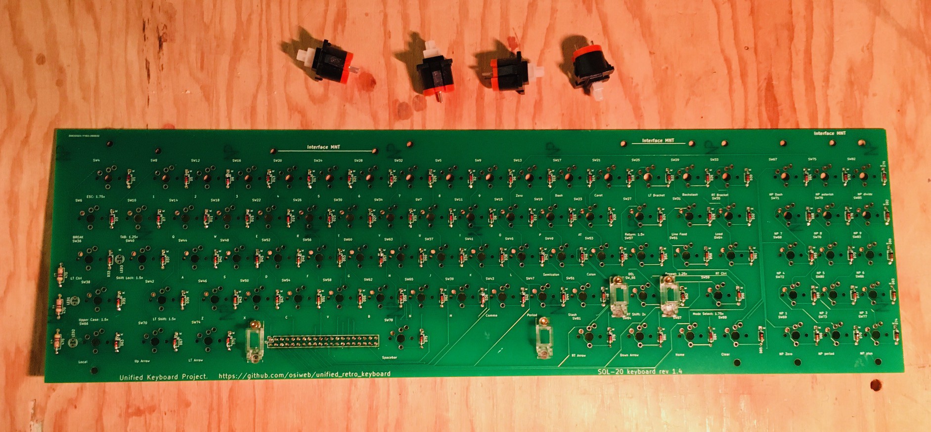
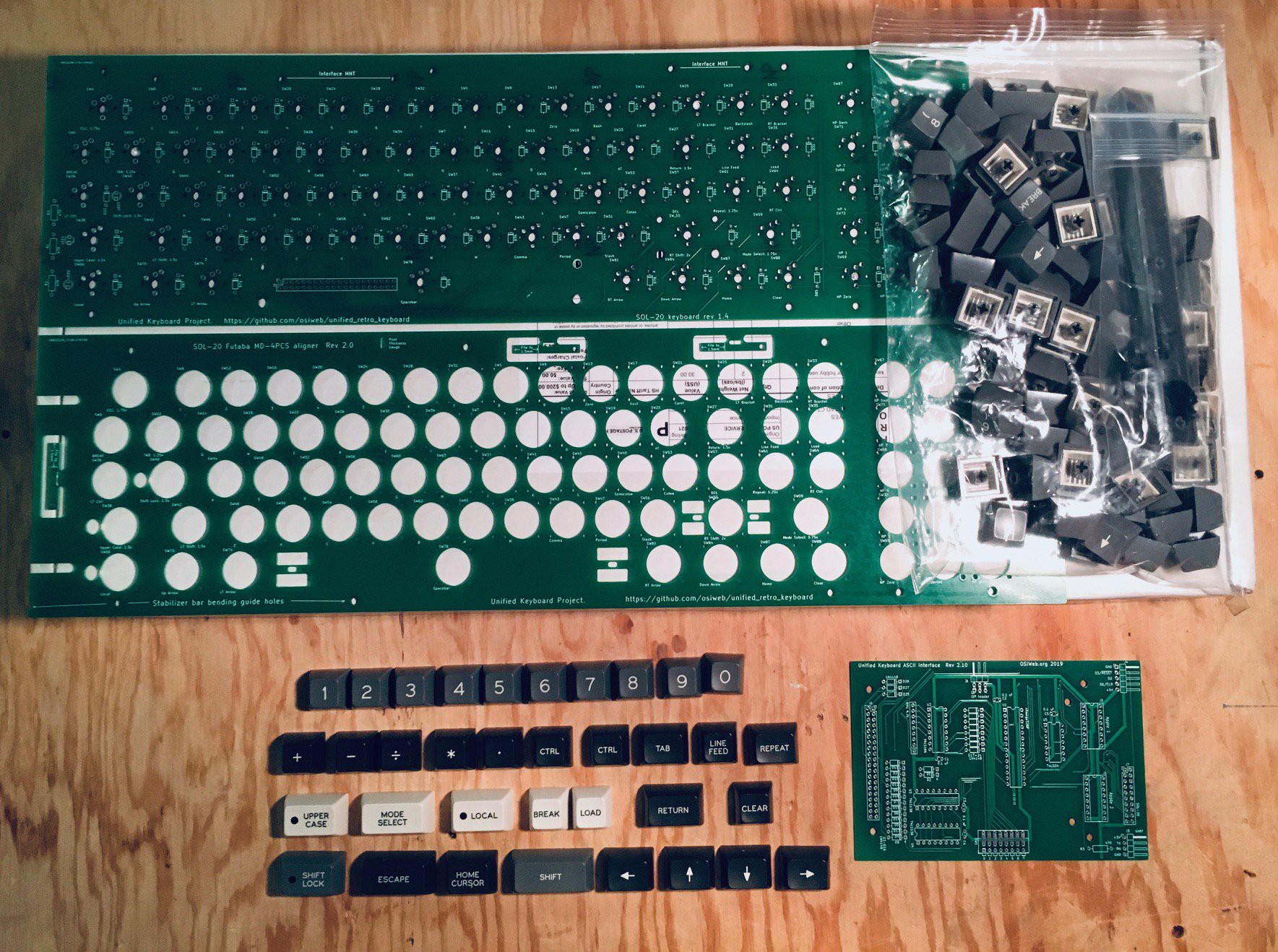
Fortunately Dave's keyboard is also perfect for someone trying to make a Sol-20 reproduction. I received Dave's keyboard kit yesterday. Dave offered to ship me an assembled keyboard, but I didn't want to deprive myself the fun of soldering one up myself.
![]()
You can see above the keyboard PCB and aligner for Futaba MD-4PCS switches. The bag to the right is a set of "standard" keycaps. The keycaps below the PCBs are Sol-20 specific keycaps that Dave had manufactured, and the smaller PCB to the right of that is the PCB for a very flexible encoder with the following capabilities (from Dave's GitHub repository):
- Parallel or serial output
- Up to 8 configuration settings via an up-to-8 position DIP switch
- Apple 1, Apple 2, and SOL-20 compatible outputs. Other configurations can be supported by making a custom cable.
- Can decode arbitrary keyboards up 16 rows by 8 columns.
- Supports up to 3 keyboard LEDs
- Supports up to 3 "special" host outputs, such as RESET, SCREEN_CLEAR, BREAK, etc.
I'm chomping at the bit to get started on this but the actual Futaba key switches and some of the other components I need to populate the encoder are still in transit. Patience Michael, patience.
-
Body Building
10/10/2021 at 20:18 • 2 commentsI've been in a bit of a holding pattern waiting for external stuff to happen. For instance my local makerspace is in the process of rewiring the woodworking shop which includes the CNC that I want to use to mill the walnut side panels. In the mean time I have been taking the pre-requisite online courses in order to qualify on that particular piece of equipment.
Similarly I have been waiting for Dave's keyboard kit to arrive (from osiweb.org - a complete replacement keyboard for the Sol-20). According to the USPS tracking it is currently in Toronto which is about 100km from where I live, hopefully this will arrive tomorrow.
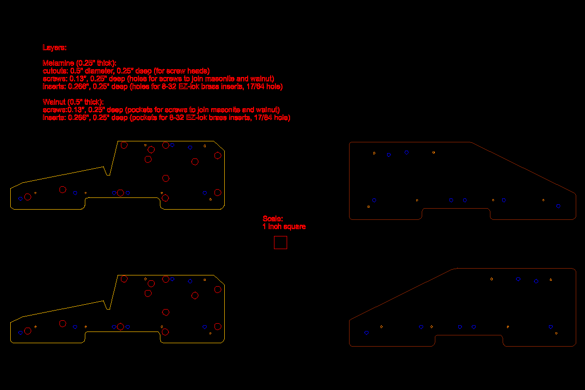
Even though I can't make the walnut side panels right away I decided to get going on the Sol-20 case. In addition to creating the reproduction keyboard, Dave has also produced DXF files for the side panels.
![]()
As you can see there are two distinct parts. There is the outside panel that will be milled from walnut, and an inside panel onto which the blue console pieces will rest. There are a lot of cutouts on the inside panel that were used to attach internal components from the original design like the 5-slot S-100 bus cage and power supply. In my much simpler reproduction these will not be used.
With the side panels pretty much a known quantity, there were still many unanswered questions. For instance how wide are the blue console pieces? I know the size of the keyboard cutout from Dave's KiCad files, but how is it positioned relative to the edges of the case?
Well redjr16 to the rescue. Rick, who actually owns a Sol-20 (I'm totally jealous), was kind enough to take the time to answer these questions, take pictures, and more. Thanks Rick!
![]()
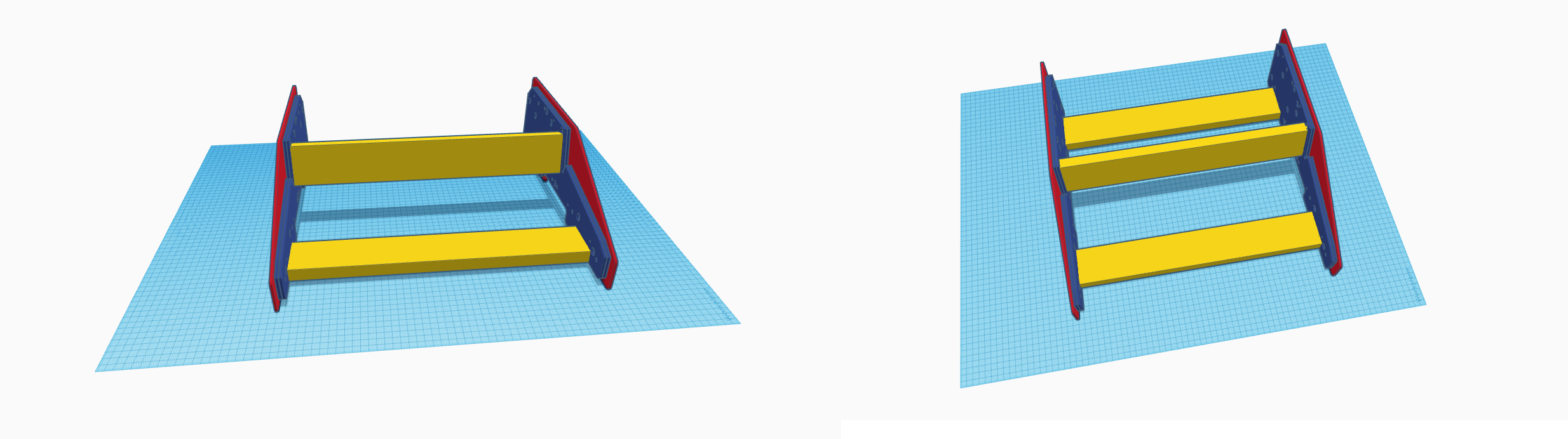
With these measurements I was confident that I could produce a Sol-20 body that was pretty close to the original's. I loaded the DXF files into Fusion 360 and produced STL files for each of the side pieces. Then I brought these STL files into TinkerCAD so I could noodle around with the design. Here is what I ended up with.
![]()
I used the laser cutter at my makerspace to cut four of the inside panels (blue) and two of the outside panels (red) from 3 mm hardboard. The outside pieces will be used as templates when producing the final walnut panels, but in the mean time I can use them as stand-ins while I work on the case panels. The cross pieces (yellow) are 1" x 3" pine cut to 434 mm lengths and are attached to the inside pieces with #8 x 1 1/4" flat head wood screws (in which the heads should end up being flush with the panel). Outside pieces are for the moment bolted to the inside with M3 x 12mm bolts and nuts using existing holes.
![]()
Using the inside panel DXF outlines as a guide, and with additional pictures from Rick, I modelled the keyboard panel seen in the rightmost photo above. I lucked out because the width of the panels (446 mm) will just fit on my printer if split in two. The pieces are then glued together and reinforced with cross beams.
![]()
The panel is 3 mm thick which seems to be sufficient to prevent sagging in the middle. It shouldn't be too hard now to finish the rest of the console pieces.
Sol-20 Reproduction
I am making a full sized Sol-20 reproduction, the first fully assembled microcomputer with a built-in keyboard and television output.