 kwikius
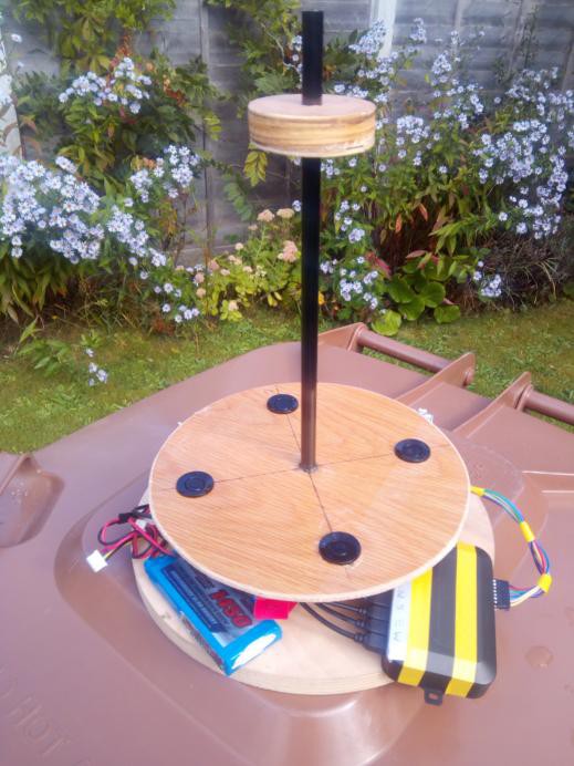
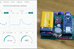
Testing the prototype using a household fan to provide the wind. Wind sensor is mounted on a turntable. The Arduino output goes to ESP32 via serial port. ESP32 serves real time web page showing the data in graphical form.
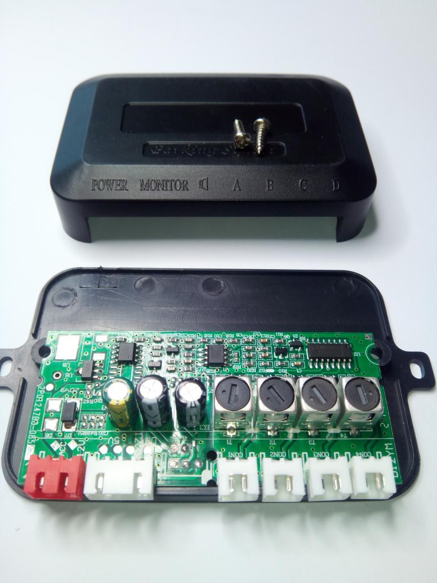
The car reversing kit is available on Ebay for under £10.

Video showing what is in the box and initial thoughts on how to hack the control box pcb for the wind sensor.
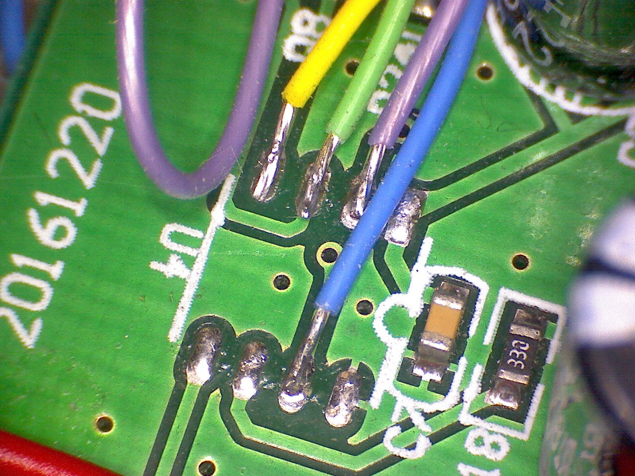
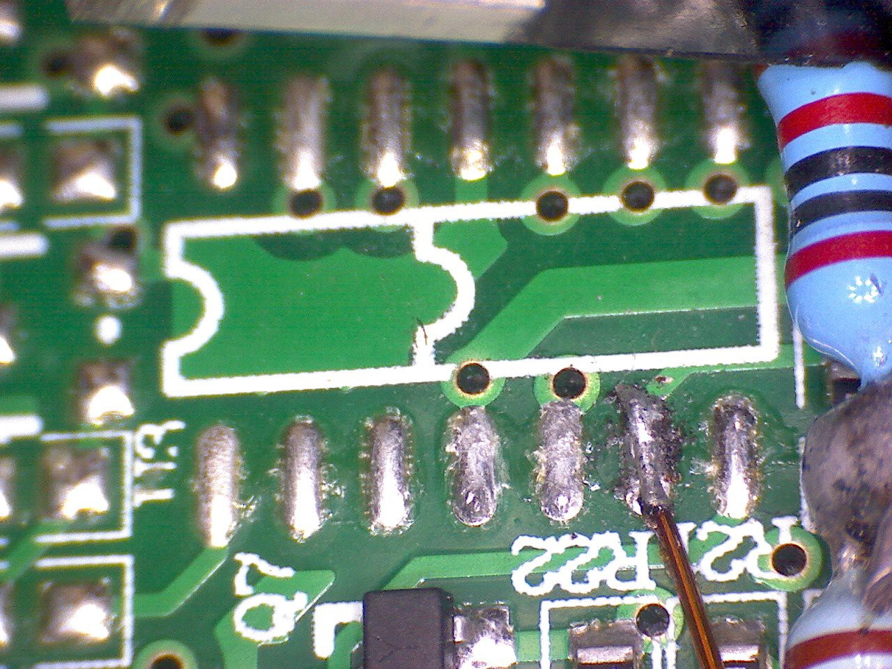
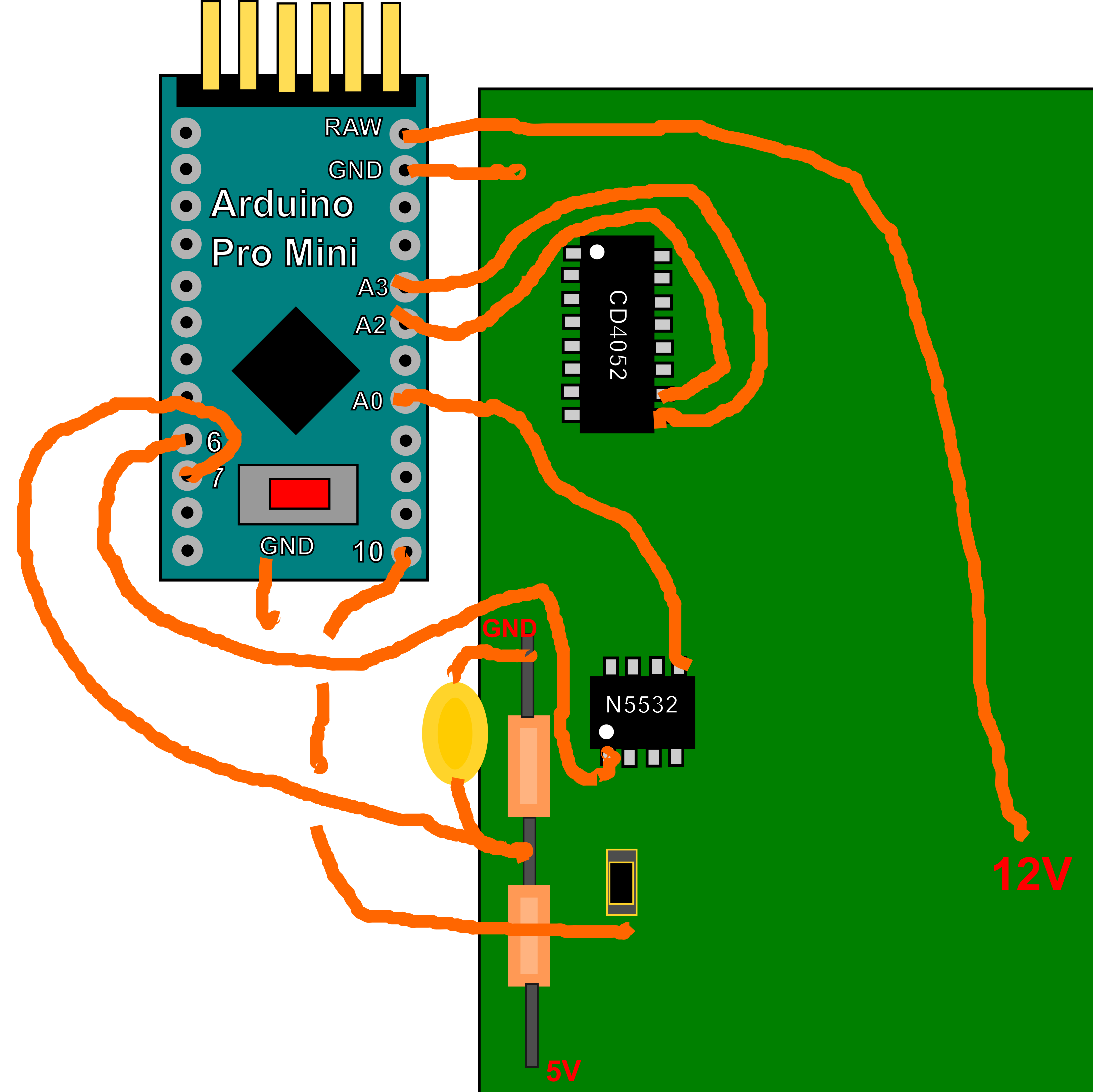
The PCB inside the control box
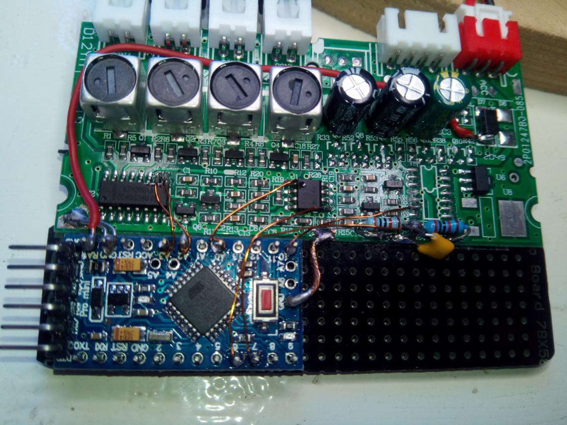
The Arduino Pro mini in place on the car reversing sensor pcb.

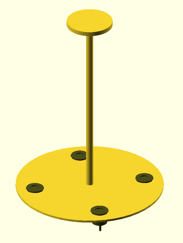
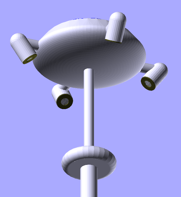
The prototype was designed to be as simple as possible to make. A 210 mm diameter disc of ply with holes for the transducers at 150 mm diameter (cut out using the hole saw supplied with the kit) and 10mm hole for a central spine to support the 65 mm diameter "echo plate", at the top. Spine was 10mm carbon rod, but steel or wooden dowel would work just fine. Vertical distance from sensors to echo plate around 250mm.


 Jithin Sanal
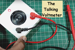
 Sagar 001
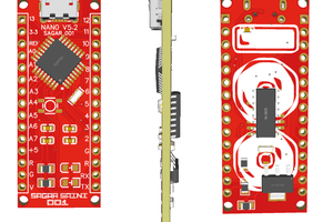
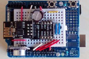
 Augusto Ciuffoletti
Very very nice project. Did you consider the possibility of identifying the existing MCU so that you could just reprogram it without any modification to the he?