 Engin
EnginThese days, I am interested in building a small-scale hydroponic system that can also fit on my desktop to observe closely its performance in growing a plant. I had no previous experience in hydroponics so, I started searching on the internet and decided to go with the flood and drain system. Since it would be an experimental setup, I had to think about my budget to save money. I thought it would be great if the entire planting pot could be 3D printed. I would also definitely need a water pump to pump the nutrient solution. It would be great if the pump could be powered by a USB charger. So I came up with these requirements.
It should be:
- small to fit on a desktop.
- cost-efficient to save money.
- a resemblance to the actual system, which can also be scalable.
- powered by a USB charger or maybe a power bank. Let me rephrase this as low power.
- preferred to be 3D printed.
How will it work?
In summary, the system will work as follows. There will be two tanks piped together. The first tank will hold the plant; the second will be the reservoir which will contain the nutritious water. There will be a controller which will track the time. For example, once every hour during the day time controller will pump the nutritious water from the reservoir to the first tank containing the growing plant and will flood the tank. After and during the flooding, water will be drained back into the reservoir tank. The controller will follow a different watering scheme for day and night time. Therefore, a light sensor will be utilized by the controller.
Discussions on advantages and disadvantages
As far as I have searched from the internet and having watched several hours of YouTube videos, I can list several advantages and disadvantages of this system over other hydroponic systems. Here you can find a brief list of mine.
First, advantages:
- Simple and easy to operate.
- Low power to operate. This is because the pump is only operated a few times during the day.
- Enables enough oxygenation of the roots
- Low probability of fungal growth
- Maintains a lower root temperature
Disadvantages:
- Requires separated tanks for plants and nutritious water
- Probability of low dissolved oxygen in the nutritious water
- Probability of algae growth due to the low dissolved oxygen
Designing the system
Before doing anything, first I searched for a pump on the Internet and I found this:

There were some variations of this pump, but the cheapest one was this which I could manage to buy.
Some listed properties of the pump are:
- 80 to 120 Liter/hour flow rate
- 2.5-6 V DC operating voltage
- 130-220 mA operating current
- 40-110 cm hydraulic head
- 56mm length, 24mm diameter
- suitable for water
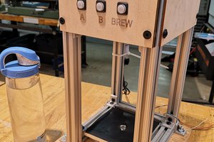
After a few hours spent on modeling, I have designed this planting medium. This design consists of two tanks which are top and bottom. The bottom tank preserves nutritious water and pumps, while the top tank contains clay pebbles and the plant. A form of clay which is called "hydroton" can be used at the top tank, or cocopeat can also be used instead.

Water and air pipes:
To equalize the reservoir pressure with the outside pressure while the pump is operating, we need a small air pipe whose one end is connected to the reservoir and the other end is open in the air. This small pipe also serves a second function. Although it is not guaranteed to work if the growing media is over-flooded with water, this pipe can drain the excess water to the reservoir. The second and the larger pipe is the water pipe which is directly connected to the pump. At one end of this water pipe, there is an elbow connected to direct and adapt the dimension of the pump outlet. At the other end of the tube is a chimney that is used to keep pressurized water flowing downwards into the growing medium rather than spouting it.


 Sean Morton
 M. Bindhammer
 Nicholas DiPatri
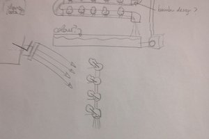
 Roberto Vicente Romero