-
1Prepare the arduino board to be a MIDI output device
In order to transmit MIDI over USB, the firmware of the USB-to-serial chip (a MEGA16u2 chip) needs to replaced. Follow the steps here for best results; ATmega16U2 Flashing MIDI Firmware. Note that once this has been flashed, the USB connection can no longer be used to flash the arduino program code. I used this programmer to do that following flashing the MIDI firmware: Sparkfun AVR programmer. This is tool is optional, but very handy. Otherwise, one needs to constantly switch between firmwares to reflash any changes to the code.
-
2Build the module circuits
- Solder 3-pin male headers to the pads labelled A1, A2, and A3 - these will be receptacles for the potentiometers.
- Solder 2-pin male headers to the pads labelled D1, and D2 - these will receptacles for the LED and the toggle buttons.
- Solder right angles male headers to V1, V2 (facing the other way), A, and D - these will be used to connect to the arduino, or to the adjacent board (in the case of V2)
-
3Build the mini-board circuits
- Solder an 8-pin male headers set in the middle row of each of these boards (I needed 5 boards to cover the power area, the two analogue connections area, and the two digital connections area). I did not use the digital connections double pins on the back of the arduino in this project.
- To either the front row or the back row, connect right angled pins - these will be where the module circuit connections from either the right side of the arduino or the left side of the arduino will connect. In the case of the 5V, and GRN pins, use right angled pins on both sides of the middle, since these will power the modules on either side.
- Push these into the female headers on the arduino appropriately
![]()
-
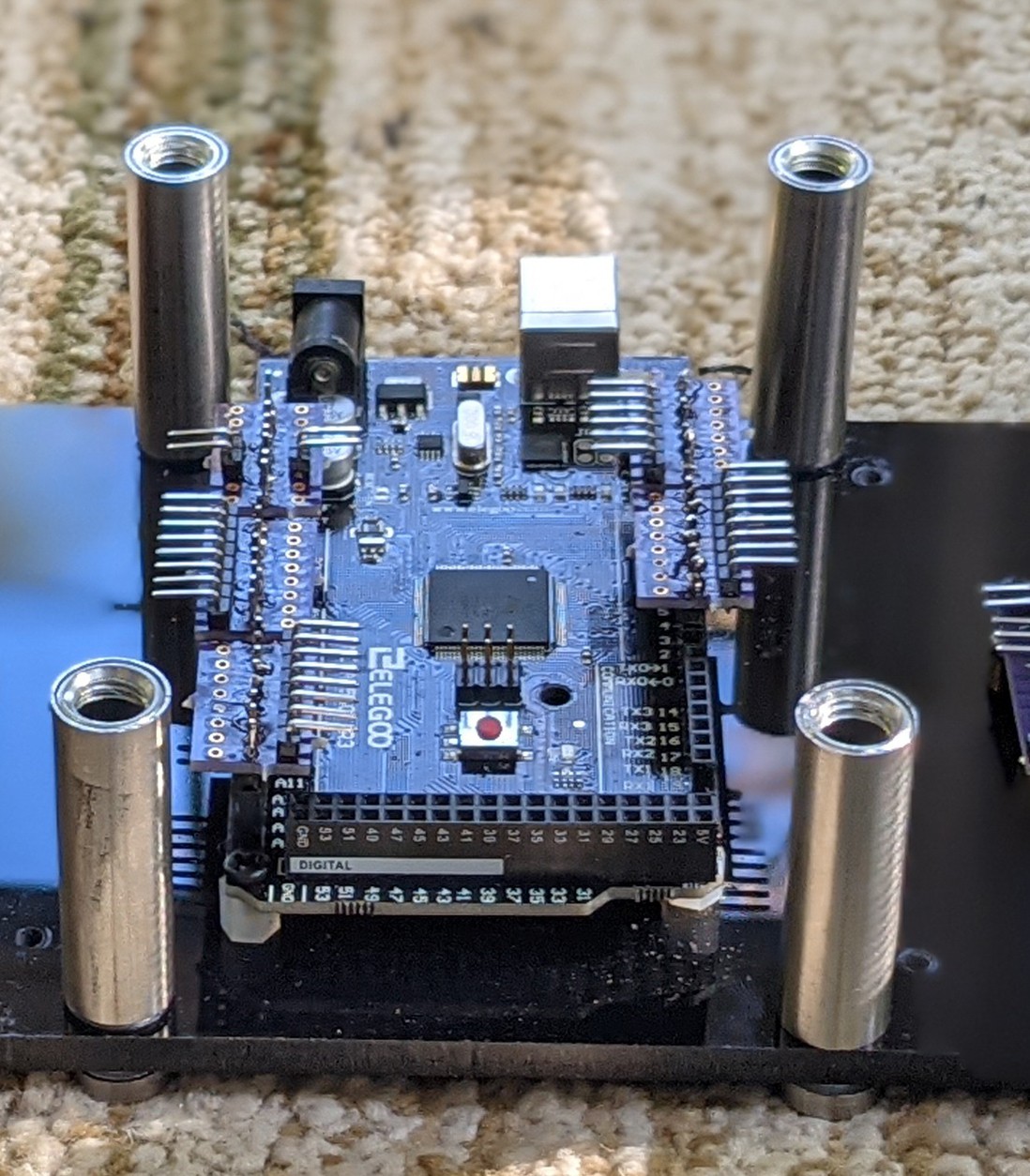
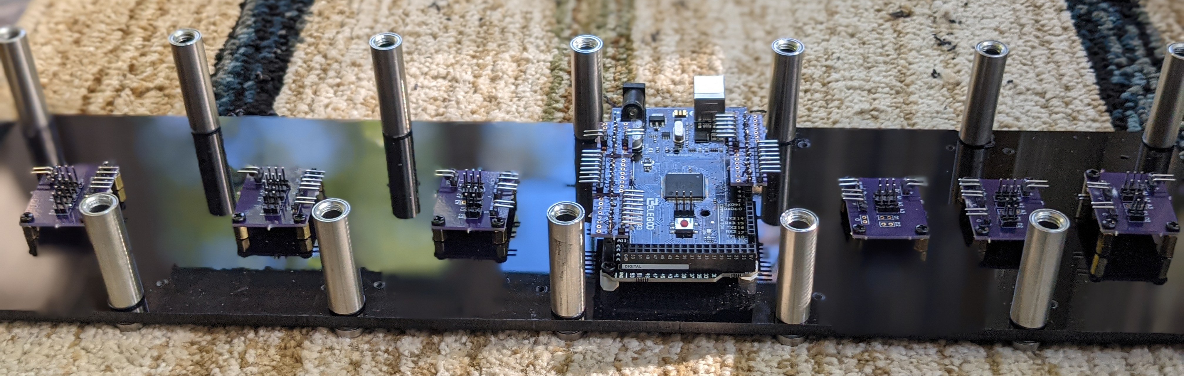
4Assemble the base
- Position and secure each module on the base acrylic using stand-offs in appropriate locations on the base.
- Position and secure the arduino board using stand-offs as well. I used plastic stand-offs.
![]()
-
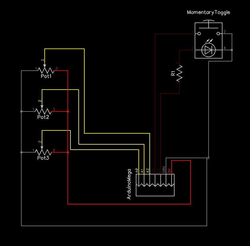
5Connect all the headers
- All the 'A' connectors connect to the analogue pins
- All the 'D' connectors connect to the digital pins
- Attention needs to paid as the C++ code defines which digital pins are buttons and LEDs
Schematic of this connection for one module:
![]()
-
6Install the potentiometers, buttons and LEDs on the top panel
- Install all the pots (and if using, the TRS jack), buttons, and LEDs on the top panel.
- Connect them to the A1, A2, A2, D1, D2 headers on the modules
-
7Attach top to the bottom
Attach the top panel and the bottom panel using the sign holders to complete the assembly.
MIDI Control Board
An Arduino Mega based MIDI Controller device for Guitarix.
Discussions
Become a Hackaday.io Member
Create an account to leave a comment. Already have an account? Log In.