Sagar 001
Hello guys, today we are going to make a remote-control universal switch on/off 3 channel circuit. Though this we can control any load like: fan, light, bulb, TV, charger or any other electrical appliances under 1000watts.
This circuit can be controlled using any IR (infrared) remote, it may be of Tv, A.C or any universal remote. We will build this circuit using very less and readily available components. This project is Sponsored By JLCPCB.
Basic Idea:
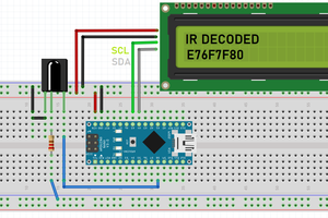
First of all, we will decode our IR remote to get proper data (HEX numbers) Example “F887E790”. Then according to the Hex values, we will program Arduino to make ON/OFF function. And collect the output from digital pins of Arduino. After that we will build a controlling circuit using transistor and optocoupler as a switch. Through this circuit Relay is controlled and we can connect any type of load to ON/OFF.
Remote decoding tutorial: How to decode any IR remote using Arduino.
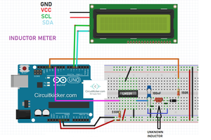
Breadboard schematics:

Components required:
1) SPDT relay x3
2) BC547 transistor x3
3) PC817 optocoupler x3
4) Atmega328p or Arduino
5) Crystal 16Mhz x1
6) 1k Resistor x 9
7) 10k resistor x1
8) 22pf capacitor x2
9) 100nf capacitor x1
10) Screw terminals x3
11) 5mm red led x3
12) 100ohm resistor x1
13) General purpose PCB x1
14) 9v battery
15) 1N4007 Diode x3
16) TSOP 1738- IR receiver x1
Circuit diagram:

Circuit making:
We will make this circuit in sections, so that circuit can be more understandable to us. First mount all the relays and screw terminals corresponding to it as shown in the PCB.

Taking idea from circuit diagram and PCB, mount all other components transistor, optocoupler, resistors, diodes and led. Using the same idea, we can increase relay channels from one to three and even more. Maximum relay channels that can be supported using this method is 12.
After controlling circuit, we will build microcontroller and power supply section, here we are using Atmega328p- 8bit Arduino’s popular microcontroller. This is more than enough for this type of project, Atmega328p works on 16Mhz crystal and also have EEPROM feature. EEPROM is helpful to keep last state of relays in mind when power goes off or disconnected.
In last we will connect TSOP-1738 and read Hex data values using Arduino digital input pin. Code is exactly turn ON/OFF the corresponding relay as stated in code.

A 9volt battery is enough to power the circuit properly. Our microcontroller and relays work on 5volts, that’s why using 9volt battery, a 5volt regulator (7805) is mandatory to use.
While working with general purpose PCB board, we should use pointed tip soldering iron, 63/37 solder wire and try to build this circuit using bridge soldering method.

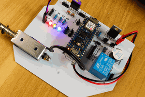
Circuit PCB:
Download all the required files, circuit diagram, schematics, Code and PCB Gerber files from here

Circuit details:
Basically, we are dividing the circuit concept of this projects in some steps:
Step1: Decoding the IR remote, to decode any universal IR remote using Arduino just read our other project Article. So that it will be clearer to you. Follow this link here.
Step2: Make the circuit using schematics given above or you may use Our PCB Gerber file to directly order this project from JLCPCB.
Step3: Upload the given code in atmega328p microcontroller.
PCB single layer layout:

Working:
Every button in IR remote has different hex number data, if we want to turn ON/OFF a device, we need two buttons of IR remote. One to switch ON and other one to switch OFF the same device.
Similarly, here we are making 3 channel relay controllers, that’s why we need 6 different buttons. Also, when we want to switch ON/OFF all the devices at same time, we need two more buttons. In total our IR remote should have 8 buttons.

When remote release IR hex data, it will be captured at receiver...
Read more »
 Jithin Sanal