0%
0%
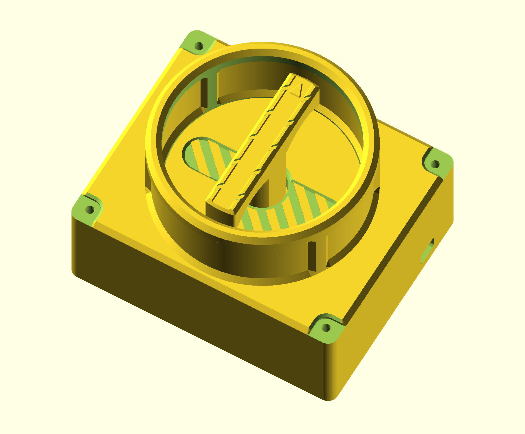
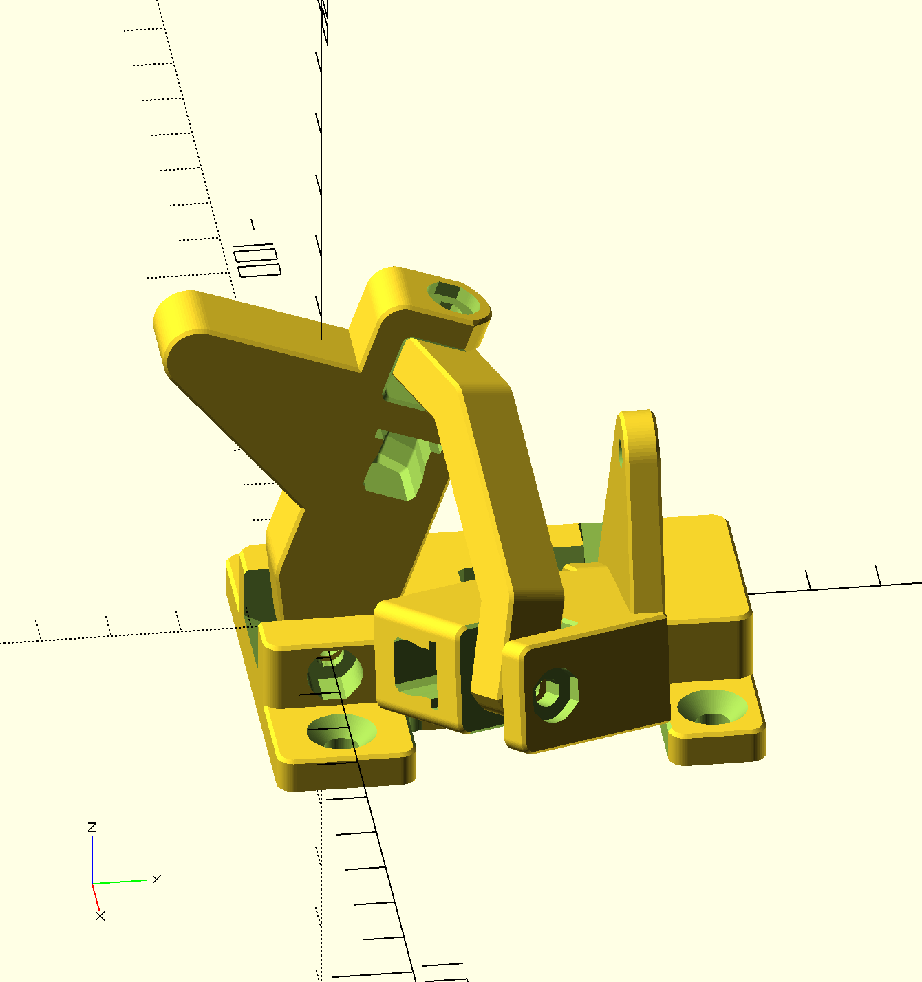
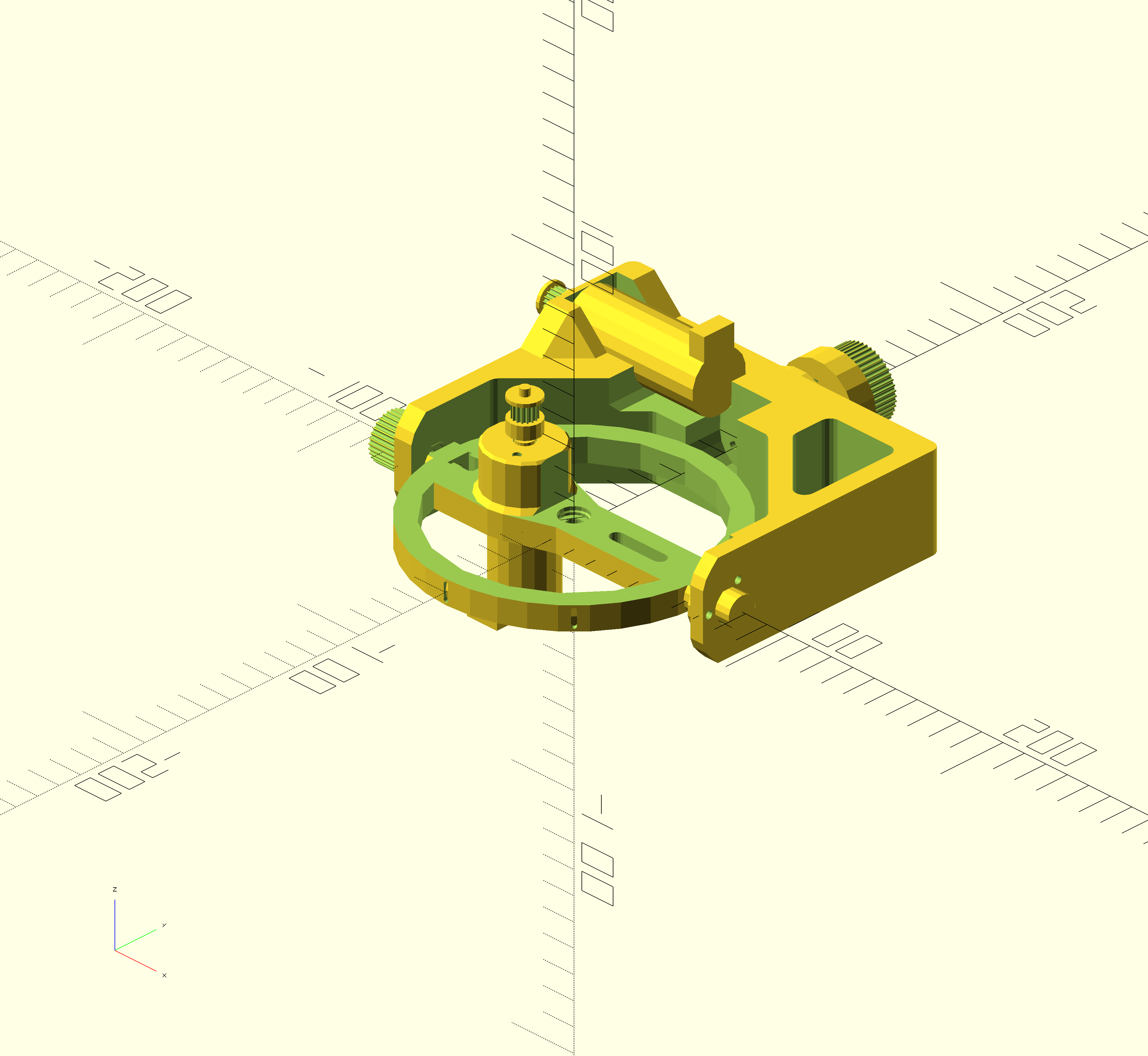
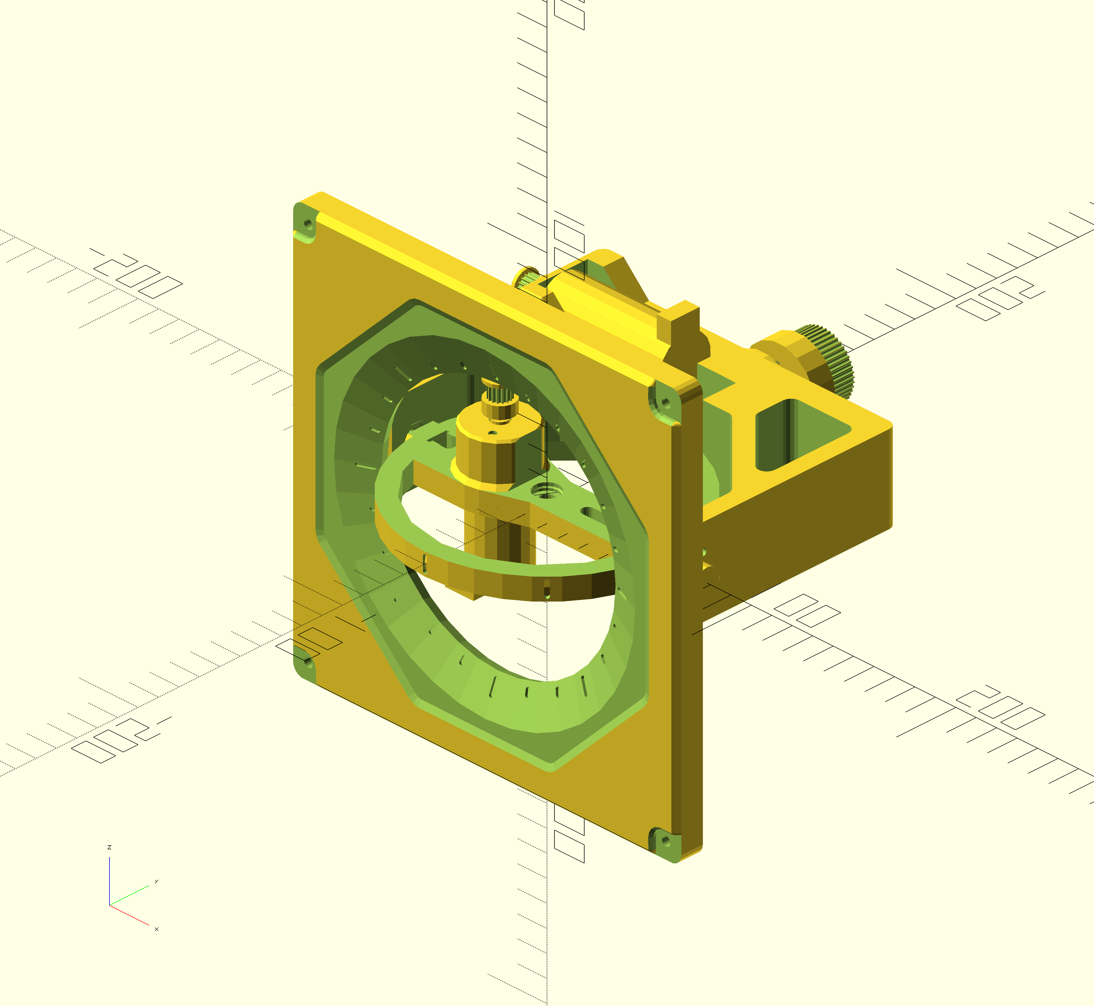
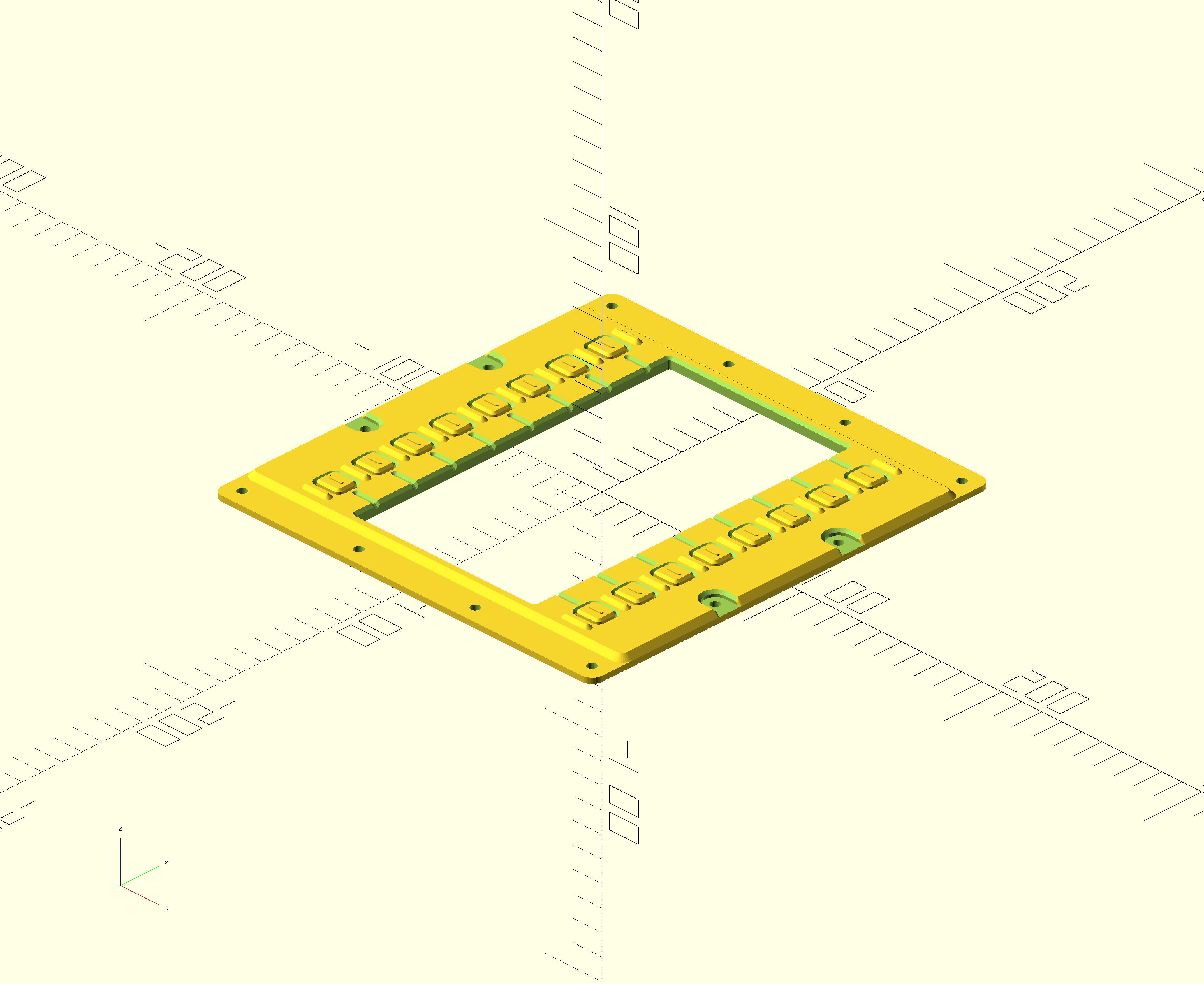
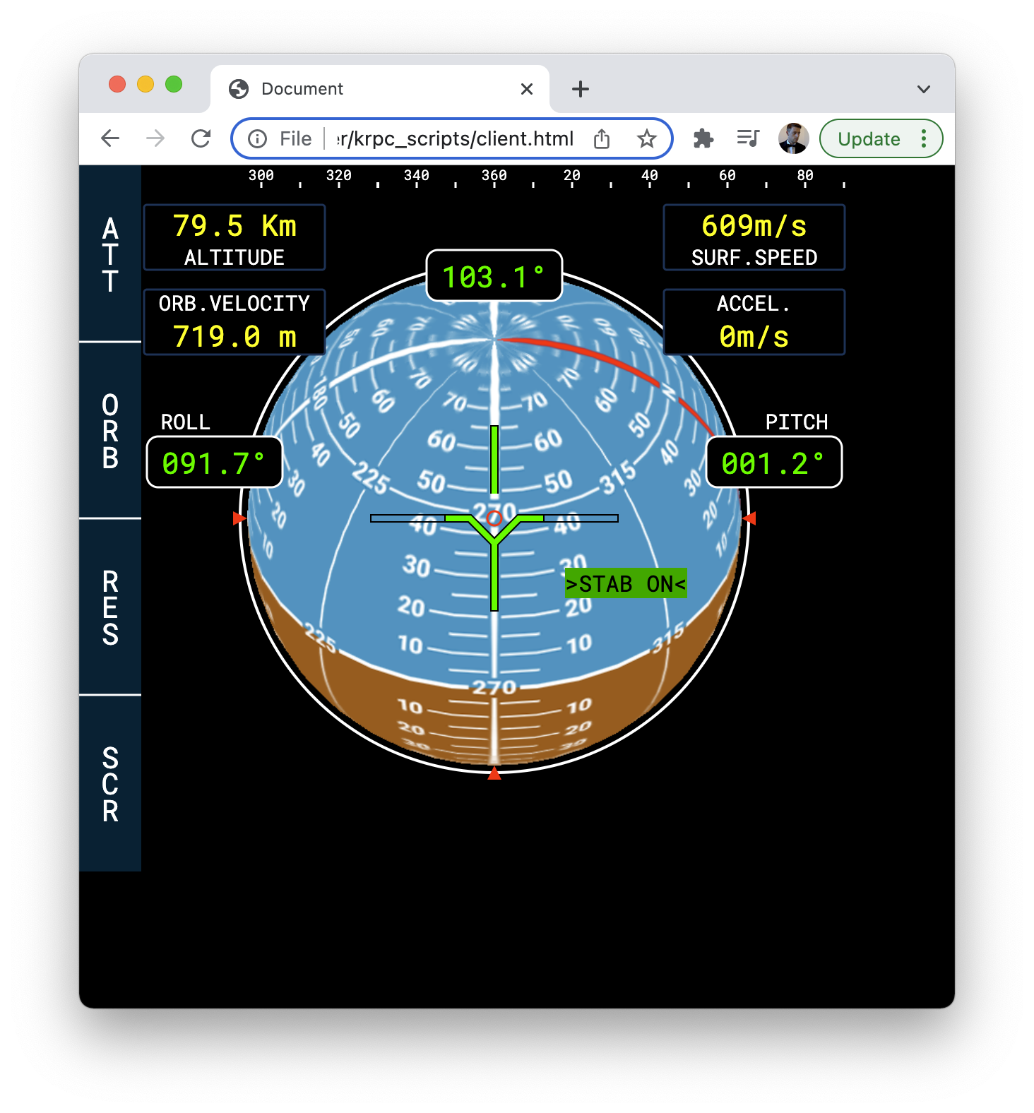
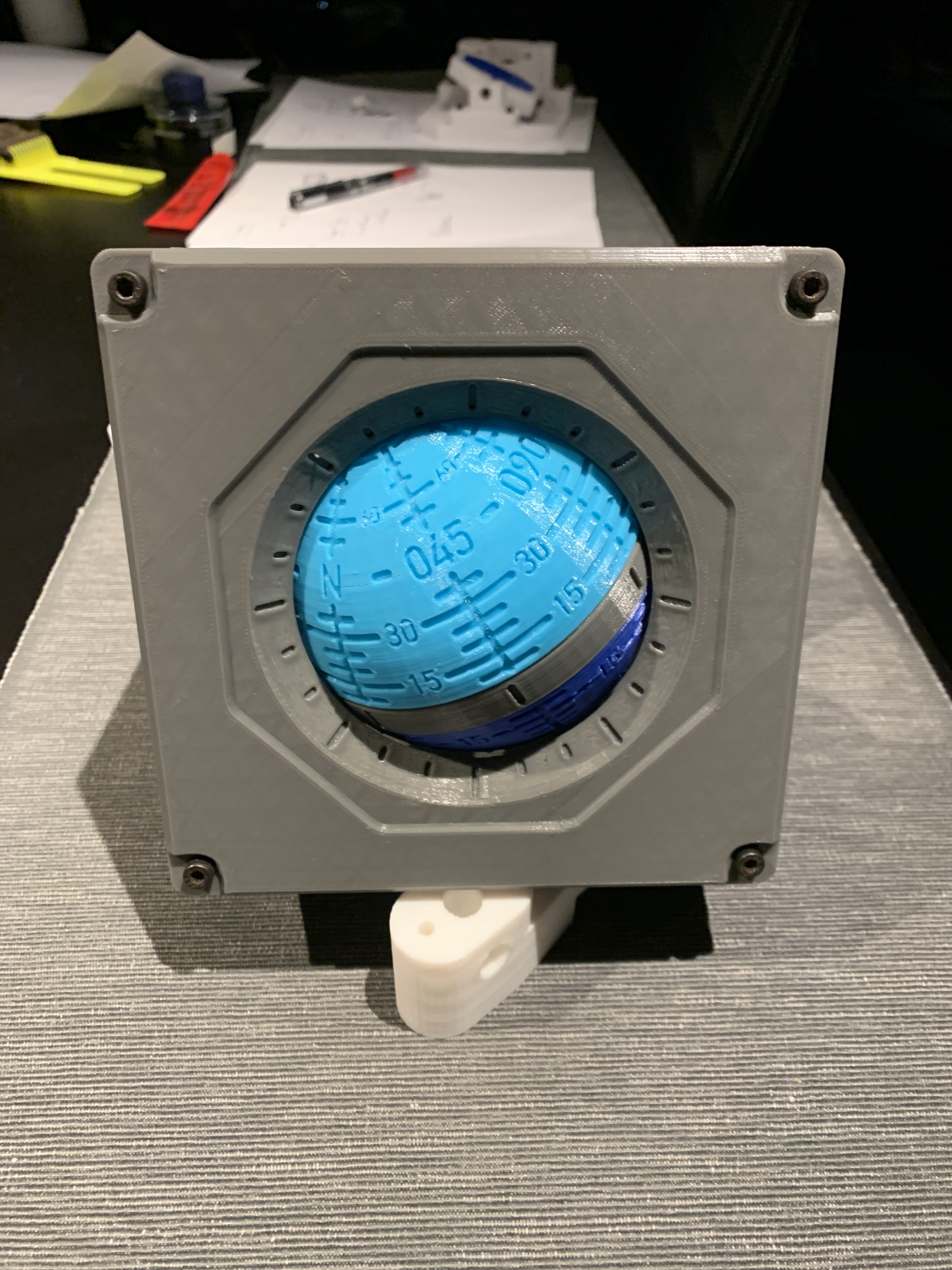
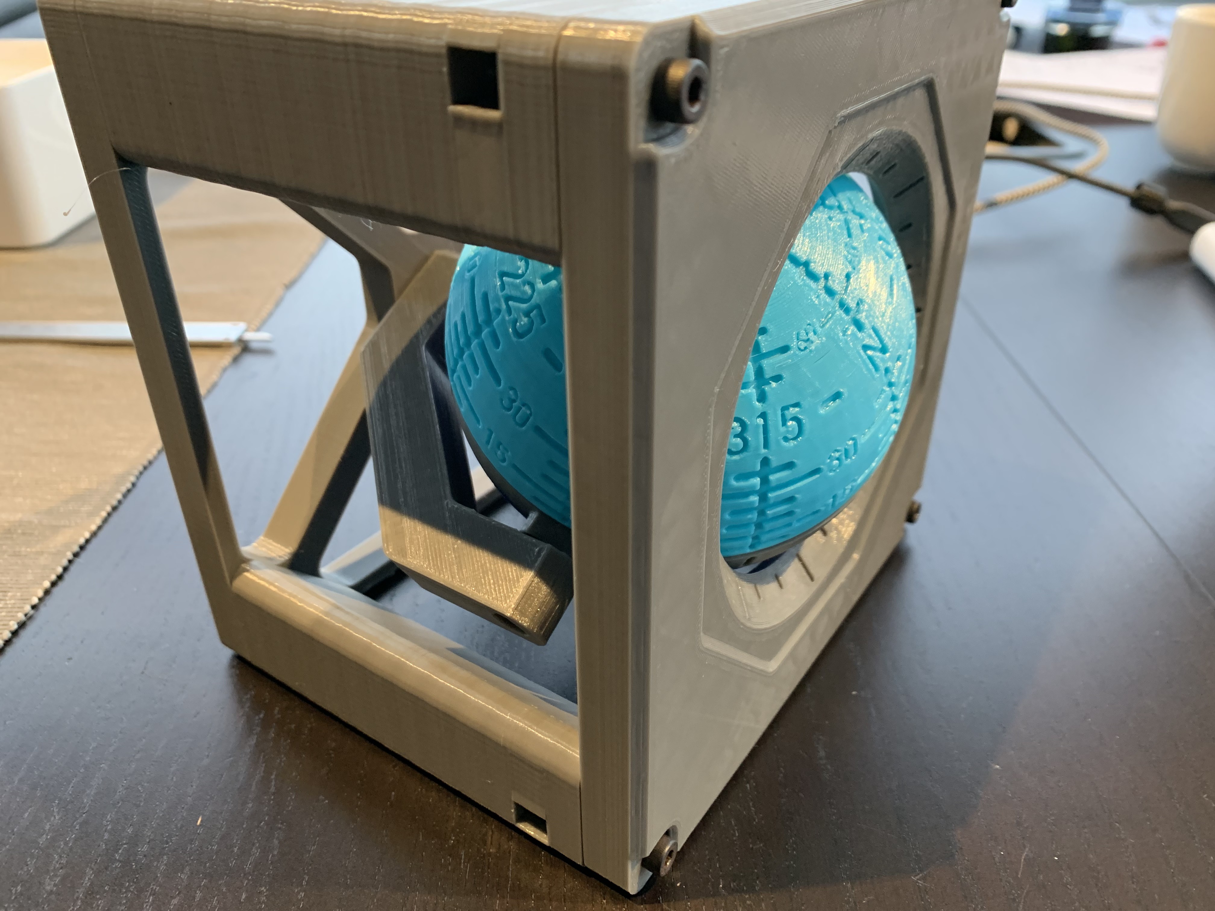
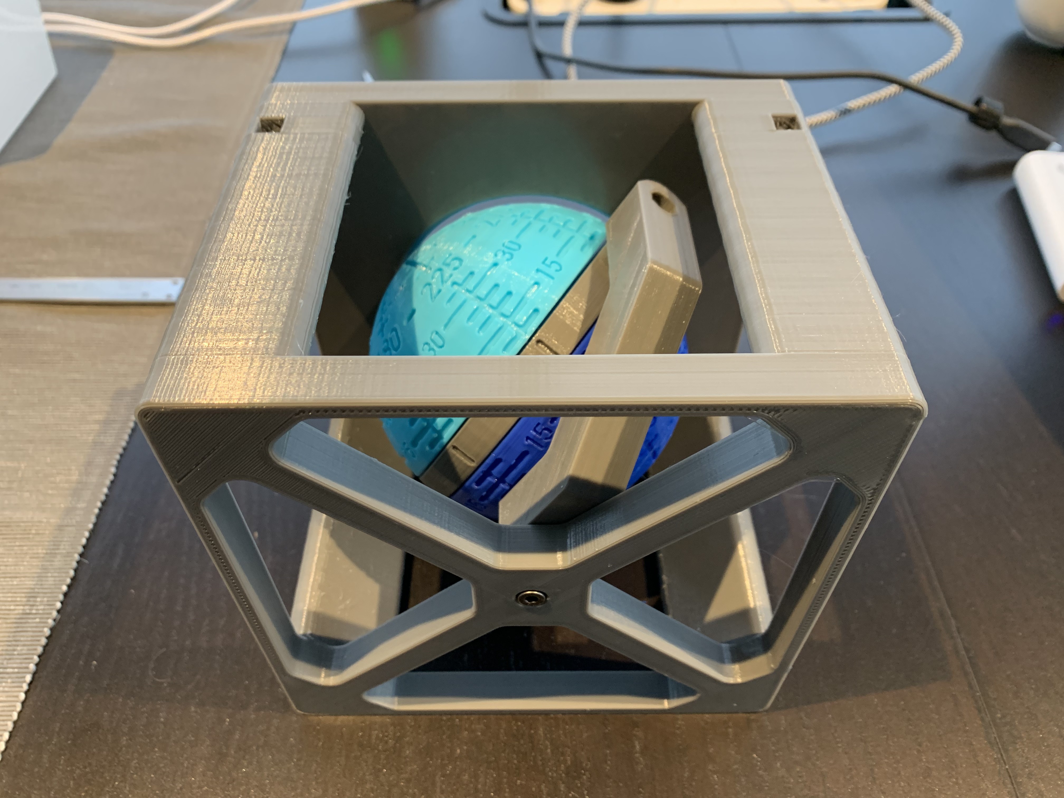
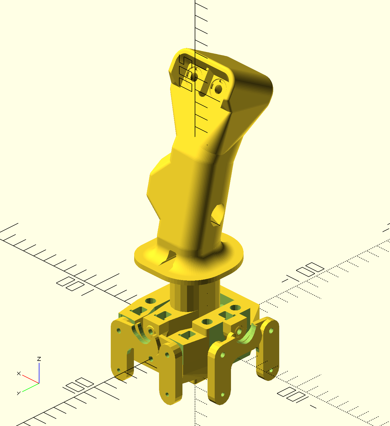
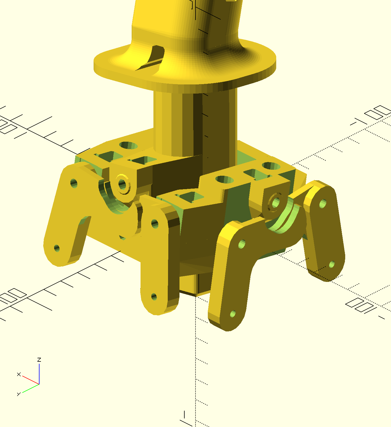
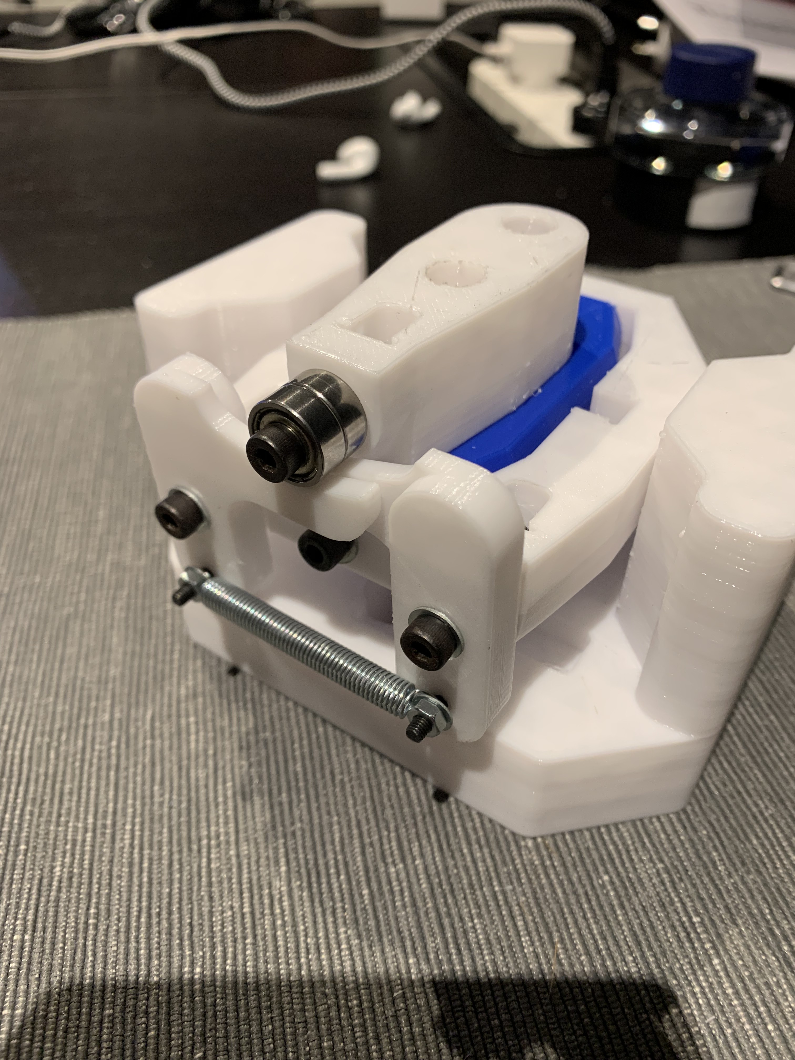
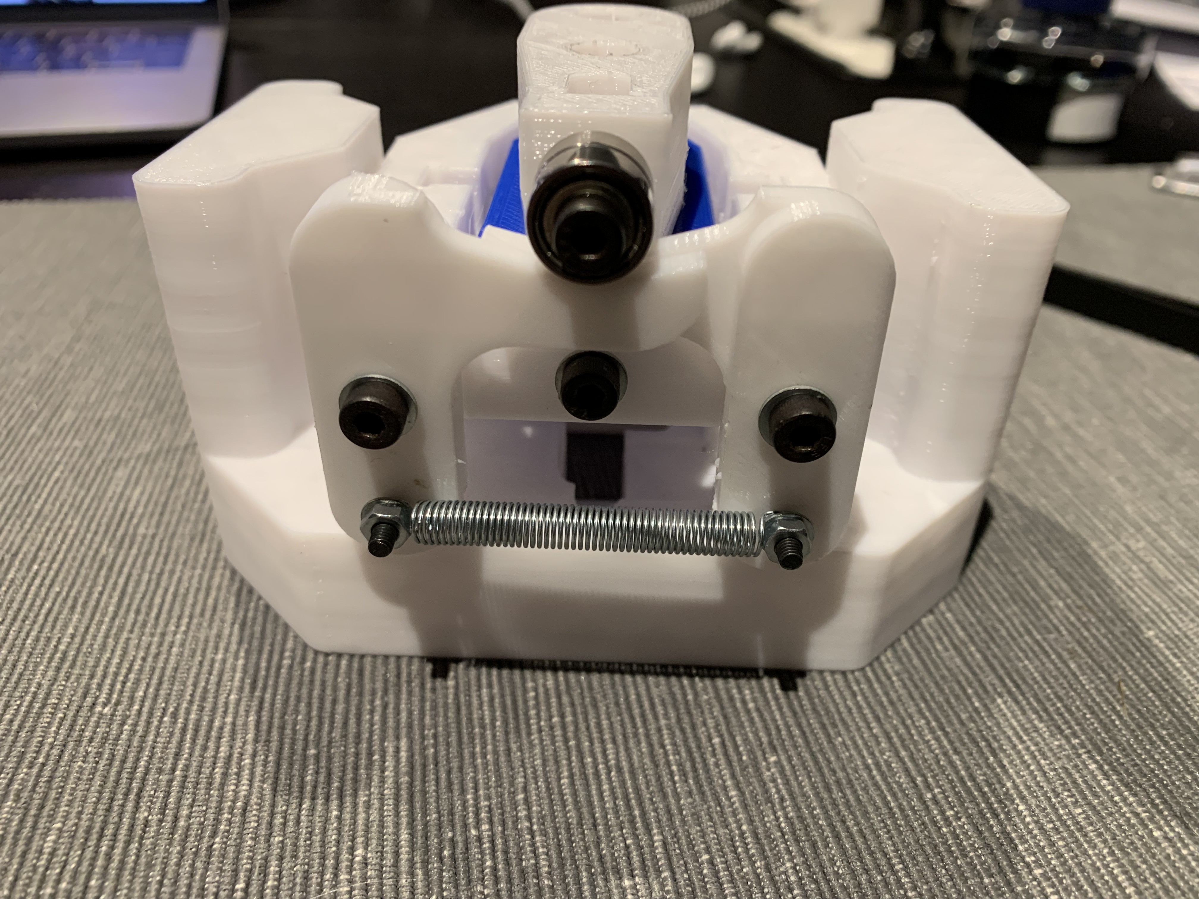
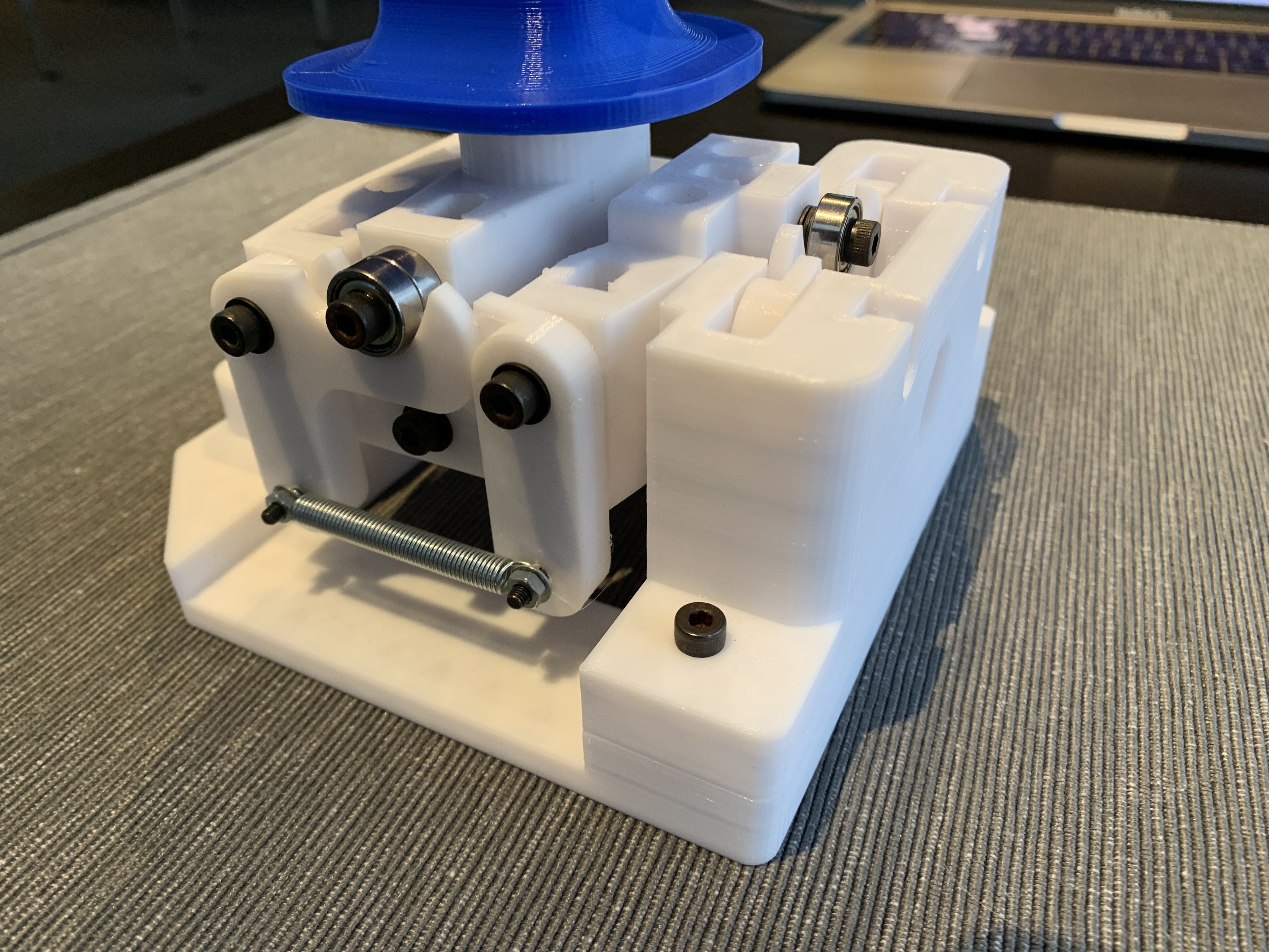
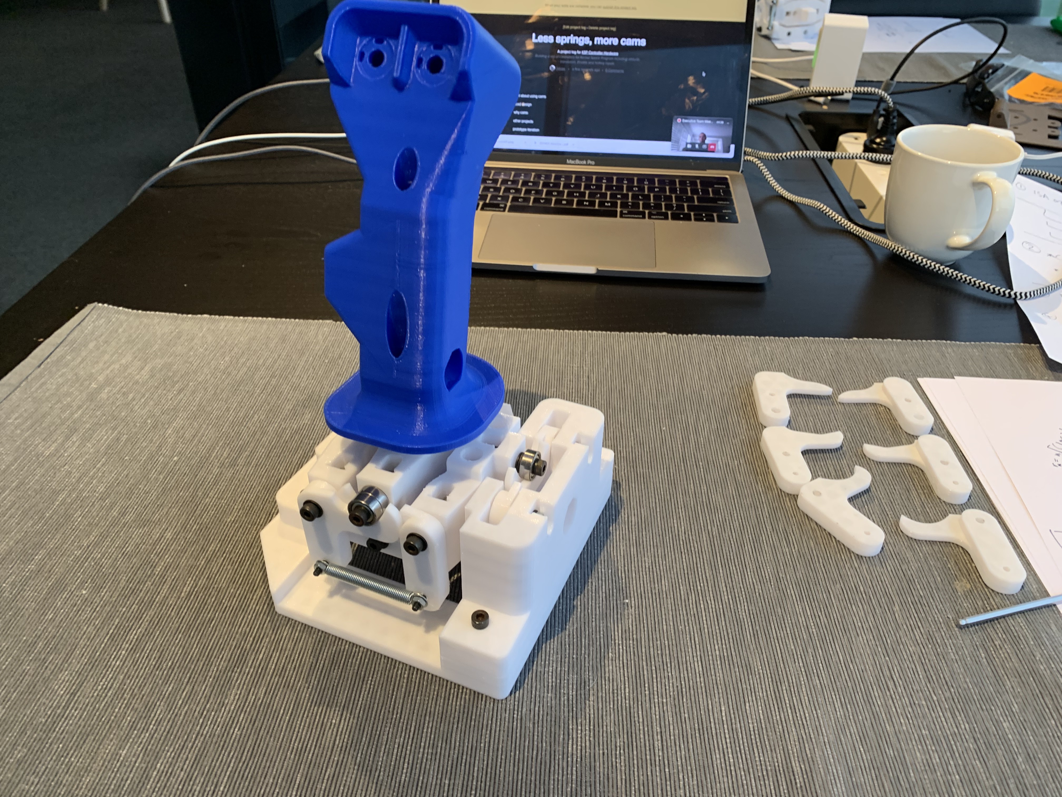
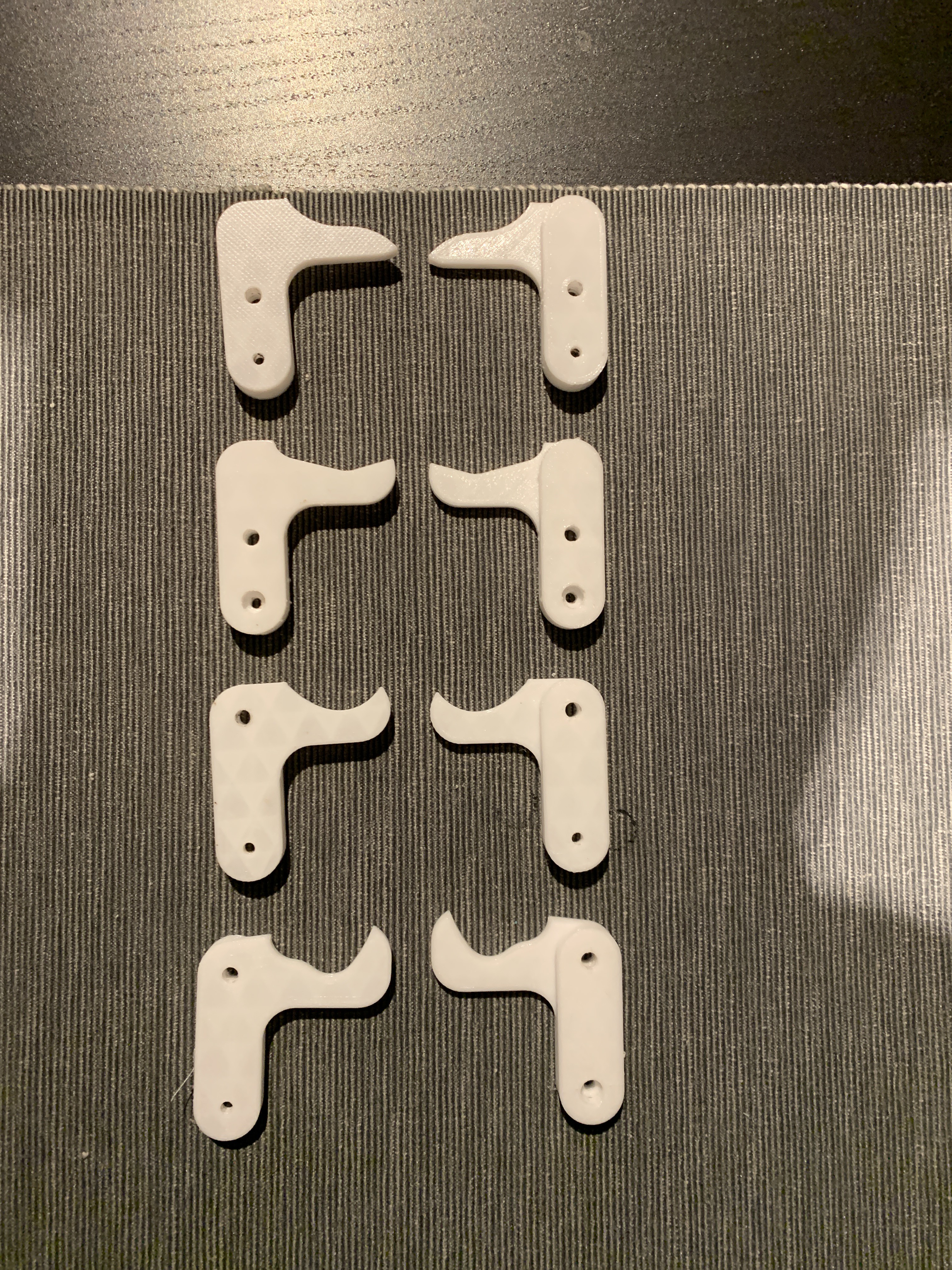
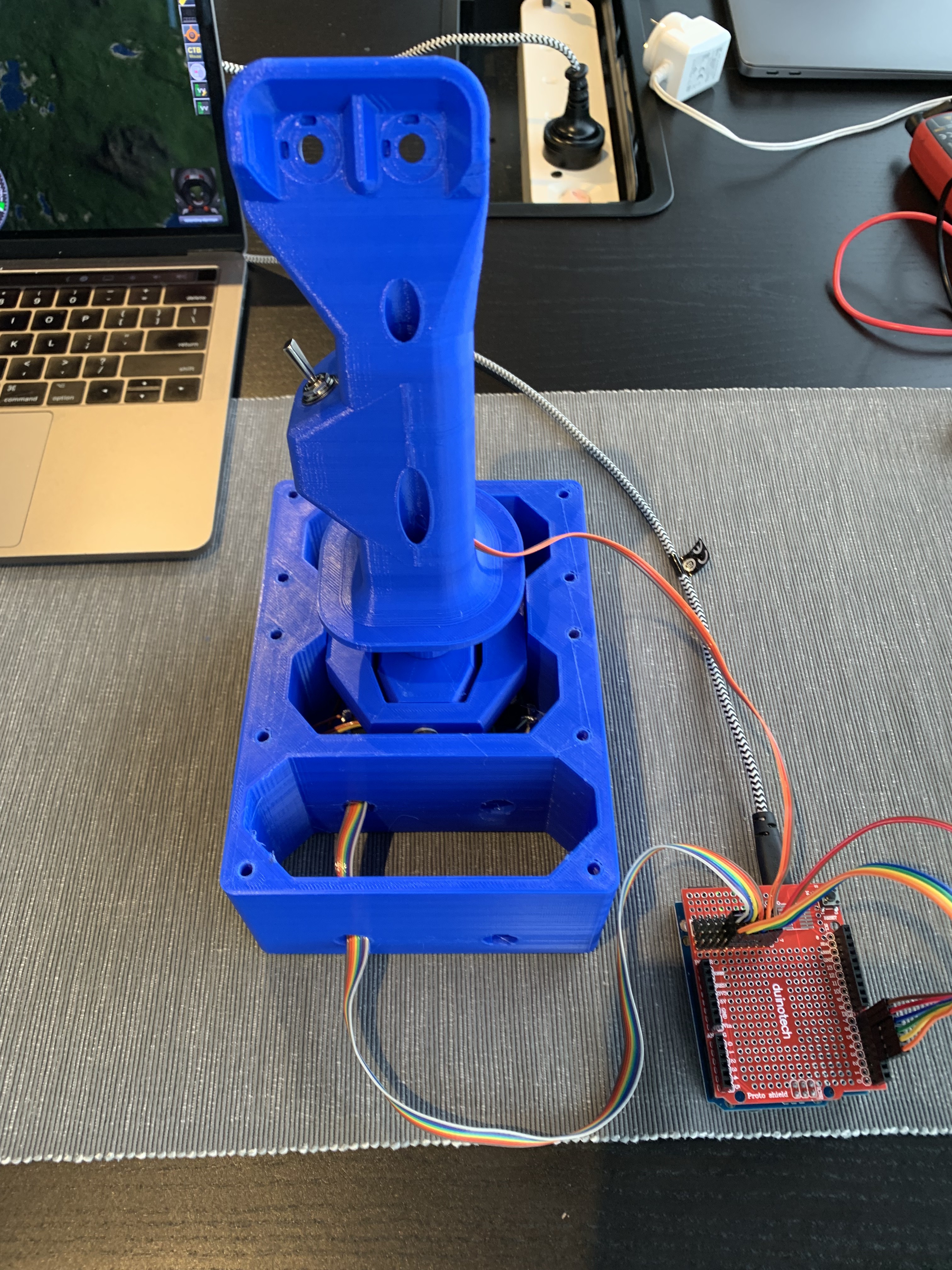
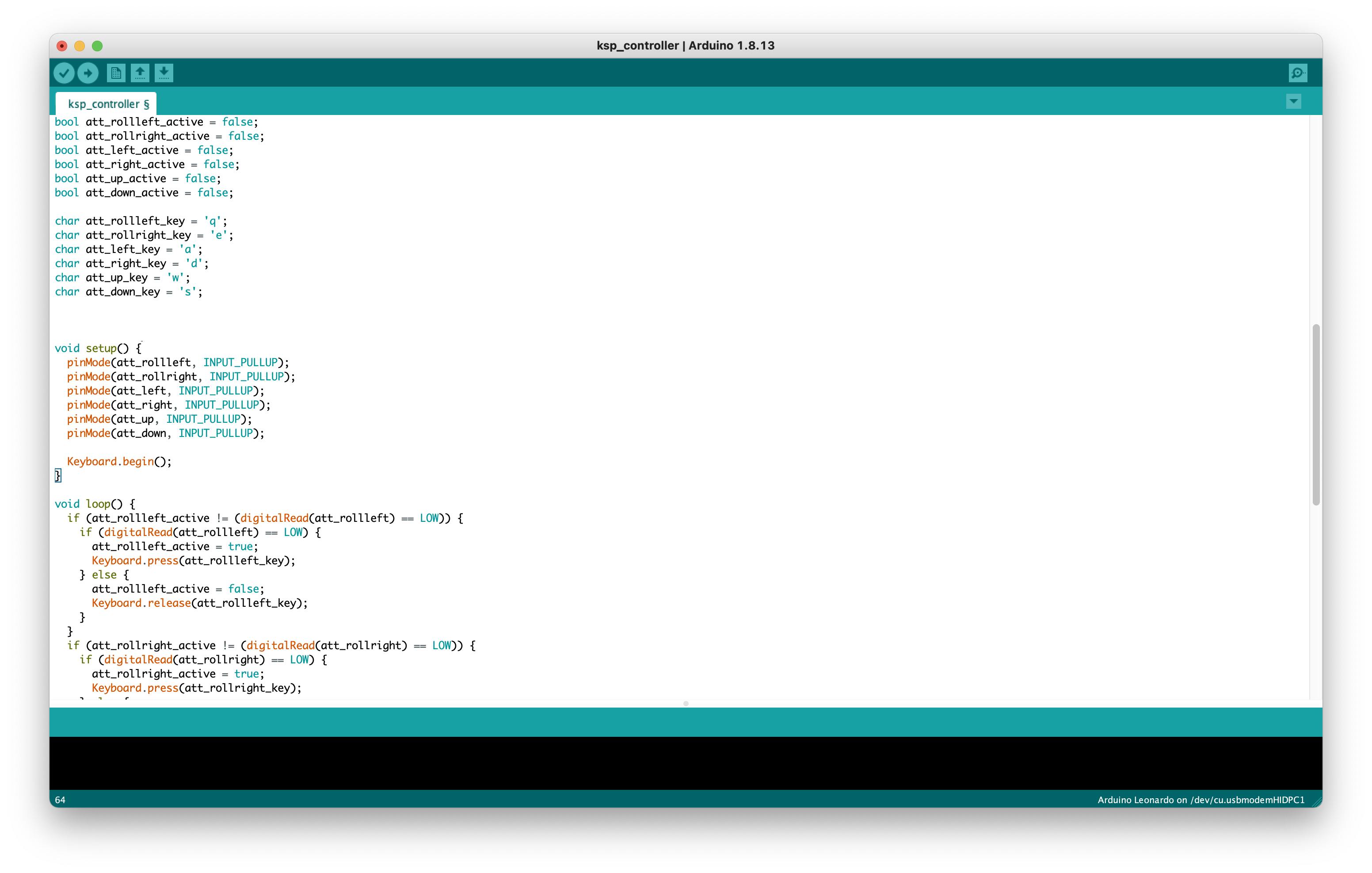
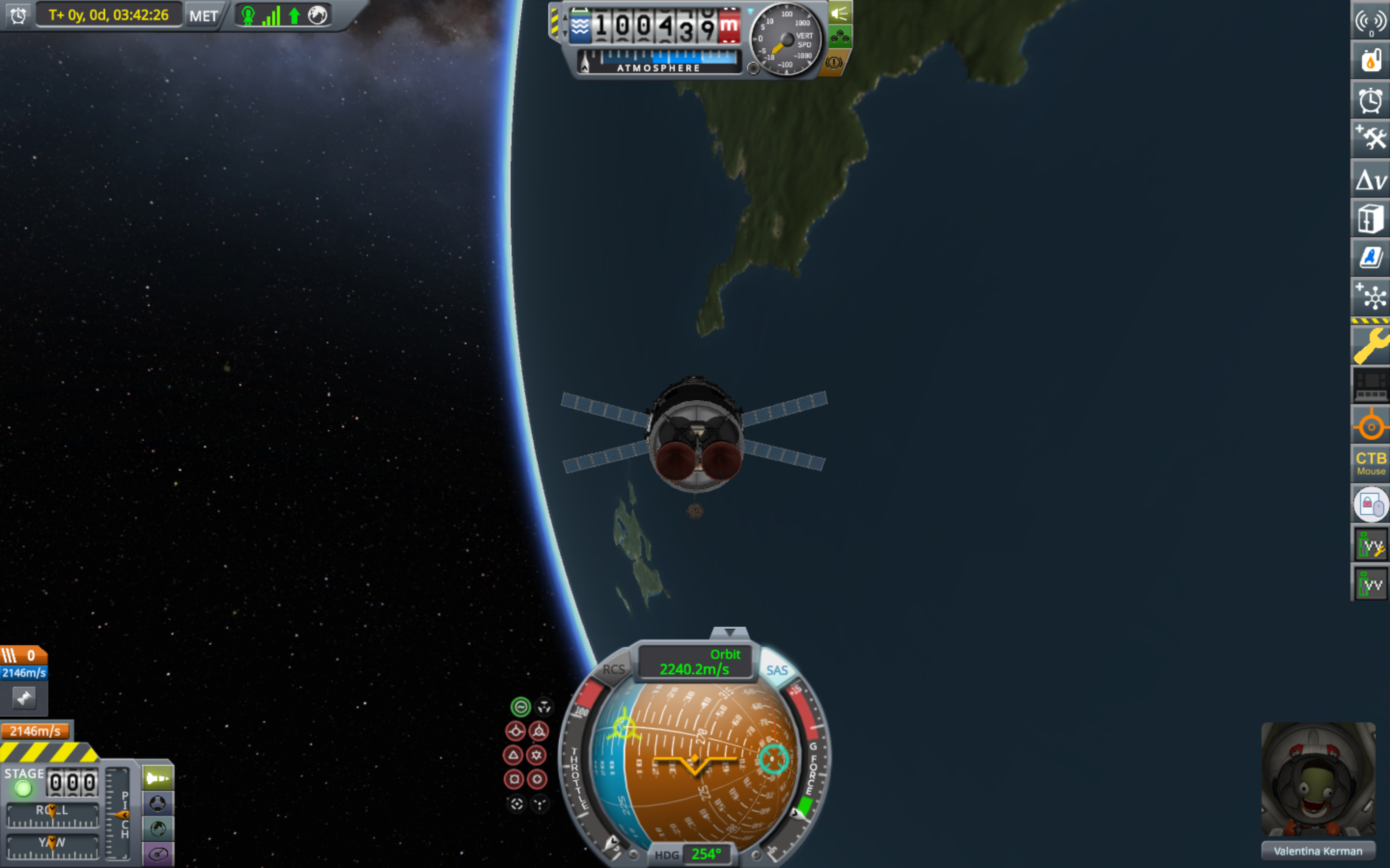
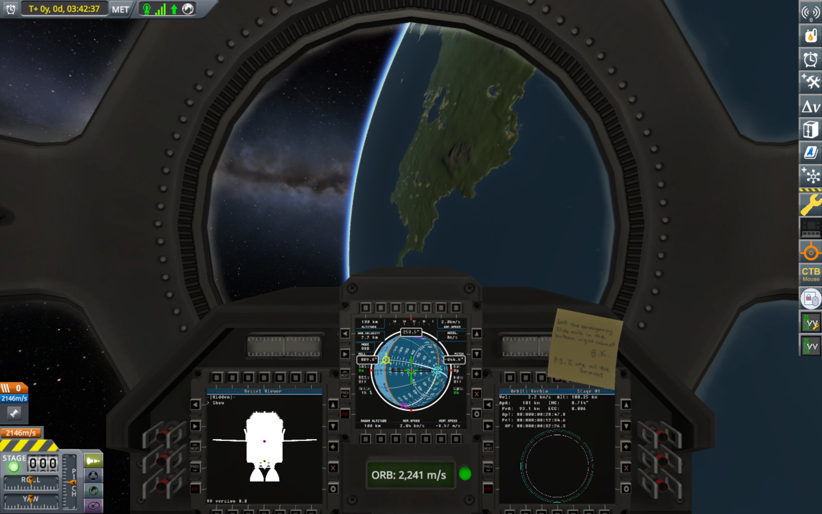
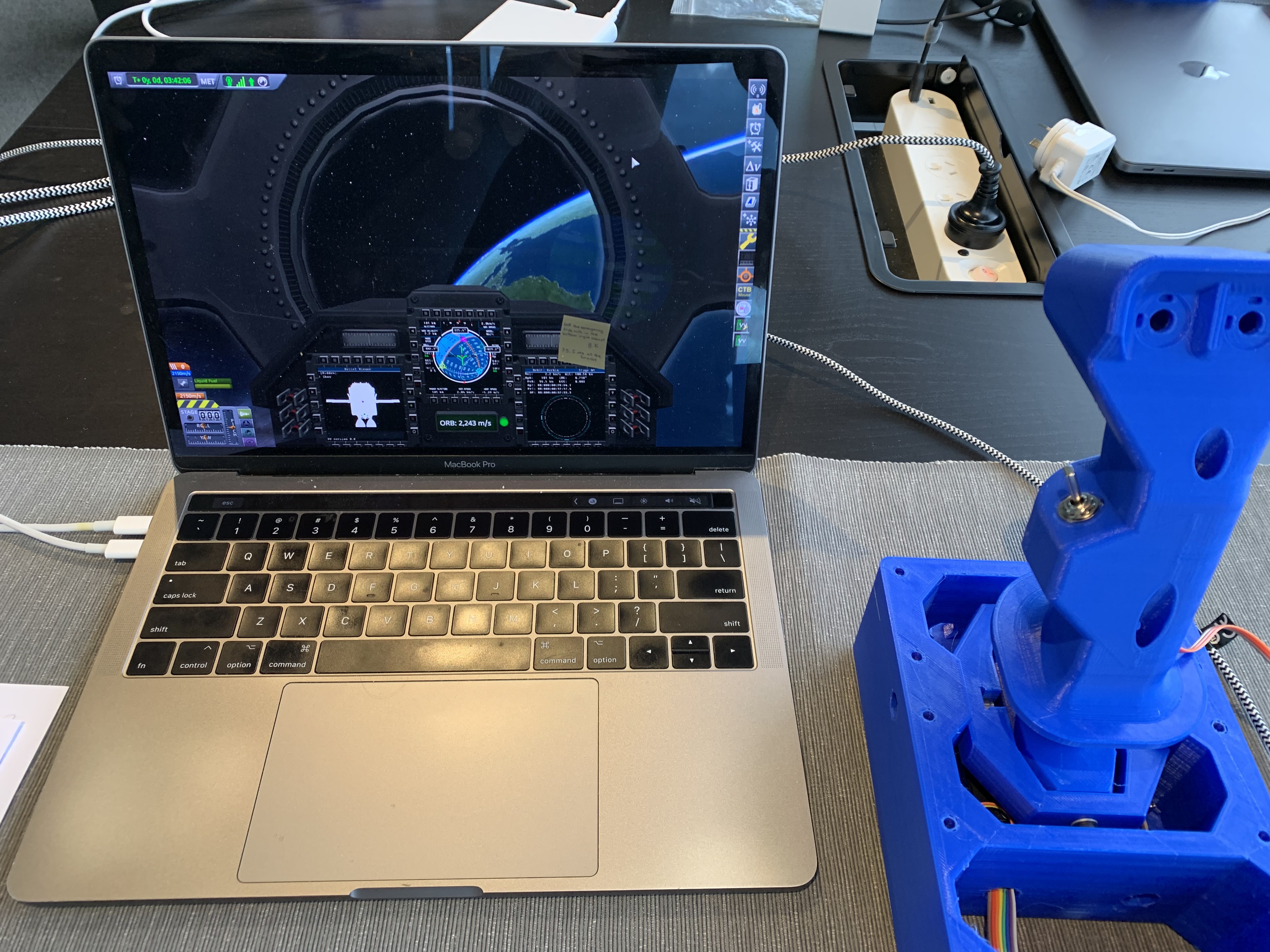
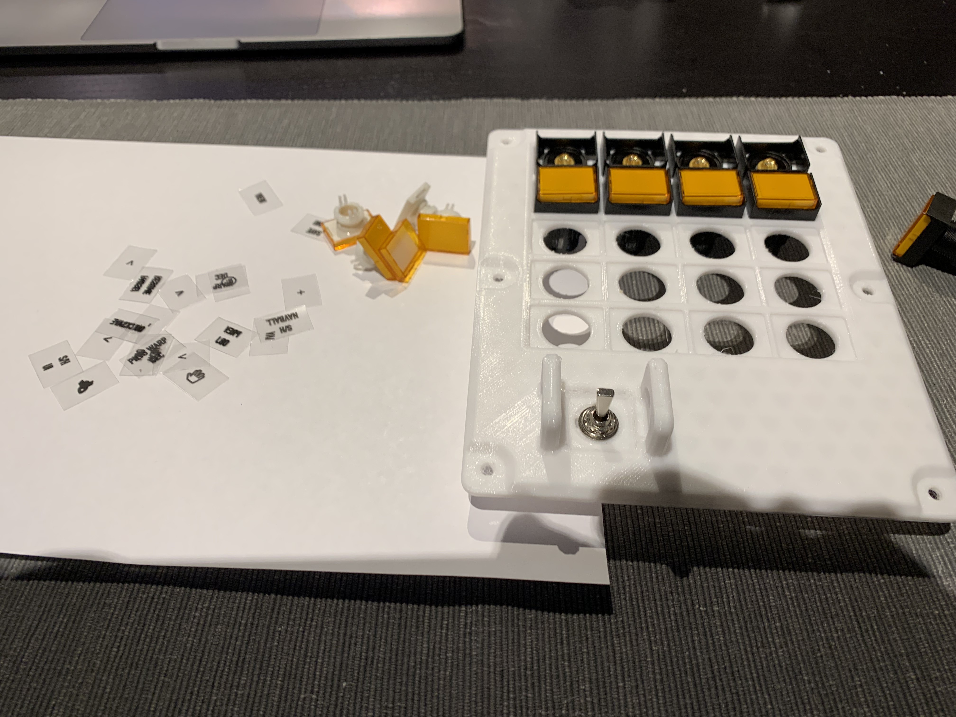
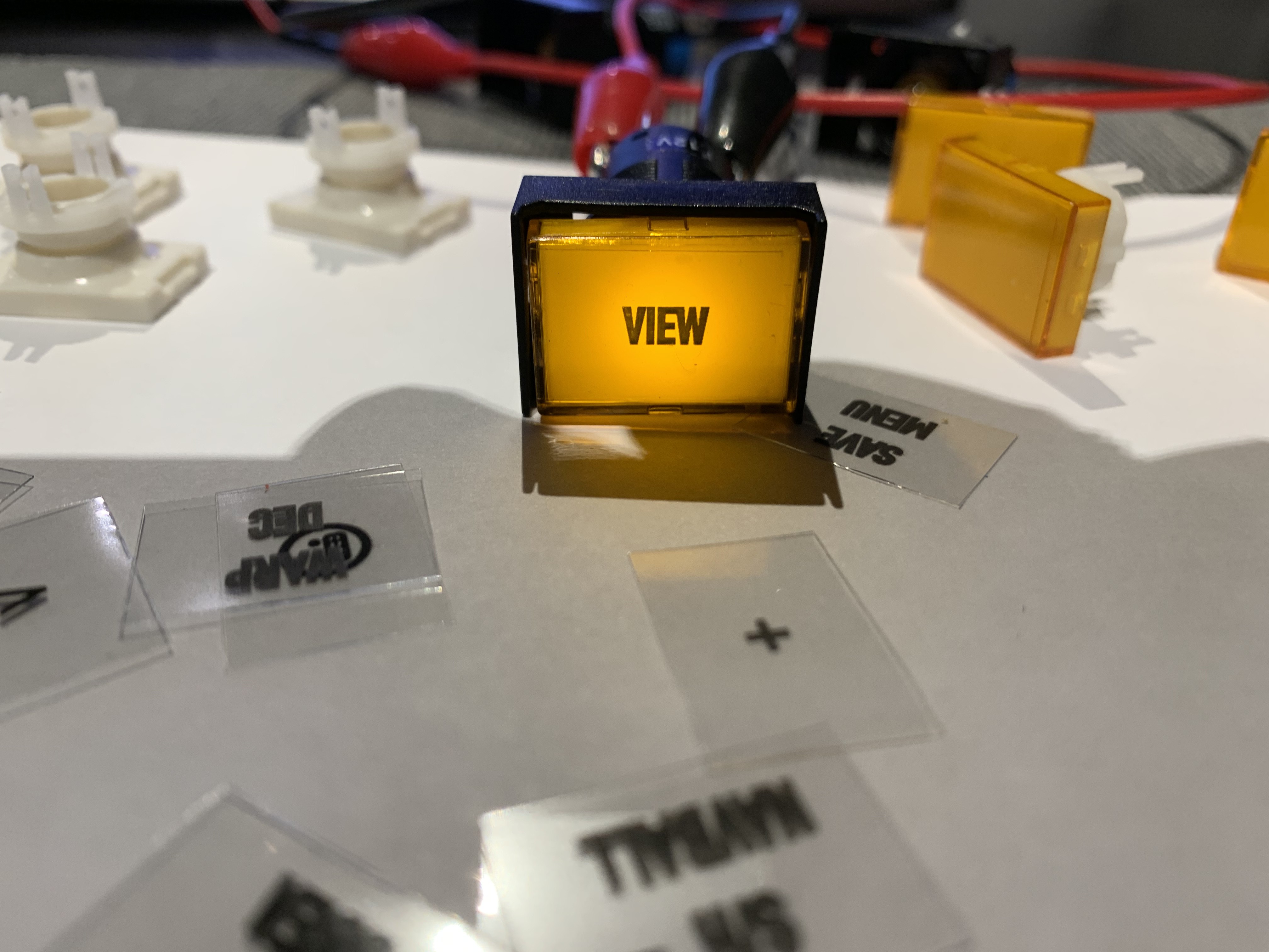
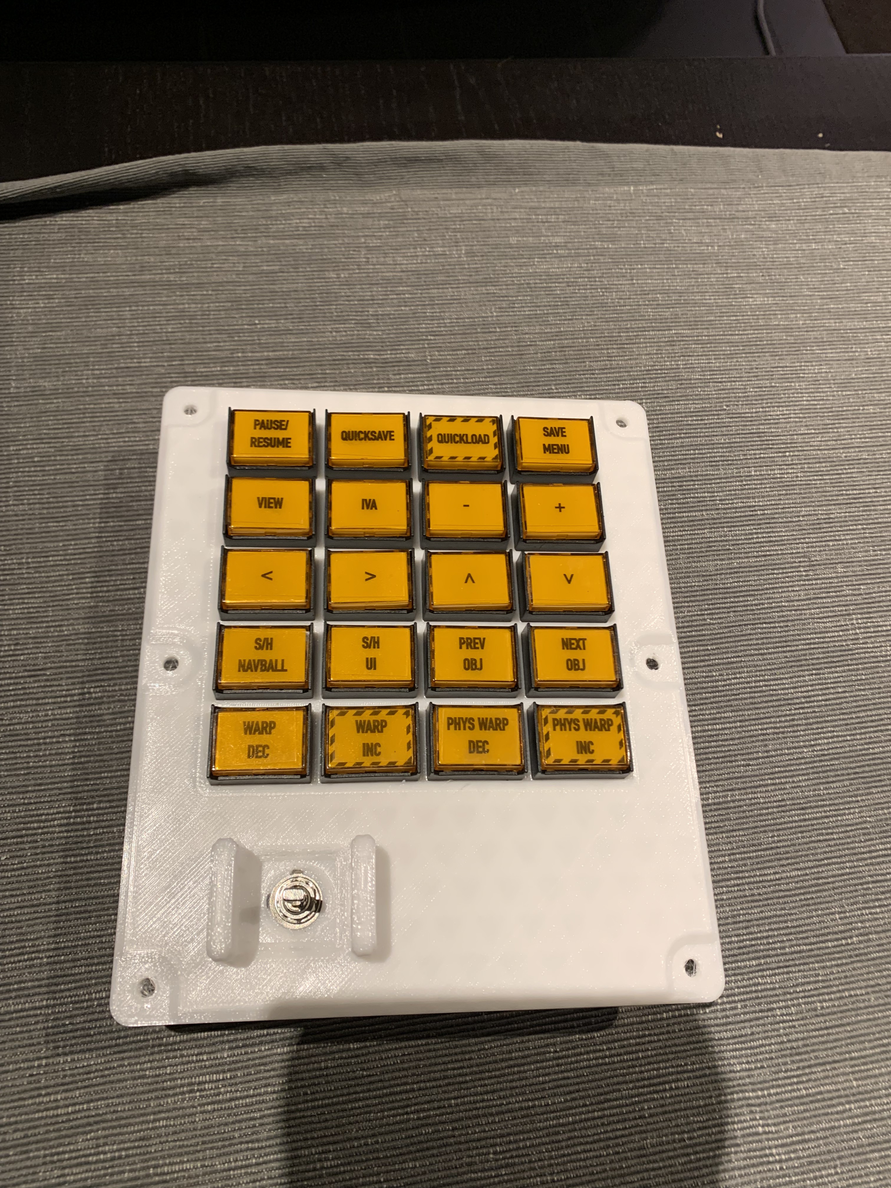
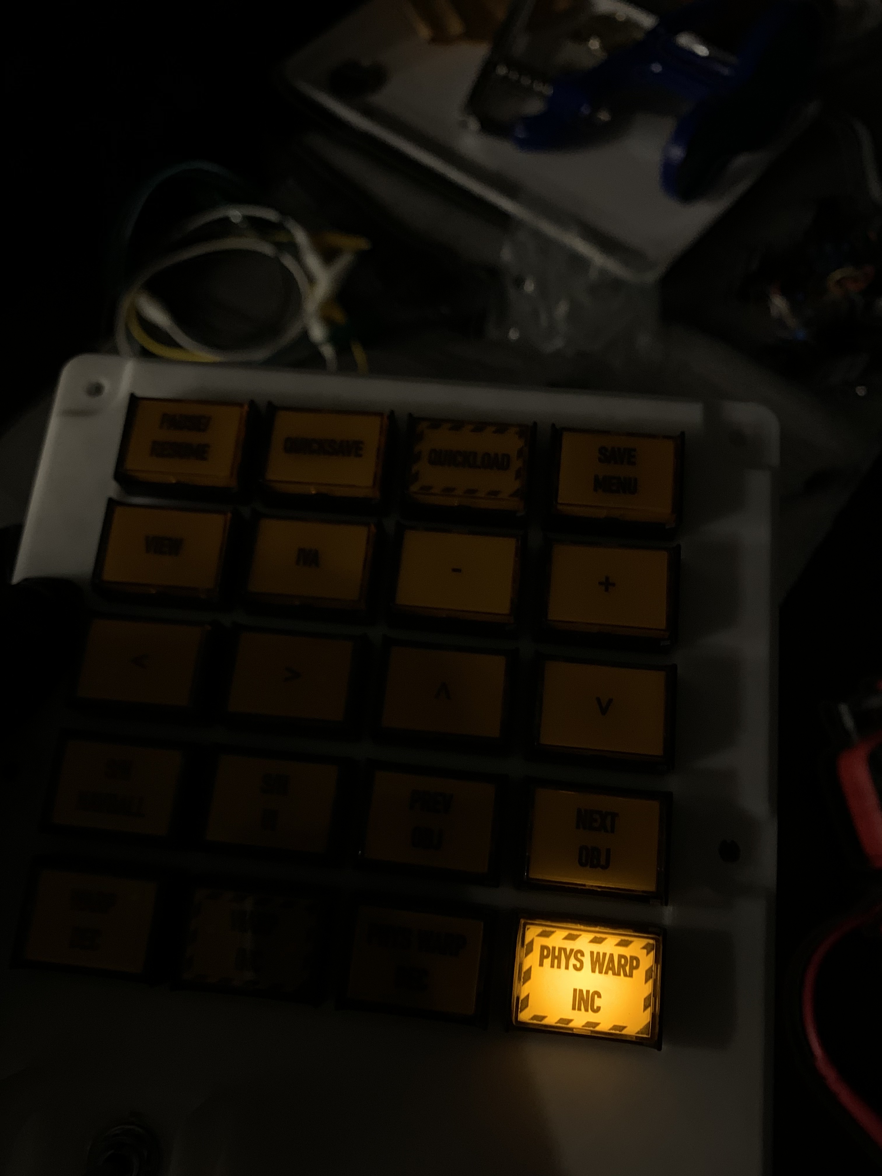
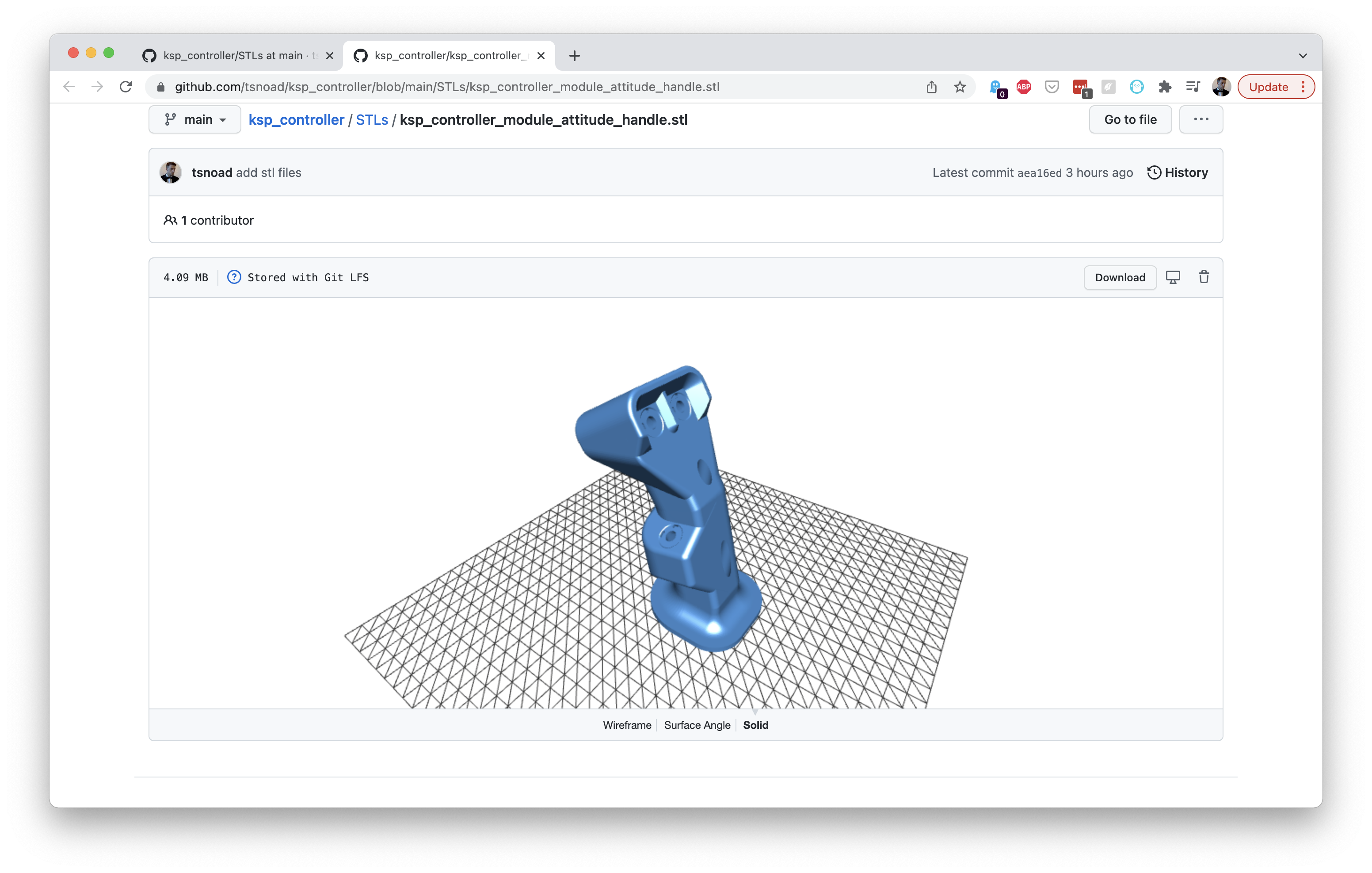
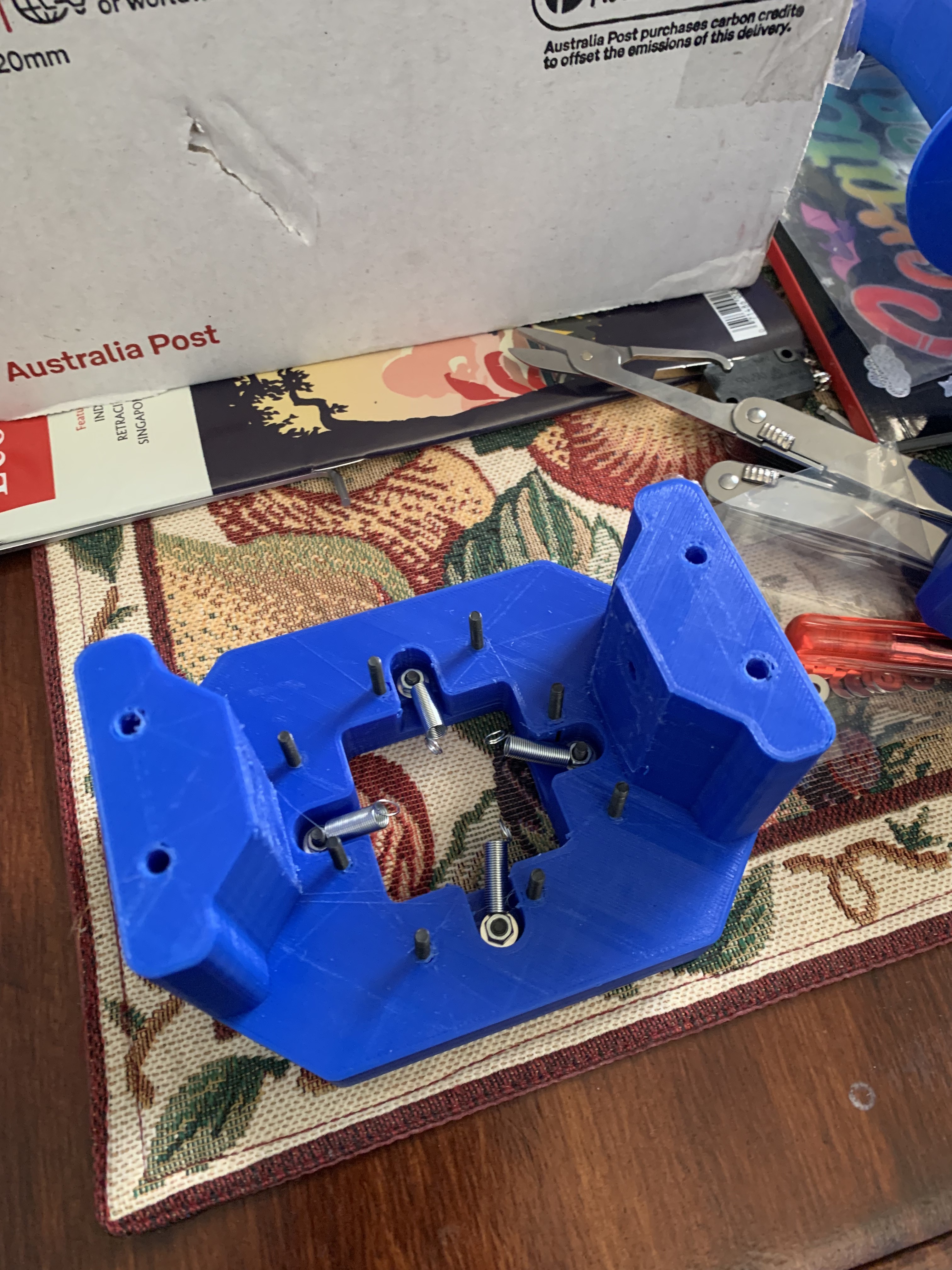
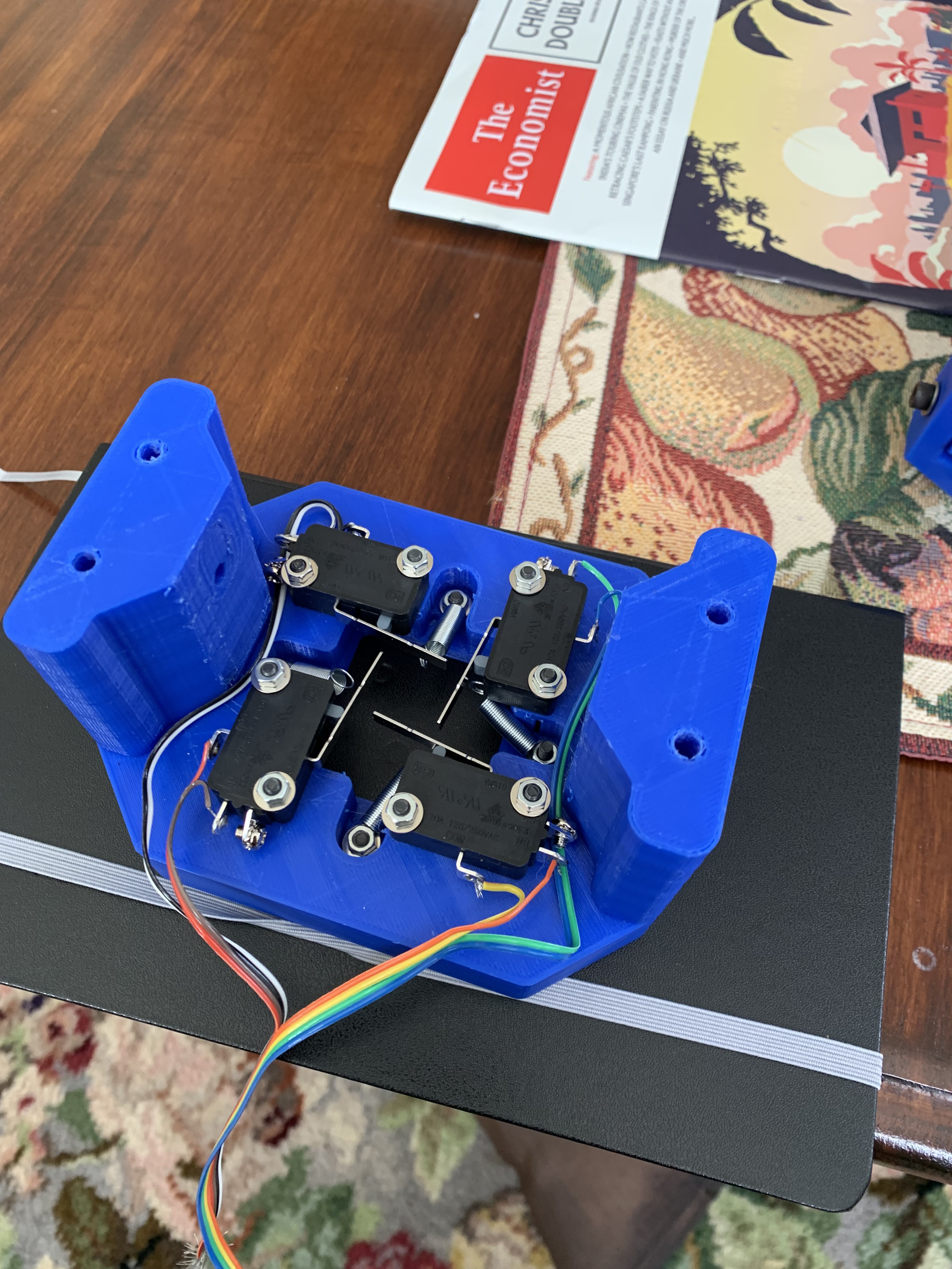
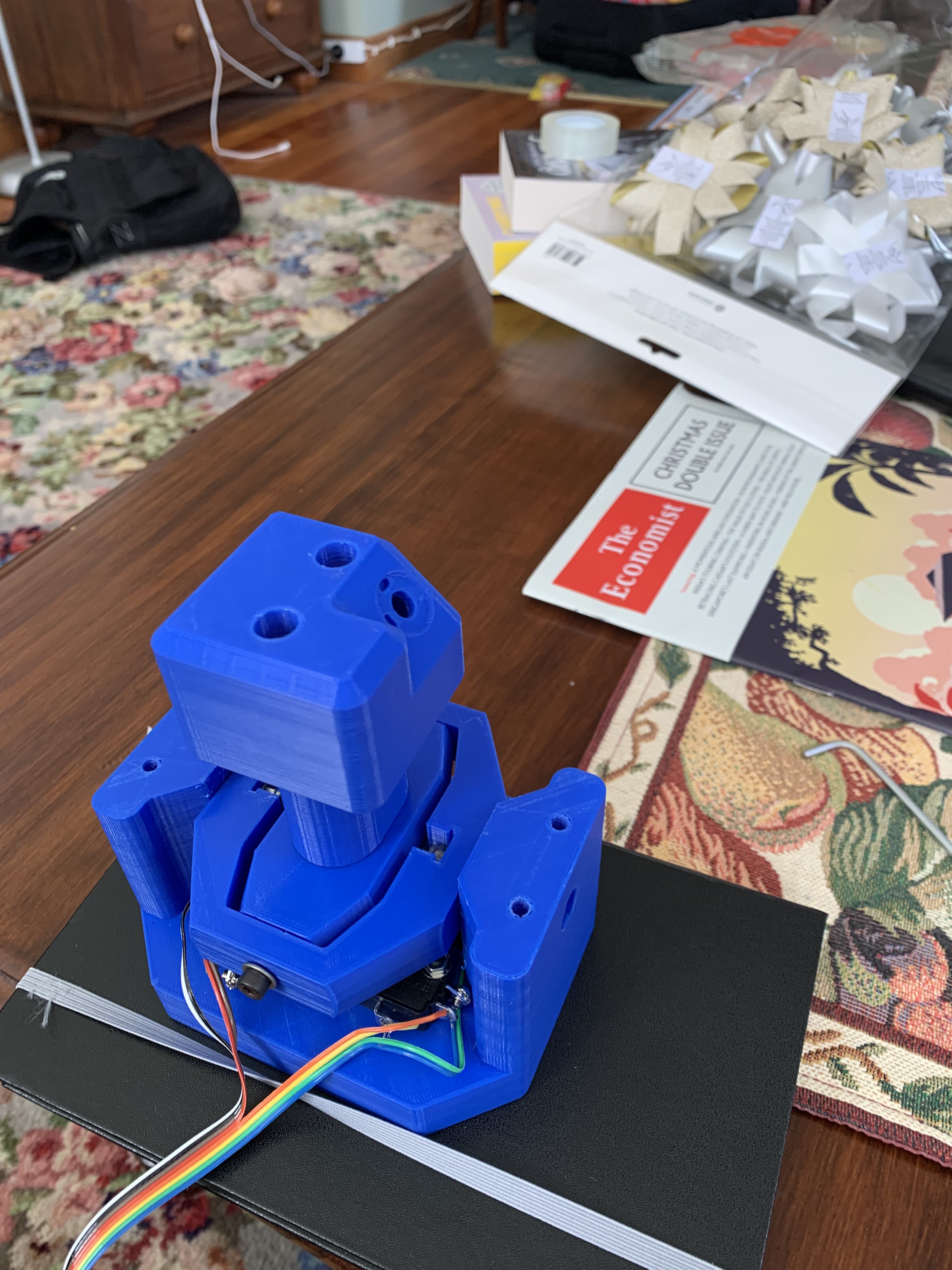
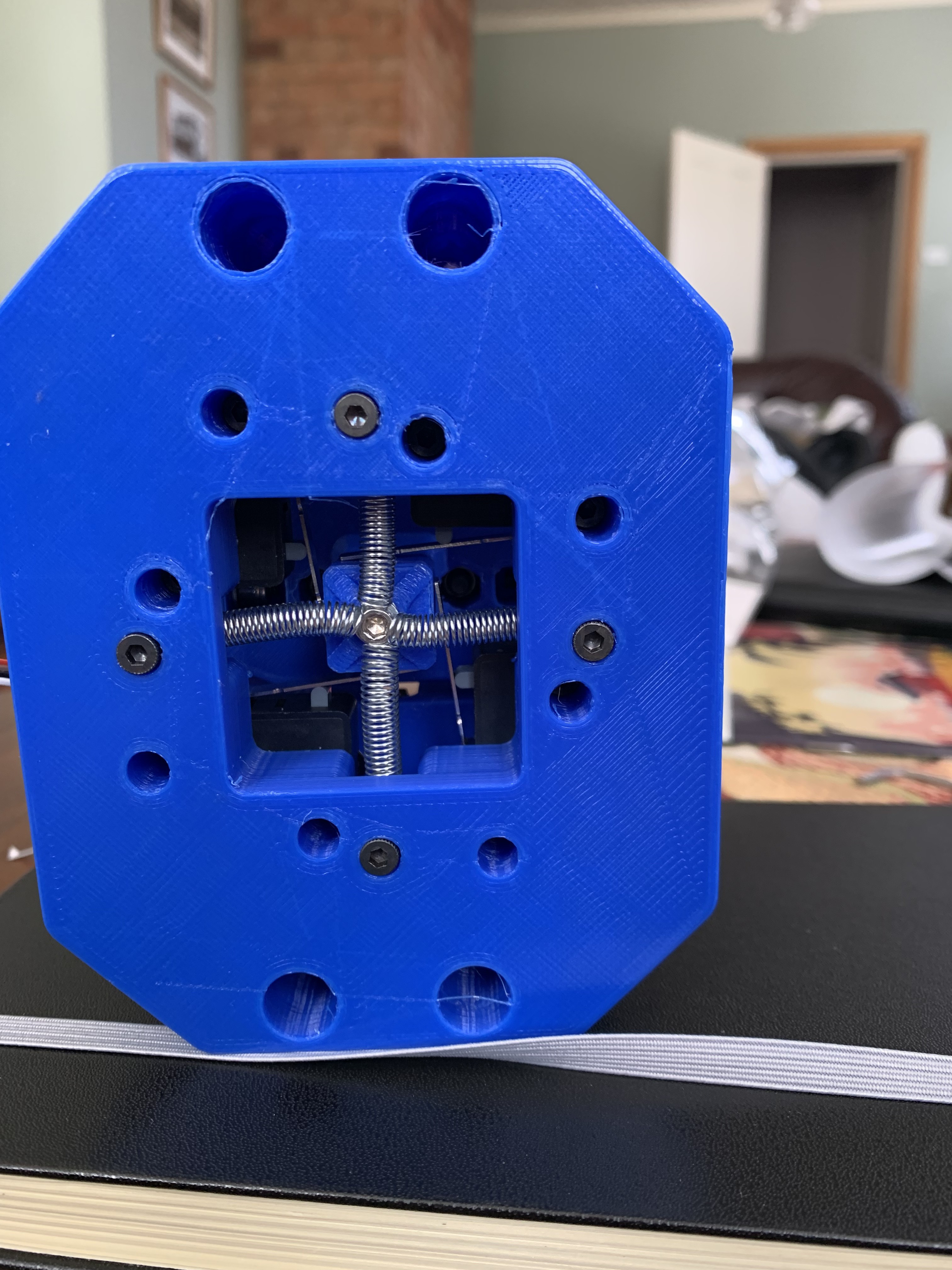
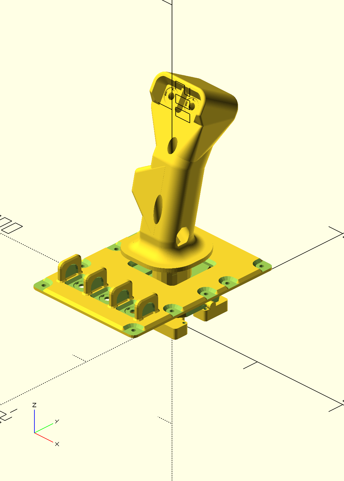
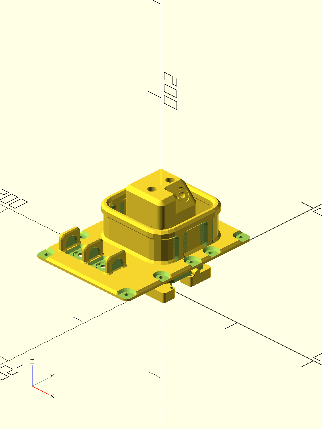
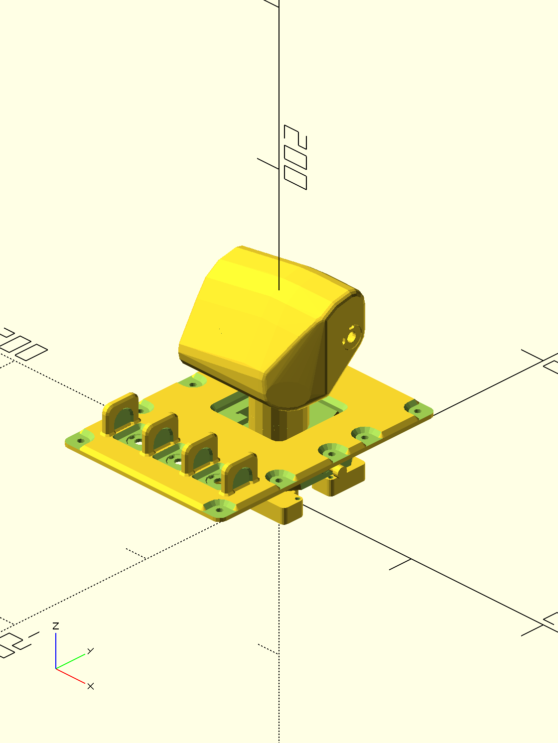
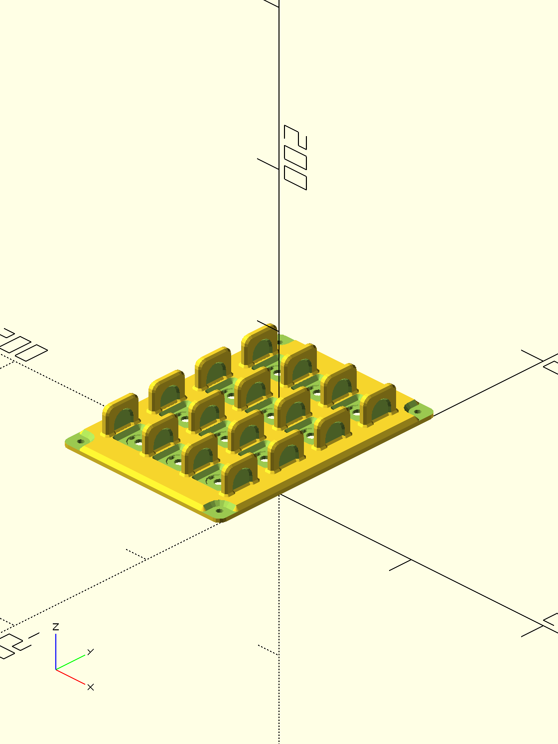
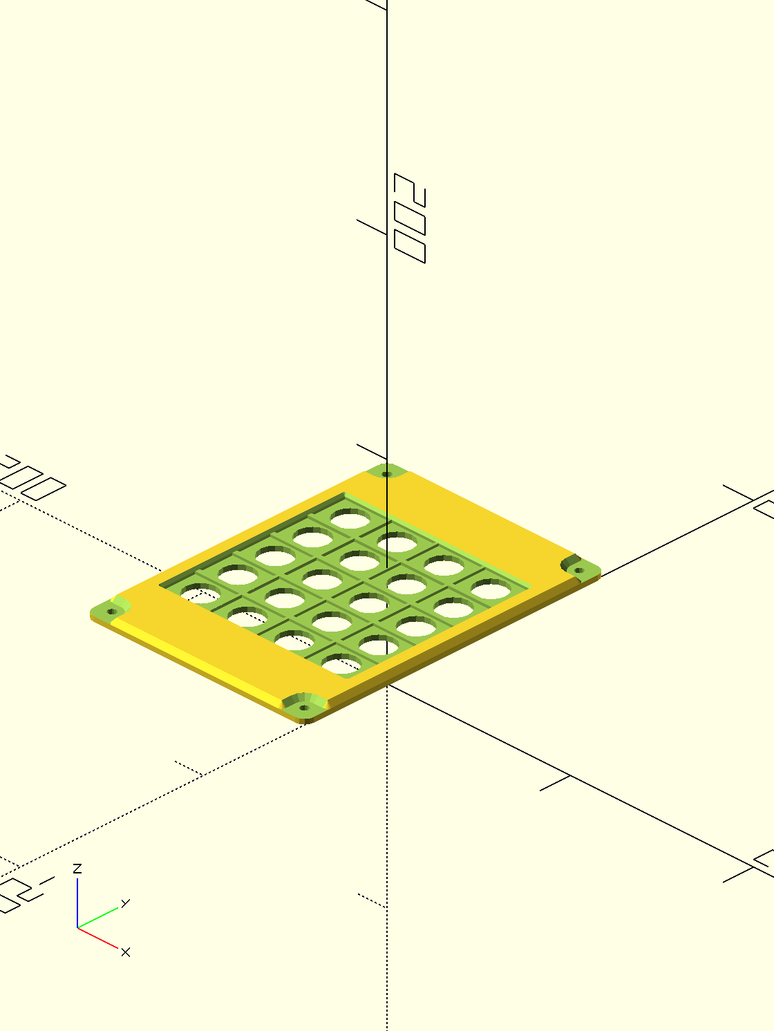
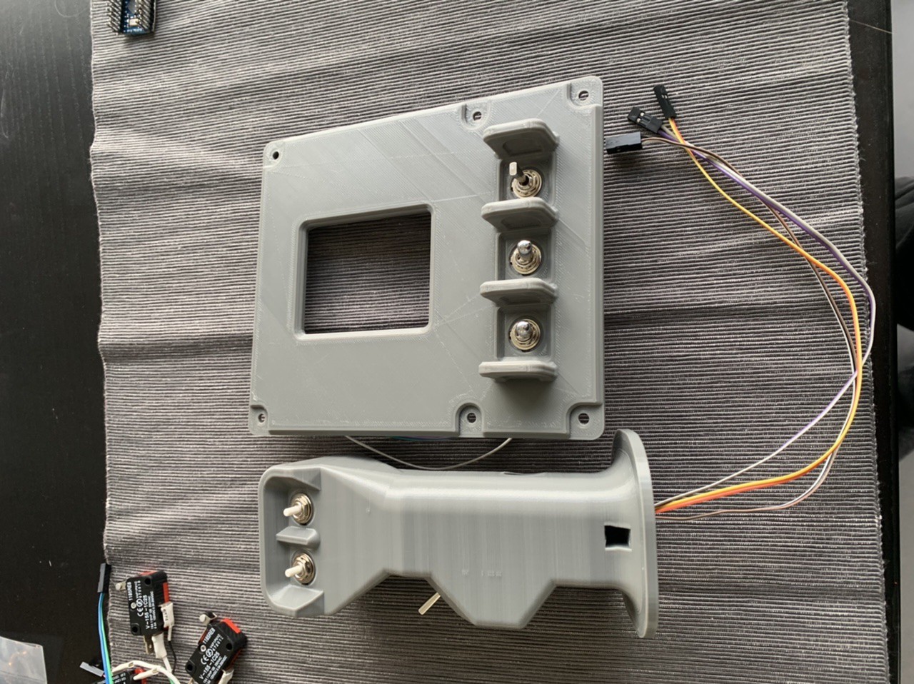
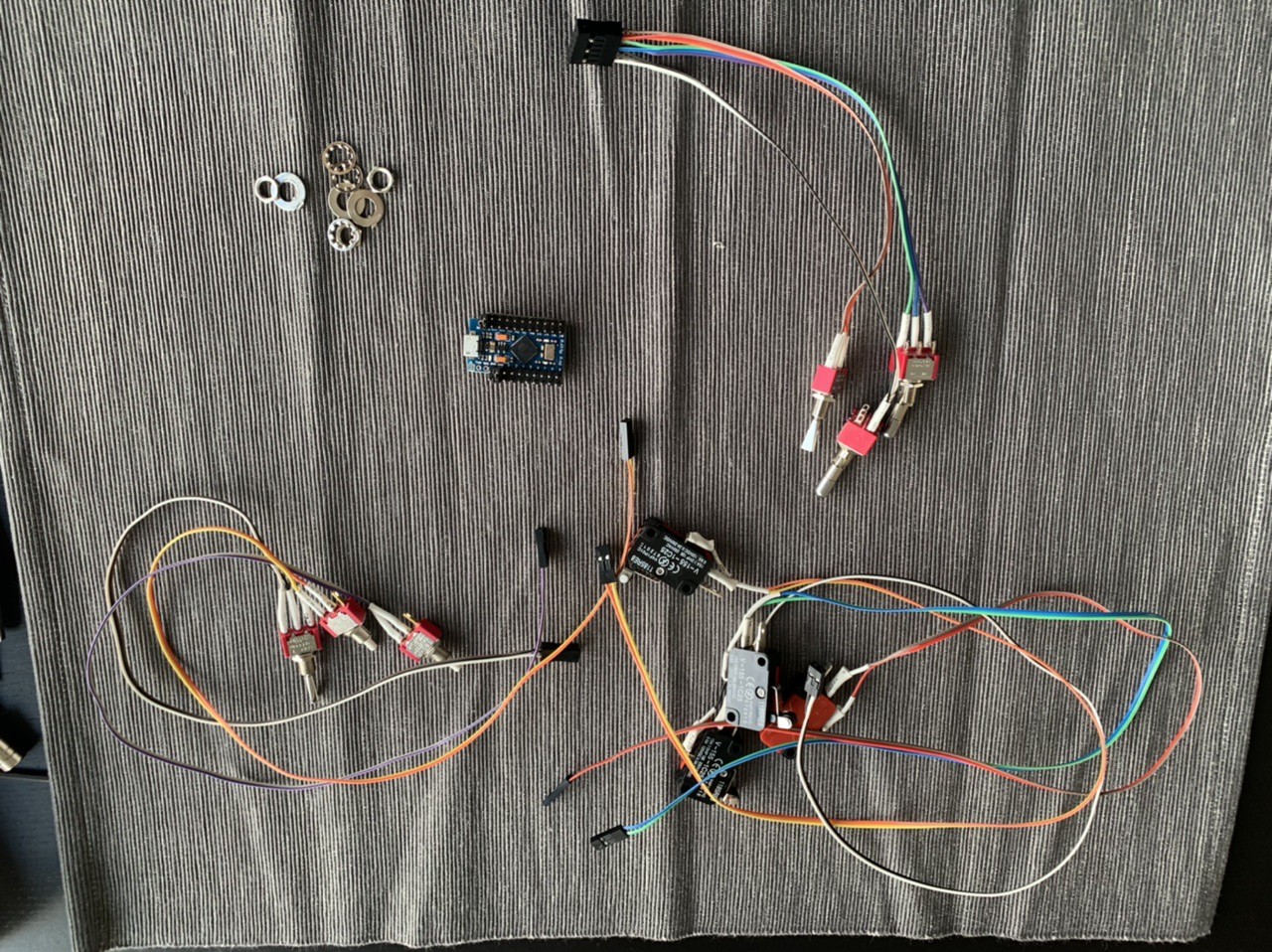
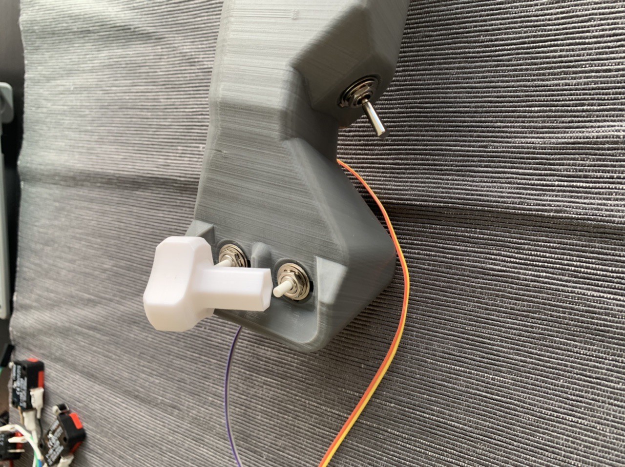
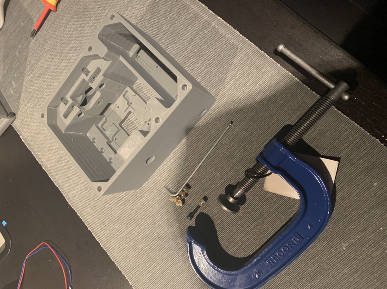
KSP Controller Hardware
Building a set of controllers for Kerbal Space Program including attitude, translation, throttle and hotkey inputs
 Tobias
Become a Hackaday.io member
Already have an account? Log in.
Just one more thing
To make the experience fit your profile, pick a username and tell us what interests you.
Pick an awesome username
hackaday.io/
Your profile's URL: hackaday.io/username. Max 25 alphanumeric characters.
Pick a few interests
Projects that share your interests
People that share your interests

 Nick Rehm
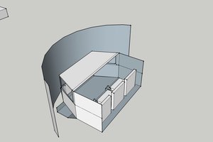


 risknc
I love OpenSCAD and I love KSP, so very excited to see this one develop.