Knowing that the 555 can be used for Boolean logic, I developed the bock diagram below. Although I’m sure there are more efficient implementations, I tend to work through the design before looking at any reference designs. This helps me avoid getting bogged down in someone else’s solution and tends to produce more unique results (and more frequent facepalms when I overcomplicate something). Each block must have the following function.
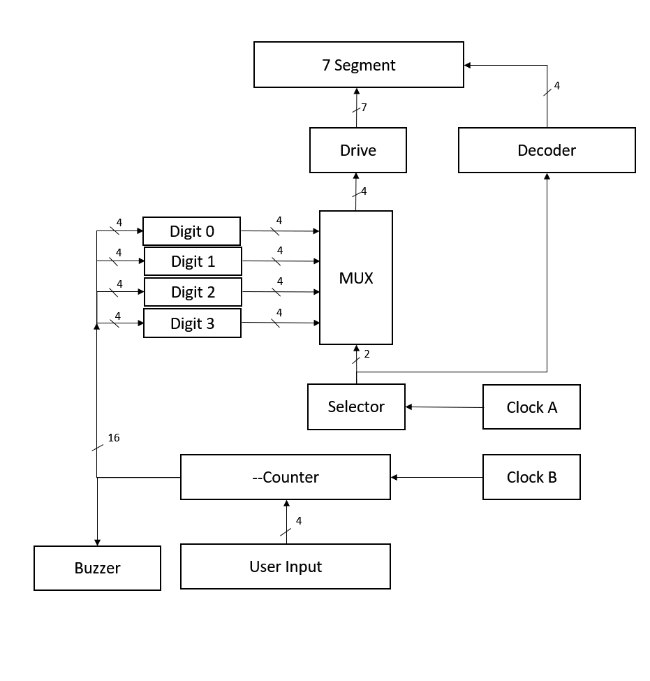
Drive: Input 4 bits representing a single digit of the 7-segment display. The 4-bit input will be mapped to a 7-bit output representing the different elements of a 7-segment digit.
MUX: The multiplexer will route 1 of the 4, 4-bit buses to the drive circuit.
Selector: The “selector” will define the cycling rate for each digit of the display. It could be implemented as a (very exciting) 2-bit counter. The output goes to both the MUX select, and a decoder.
Decoder: This is a basic decoder that takes in a 2-bit input and toggles 1 of 4 bits on the output. The decoder will be used to toggle the common of each digit sequentially.
Clock A: Clock A drives will be greater than ~400Hz and controls the refreshing of the 7-segment display.
Digit #: Stores the 4-bit data, representing a digit 0->9. This block is included as a reference, these digits are incorporated in the flip flops of the counter circuit.
Counter: 16-bit counter (4x 4bits). Counts down in base 10 from 9999 to 0000.
Buzzer: Buzzer circuit that activates when the counter contains all zeros.
Clock B: Clock B drives the countdown timer block at 1 tick per minute.
User Input: The user will be able to toggle each digit by injecting clock pulses into the different blocks of the counter circuit.
Discussions
Become a Hackaday.io Member
Create an account to leave a comment. Already have an account? Log In.