 adi-miller
I found this old safe that died due to a leaking battery. It just needed some cleanup and re-soldering of the connectors to make it work again. There is a button inside that lets you reset the pin, so overall it was operational.
When I was about to place it somewhere for actual use, I started to think what would be a good pin code to use, one that I will remember for years to come and that isn't one of the "regular" pins we use at the house, so that my kids wouldn't be able to figure it out. That made me think about using an Authenticator-based time-based one-time passwords (TOTP).
The way this safe (and I assume many other) work is using a large lock metal bar, that can slide in and out. Once out (locked), the spring on the edge of the solenoid jumps out and prevents the lock from going back in, hence the safe cannot be unlocked.
To unlock it again, you can either use the key (in the middle, not very visible in these photos), or if the solenoid will pull itself back. This of course happens when there is current running through it. The control board manages that part. It will fire the solenoid when the correct pin is entered.
The pin is entered using the keypad on the other side of the door. The green-ish ribbon is the connection between the keypad and the control board.
The plan is to replace the control board with a D1 Mini that will control a relay. The relay will close a circuit between the power supply and the solenoid for a few seconds, thus opening the safe, when the correct pin is entered. We'll need to also connect the original keypad to the D1 Mini for input, and also to add a buzzer for feedback.
The D1 Mini will need to be connected to the WiFi so that it'll be able to sync the clock. This is required for the TOTP to work. We'll need to write some simple code that accepts input from the keypad and after 6 digits will compare it to the current TOTP. If it matches, it will close the relay for a few seconds to allow the safe to open.
In the pictures you can see the final setup.
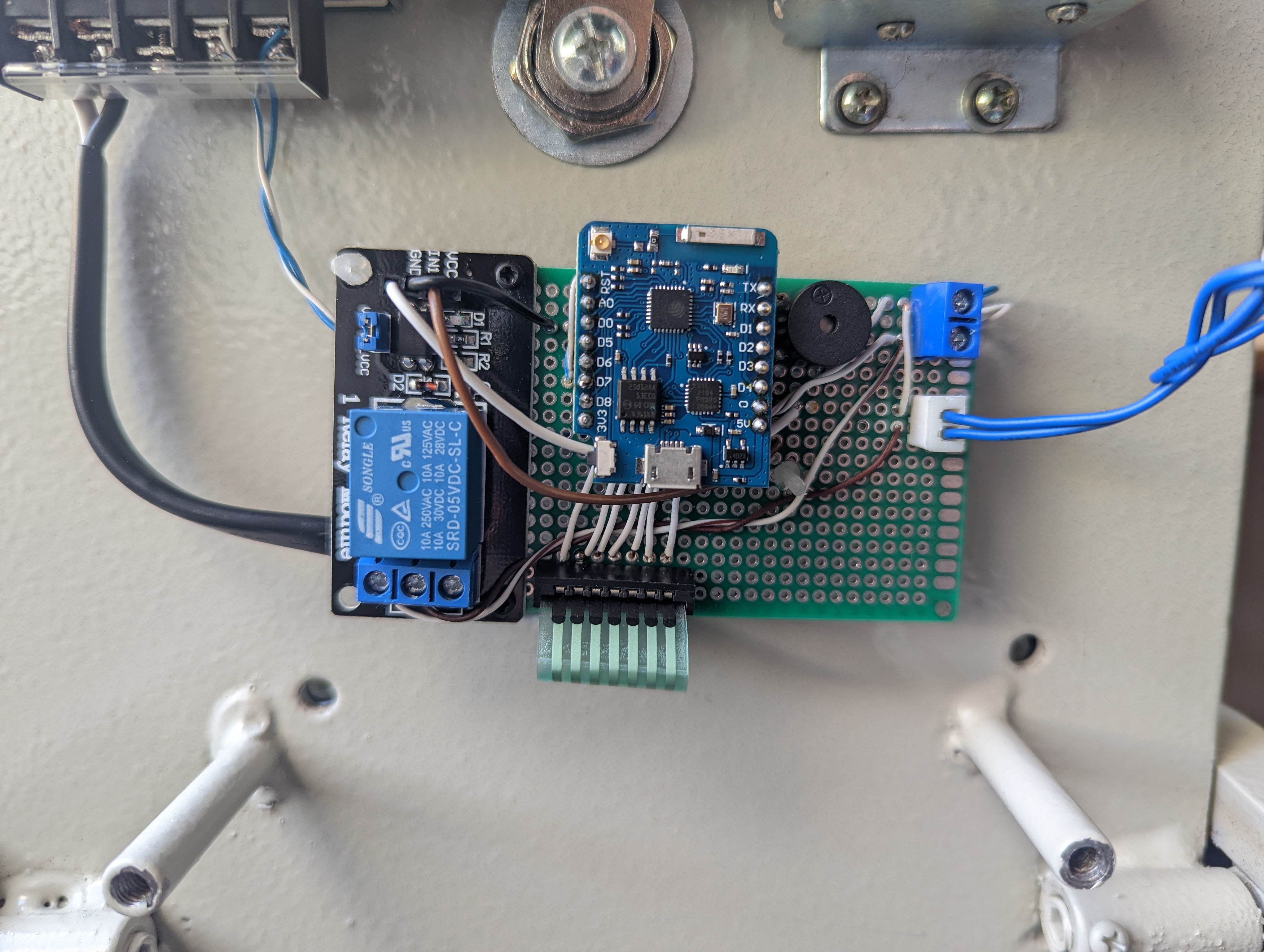
- I used a relay module, but a bare relay can be used as well, with the needed adjustments to the board.
- I also used some connectors that I had, for power, for the solenoid and for the keyboard (harvested that one from the original board).
- I used a 5v 2A power supply, but that's probably an overkill for this solenoid. You can probably get away with something smaller that can be placed outside the box. Just make sure not to expect the D1 Mini to drive the solenoid directly.
The most difficult part was to figure out how the keypad works.
In general, 3x4 keypads connect using 7 wires. 1 for each row and 1 for each column. The rows are pulled high and the columns are low, and when a key is pressed it closes the circuit and that's how the controller can figure out which key was pressed. Here is a good article that explains this: How to Set Up a Keypad on an Arduino - Circuit Basics.
So I had to figure out the order of the wires on the ribbon, and associate each with the right row / column. This required some trial and error. I used a voltmeter in diode mode to check each pair while pressing the various keys until I saw the voltmeter indicating the circuit is closed.
While I was expecting the wires to be ordered (i.e. wire 1-4 for rows and wire 5-7 for columns), it turned out that the correct order for my keypad is:
Wire 1 - Column 1
Wire 2 - Row 1
Wire 3 - Row 2
Wire 4 - Column 2
Wire 5 - Row 3
Wire 6 - Column 3
Wire 7 - Row 4
Each wire from the keypad connects to a different pin in the D1 Mini. I used the following mapping, but you can obviously connect it differently. You will need to refer to this later in the code.
const byte ROWS = 4;
const byte COLS = 3;

char hexaKeys[ROWS][COLS] = {   {'1', '2', '3'},    {'4', '5', '6'},    {'7', '8', '9'},    {'A', '0', 'B'}
};

byte rowPins[ROWS] = {TX, RX, D2, D4};
byte colPins[COLS] = {D5, D1, D3};
Note that I used...
Read more »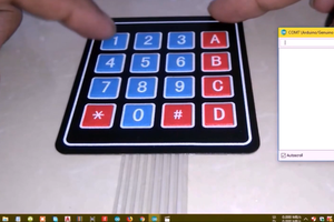
 Harsh
Harsh
 Paul Andrews
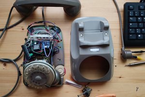
 Giulio Pons