Subhajit
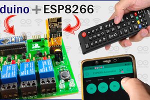
In this IoT project, I have shown how to make an IoT-based Arduino Smart Home with Google Assistant & Alexa using ESP-01 to control 4 home appliances with voice commands, IR remote, and manual switches.
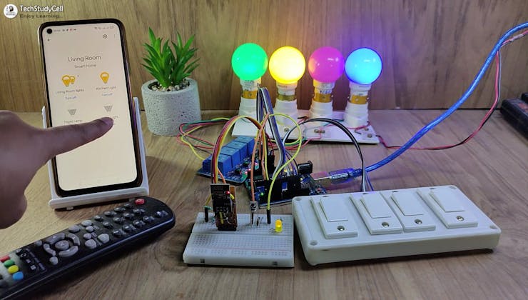
If the internet is not available, then you can control the home appliances from IR remote & manual switches. During the article, I have shown all the steps to make this smart home system.
Tutorial video on Arduino IoT Project
This Arduino Home Automation system has the following features:
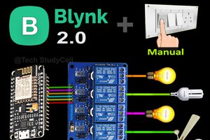
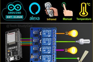
- Control appliances with Google Assistant.
- Control appliances with Alexa.
- Used Arduino EEPROM to remember previous states
- Control appliances with IR remote.
- Control appliances manually with switches or pushbuttons
- Monitor real-time feedback in the Google Home and Amazon Alexa App.
- Control home appliances manually without internet.
- All resources used for this project are FREE.
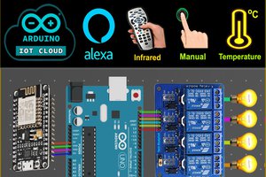
So if you follow all the steps, you can easily make this IoT project just by using Arduino UNO, ESP01, and relay module.
Although the PCB is not mandatory, I have used PCB to make the circuit compact and give the project a professional look.
How does this Arduino IoT Project Works?
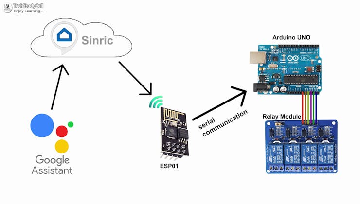
This Arduino ESP8266 Home Automation works in the following steps.
- When you ask Google assistant to control appliances, it sends the signal to the Sinric server,
- ESP-01 will receive the signal from the Sinric through the internet.
- ESP-01 sends the same signal to Arduino through the serial terminal.
- Arduino UNO will process that signal and accordingly turn on or off the relays.
- Arduino sends the feedback to ESP-01 through the Serial communication.
- ESP-01 sends feedback to the Sinric server through the internet.
- Real-time feedback can be monitored in the Google Home or Amazon Alexa app.
Required Components for this IoT Project (without PCB)
- Arduino UNO
- ESP-01
- 1838 IR receiver (with metal case)
- 1k, 2k, 4.7k resistors (1/4 watt)
- 5-mm LED
- 1117 3.3V voltage regulator
- 4-channel 5V SPDT Relay Module
- Switches or Push Buttons
- FTDI232 USB to TTL
- 5V DC supply.
Required Components for the Arduino control Relay PCB:

- Atmega328P microcontroller
- ESP8266 ESP01
- PC817 Optocuplors (4 no)
- 510-ohm 0.25-watt Resistor (4 no) (R1 -- R4)
- 1k 0.25-watt Resistors (6 no) (R5 -- R10)
- 2k 0.25-watt Resistor
- 4.7k 0.25-watt Resistor
- 10k 0.25-watt Resistors (2no)
- 22pF ceramic capacitor
- 104 ceramic capacitor
- 220uF 25V Capacitor (2no)
- 1uF Box capacitor (1no)
- 16MHz Crystal
- LED 5-mm (6 no)
- 1N4007 Diodes (4 no) (D1 -- D4)
- Push Buttons (8 no)
- BC547 Transistors (4 no)
- Relays 5v (SPDT) (4 no)
- Terminal Connectors
- Jumper (5no)
- Switch (1no)
- Hi-link ac-dc 220v-5v
Circuit Diagram of the ESP01 Arduino Control Relays
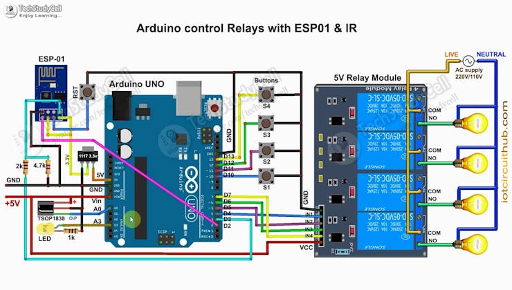
The circuit is very simple, I have used the digital pins D4, D5, D6 & D7 to control the 4 relays.
And the digital pins D10, D11, D12 & D13 are connected with pushbuttons to control the 4 relays manually.
The output pin of the IR receiver is connected with A0.
I have used the INPUT_PULLUP function in Arduino IDE instead of using the pull-up resistors.
I have used D7 as RX and D8 as TX for the serial communication with the ESP-01 module.
I have made a voltage divider using 2k and 4.7k resistors to drop down the 5volt logic level to 3.3volt logic level for the serial communication with the ESP-01 module.
If you use Arduino UNO then you can use the 3.3V pin instead of the 1117 3.3V regulator to supply the ESP01 but for Arduino Nano, you have to use the 1117 3.3V voltage regulator.

If you use the latched switches then just connect the switches across the digital pins and GND instead of pushbuttons.
I have used a 5V mobile charger to supply the smart relay module.
Please take proper safety precautions while working with high voltage.
Create an Account in Sinric Pro

First, visit https://sinric.pro/
You have to create...
Read more »