 hesam.moshiri
Nowadays, Lithium batteries are used extensively in portable devices, such as cellphones, laptop computers, electronic gadgets, … etc. There is a standard industry-defined procedure (cycle) for charging the lithium-ion/lithium-polymer batteries, otherwise, the lifetime of the batteries is reduced significantly or even they might explode and catch fire. As a basic rule of thumb, a lithium battery should be charged at the rate of 0.5C to 1C. In this article/video, I have introduced a universal double lithium battery charger that the charging current (C rate) can be adjusted simply by changing a resistor value. You just need a 5V power source (such as a mobile charger) and a USB Type-C cable.
To design the schematic and PC, I used Altium Designer 22 and the SamacSys component libraries (Altium Plugin). To get high-quality PCB boards, I sent the Gerbers to PCBWay and purchased original components using componentsearchengine.com. To examine the charging current/voltage, I used the Siglent SDM3045X multimeter. Isn’t cool?!, So let’s get started!
Circuit Analysis
Figure 1 shows the schematic diagram of the device. The heart of the circuit (IC1 and IC2) is the MCP73831 chip from Microchip [1].

Figure 1, Schematic diagram of the Lithium-Ion/Lithium-Polymer USB Type-C Charger
According to the MCP73831 datasheet: “The MCP73831/2 devices are highly advanced linear charge management controllers for use in space limited, cost-sensitive applications. The MCP73831/2 are available in an 8-Lead, 2 mm x 3 mm DFN package or a 5-Lead, SOT-23 package. Along with their small physical size, the low number of external components required make the MCP73831/2 ideally suited for portable applications. For applications charging from a USB port, the MCP73831/2 adheres to all the specifications governing the USB power bus. The MCP73831/2 employs a constant-current/constant-voltage charge algorithm with selectable preconditioning and charge termination. The constant voltage regulation is fixed with four available options: 4.20V, 4.35V, 4.40V, or 4.50V, to accommodate new, emerging battery charging requirements. The constant current value is set with one external resistor. The MCP73831/2 devices limit the charge current based on die temperature during high power or high ambient conditions. This thermal regulation optimizes the charge cycle time while maintaining device reliability.”
The charging current of the chip can be programmed from 15mA to 500mA which covers the majority of applications. MCP73831 has one main difference with MCP73832 which is the charge status pin. I decided to select MCP73831 for this project. Figure 2 shows the charging cycle of the chip which is a complete charging cycle.
 Figure 2, Complete charging cycle of a 100mA battery (ref: datasheet)
C1, C2, C3, and C4 are used to reduce the supply noise. D1 is an LED that indicates a proper supply (Type-C cable) connection. R1 limits the current to the LED.
CON1 is a Type-C female USB connector. R2 and R4 define the charging current of the H1-P1 and H2-P2 battery connectors. D2 and D3 indicate the charging status. An ON LED indicates a completed charging cycle. The charging current can be calculated using equation 1. So the maximum charging current (500mA) is achieved using a 2K resistor.

Equation 1, Charging current calculation formula for IC1 and IC2
PCB Layout
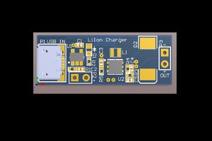
Figure 3 shows the PCB layout of the design. It is a two layers PCB board. To get high-quality fabricated boards, I sent the Gerbers to PCBWay and received 10 PCBs. All components, except for the battery holders/connectors are SMD.

Figure 3, PCB layout of the Lithium-Ion/Lithium-Polymer USB Type-C Charger
When I decided to design the schematic and PCB for this project, I realized that I don’t have the component libraries of IC1 and IC2 [2] in my component libraries storage. So as usual, I selected IPC-rated SamacSys component libraries and installed the missing libraries (schematic symbol, PCB footprint,...
Read more »

 FrazzledBadger
 Sagar 001
 Jon Thomasson
Yyou should really add two 5.1K resistors - from each CC pin of the Type-C connector to ground! Without them, not all Type-C power supplies will work - my experience is that only a USB-A to USB-C cable will power your board consistently, for C to C cables, there's zero guarantees here! Four 10K resistors in two parallel pairs will also work.