 kelvinA
The title is a play-on-words of GAAFET, standing for Gate All Around, Field Effect Transistor.
Now that the #Coaxial8or [gd0144] is in a bit of a break period as I wait for the new heatblock design to be fabricated and arrive, I have been looking into Tetrinsic again. I still feel like if I had to choose 1 single project to "get past the post" (i.e. design, manufacture and implement into my daily life), this is it; unlike 3D printers and XR glasses, I unfortunatley haven't found enough information on the internet that suggests that some company would come out of "stealth mode" with a sufficient offering, and even if one did come out today, they'd most likely say it will start shipping "in months" but implications would mean that "in years" would be more accurate. On the other hand, I haven't been able to indirectly find this project through my search queries, so there could still be similar projects and solutions that I haven't come across yet.
Anyway, I came across this video about linear shaft engineering:
My strategy I thought up back in September 2023 was the U-shaped linear motor, just with the coils and magnets swapped around. This aleviates the cooling drawback they mentioned, but understandably still has the drawback they mentioned where only half the magnetic flux generated by the coils used (the other half is in the opposite direction).
The video states:
Force (N) = Current (A) x Magnetic Flux Density (T)
Thus, for a fixed current, more force is generated with a higher density. This also suggests that, for this application, it's better to drive the system with as low a voltage as possible.
Looking into the DRV8311, they're just simple H bridges at the end of the day so it's not like the chip is doing anything fancy with the input voltage. Additionally, I found these answers on stackexchange. While doubling the voltage will double the torque, it would quadruple the power required. Thus, since the power for each Tetrinsic is limited to prolong battery life, and I mainly need the torque in very low - low speed situations (e.g. sub 300Hz haptics) higher voltages are actually worse, as are very thin (0.1mm) wires used to make the coil. Instead of 12V, it now sounds like it would make more sense to run everything on 3.3V, which would still allow for up to 16.5W per Tetrinsic.
Additionally, I've read bits and pieces that should lead to improved performance, but this answer brings everything together. For example, it did seem that a thicker magnet would increase strength when reading Doubled Forces, which the user "cinaral" confirms. They also say that the thickness of wire -- thus its current carrying capacity -- roughly balance out with the amount of turns that can physically fit in the space, which sounds like a foil coil is still the more ideal strategy from a heat dissipation and manufacturing standpoint.
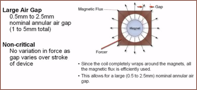
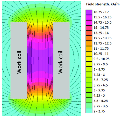
As mentioned in the video, magnets emit their field in all directions. What wasn't mentioned, but probably just as important, is that the coil has it's highest flux density in its centre:
The video proposes a shaft where like-poles are pressed together with no airgap inbetween:
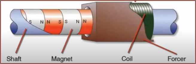
This configuration is probably to force the flux outwards from the magnets:
It likely is also so that the shaft doesn't just act as one massive magnet. With this in mind, the plan is to move from a 10x3x2 to a 10x3x3 magnet so that I can place them in this configuration.
Manufacture
I already knew about linear shaft motors (but not their benefits over U-shaped ones), but the issue is that I still need to actually make a belt or a motor or both. With the U-shape solution, both of these can be made separately, wheras with a coil-all-around solution, one would have to be made in-situ.
Additionally, I need to consider how individual magnets will come together to form a belt in the first place. Since the magnets are relatively small and the belt also needs to slide across the stainless steel tubes with as low friction as possible, a potential idea is to stick the magnets to UHMW tape which acts as the belt, which seems to have all the features I would need.
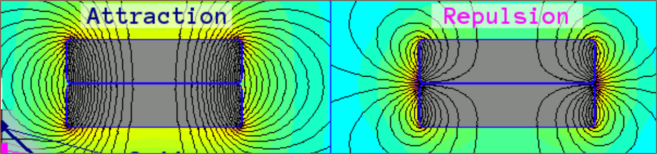
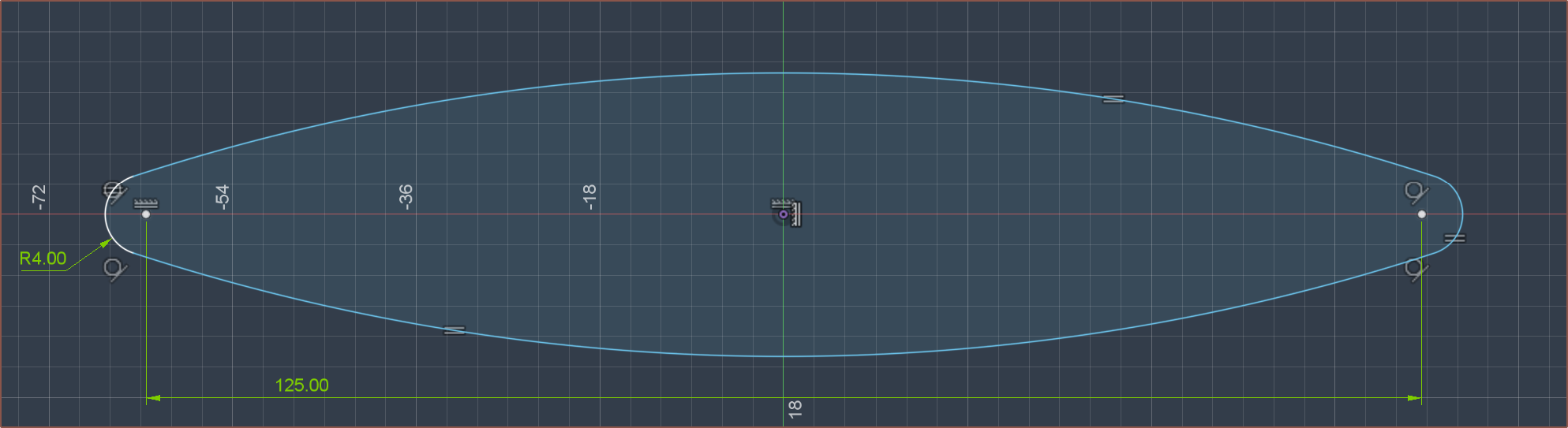
The main concern is that, due to the repulsion forces of the magnets, the flat sections of the belt are expected to inflate outwards like this:
Each magnet will also be trying to push away at each other with up to 700g of force, though that number is likely to be closer to 500gf, which likely will increase the fabrication difficulty. The benefit is that the minimum turning radius can likely be small.
Another solution is to tape both sides so that the living hinge is in the middle:
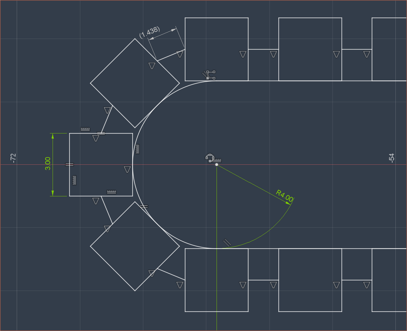
The benefits are that the straights are flatter and the gaps and the potential to use a grippy outer tape will reduce finger slippage. The drawback is that the magnets are spaced further apart (potentially reducing max torque) and the minimum turning radius is more limited (both due to geometric limits and because the repulsion force will be much stronger on the side closest to the pulley.
It's likely still possible to go with the 3D printed vase-mode strategy, whereby a case for the magnets is printed in TPU. In this case, the coils will have to be wound around the belt (thus I won't be able to outsource them).
Discussions
Become a Hackaday.io Member
Create an account to leave a comment. Already have an account? Log In.