 kelvinA
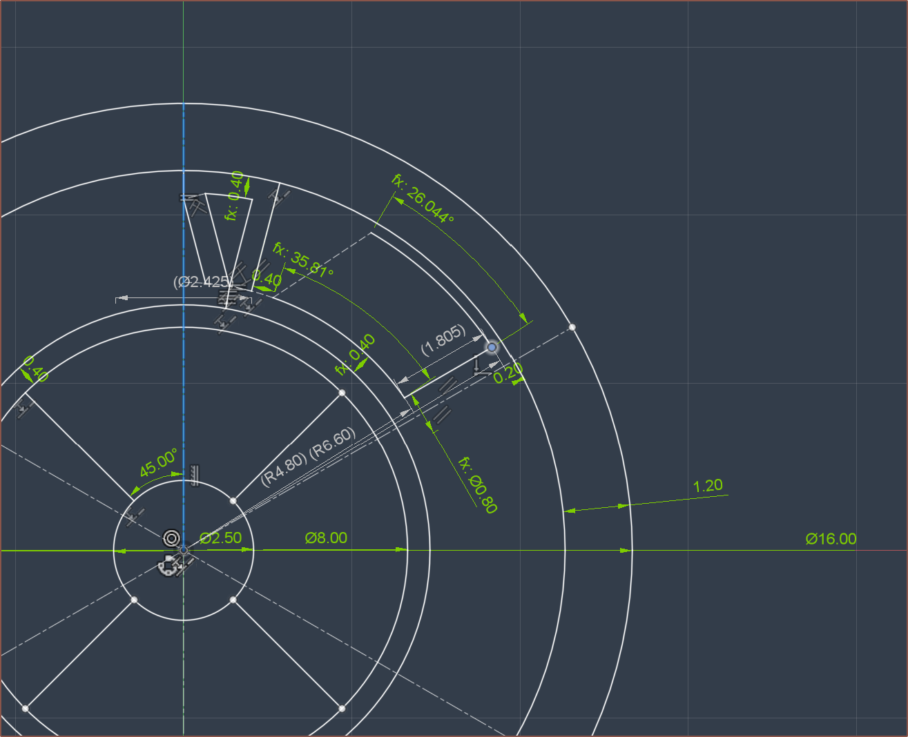
From the centre outwards, you've got:
- 2.5mm shaft
- 2 pole pair magnet of 8mm diameter
- 0.4mm air gap
- 0.4mm spiral vase mode housing print (in PBT ideally, but ABS should be OK)
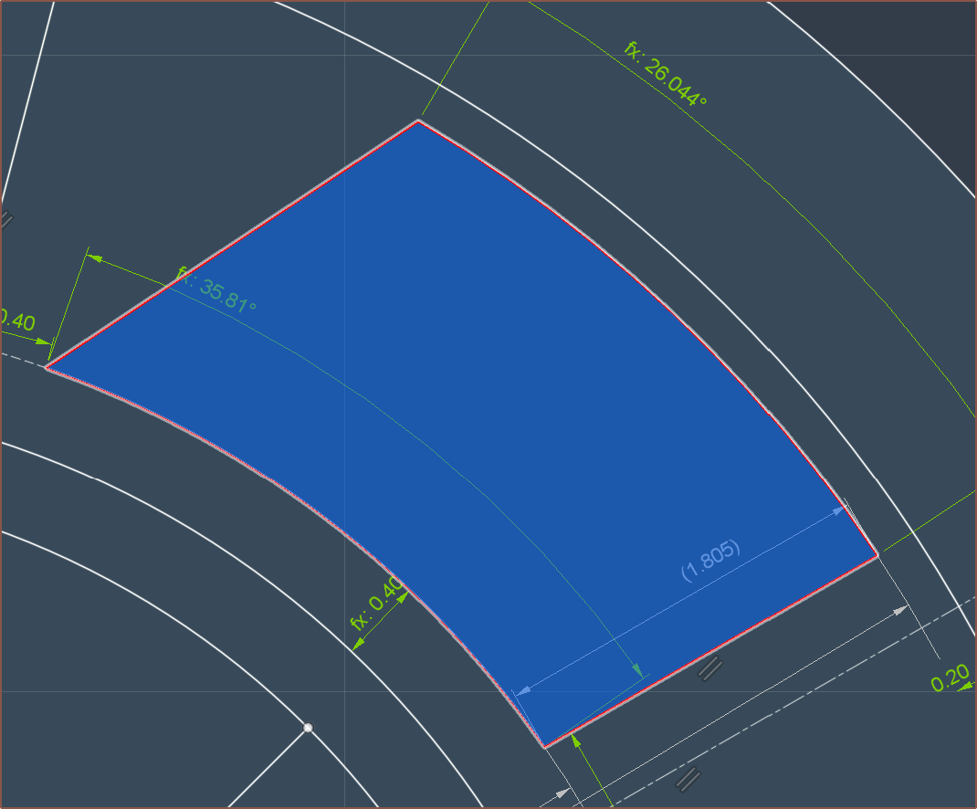
- The space for the copper (1.805mm)
- Coincidentally similar to the 1.85mm copper height in the 580KV motor.
- Tolerance gap of 0.2mm
- Outer lamination yoke that is 1.2mm.
- I opened up the 580KV motor I got to find out what size was used.
Copper foil?
 You might be wondering what this is. This is the approximation of 3mm copper foil stacked on itself. Since copper smaller than the magnet width does not provide any torque (so I've heard), it makes more sense for the tape to hug the edges.
Assuming
- a 0.06mm thick tape, of which 0.03mm is copper
- 90mm stator / rotor length
- 11mm on each end to connect the straights together
I got a copper tape length of 6060mm (6m) and a resistance of 12.1 ohms., which isn't great but kind of tracks compared to the 8.2ohm, $32 motor that looks like it's probably 55mm in total length and thus probably has a 45mm long stator. It obviously doesn't help that less than 50% of the CSA is conductive.
Copper wire
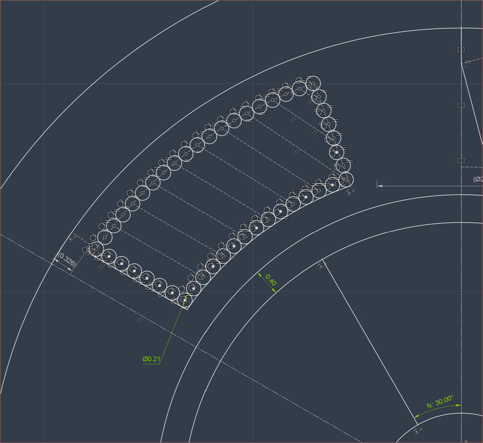
For the more traditional approach, it looks like there will be at least 15 * 8 = 120 turns (or 60 if I decide to double-up) using 0.2mm (32AWG) wire. Estimating for the extra space filling, it's probably going to be at or close to the 130 turns in the paper. It would also seem that a 3-pole-pair rotor would be ideal for this design.
Assuming that the average length to connect the straights is 9.4mm and that 138 turns are used, I get 27434.4mm (27.4m) per coil, which corresponds I get 14.7 ohms.
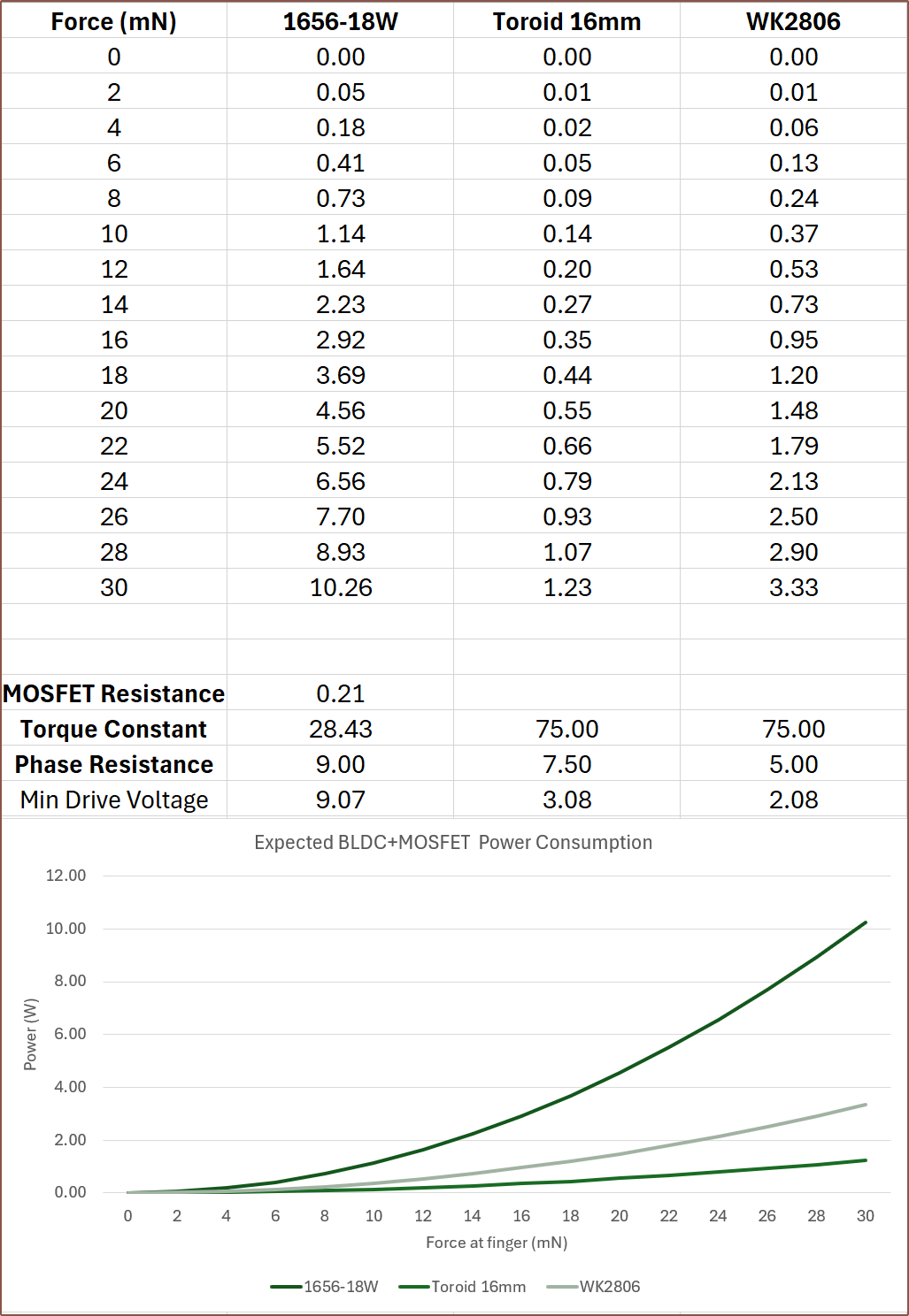
Is that high? Maybe? However, if this design -- with rotor of length 90mm and diameter 8mm -- can match the 75mN.m obtained with the paper's motor (rotor of length 25mm and diameter 11.5mm), The minimum driving voltage and power consumption would suffice:
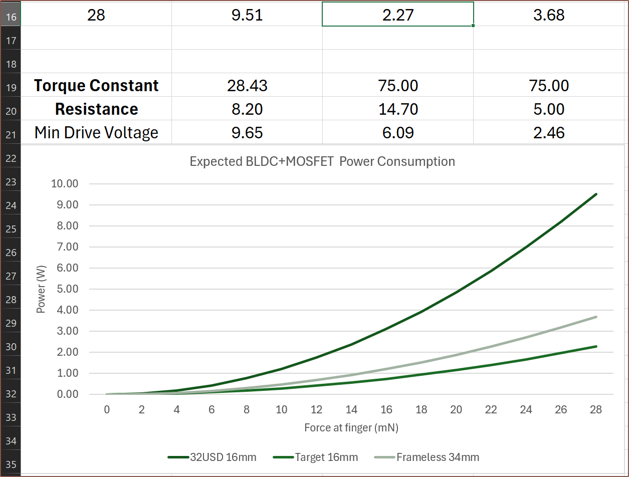
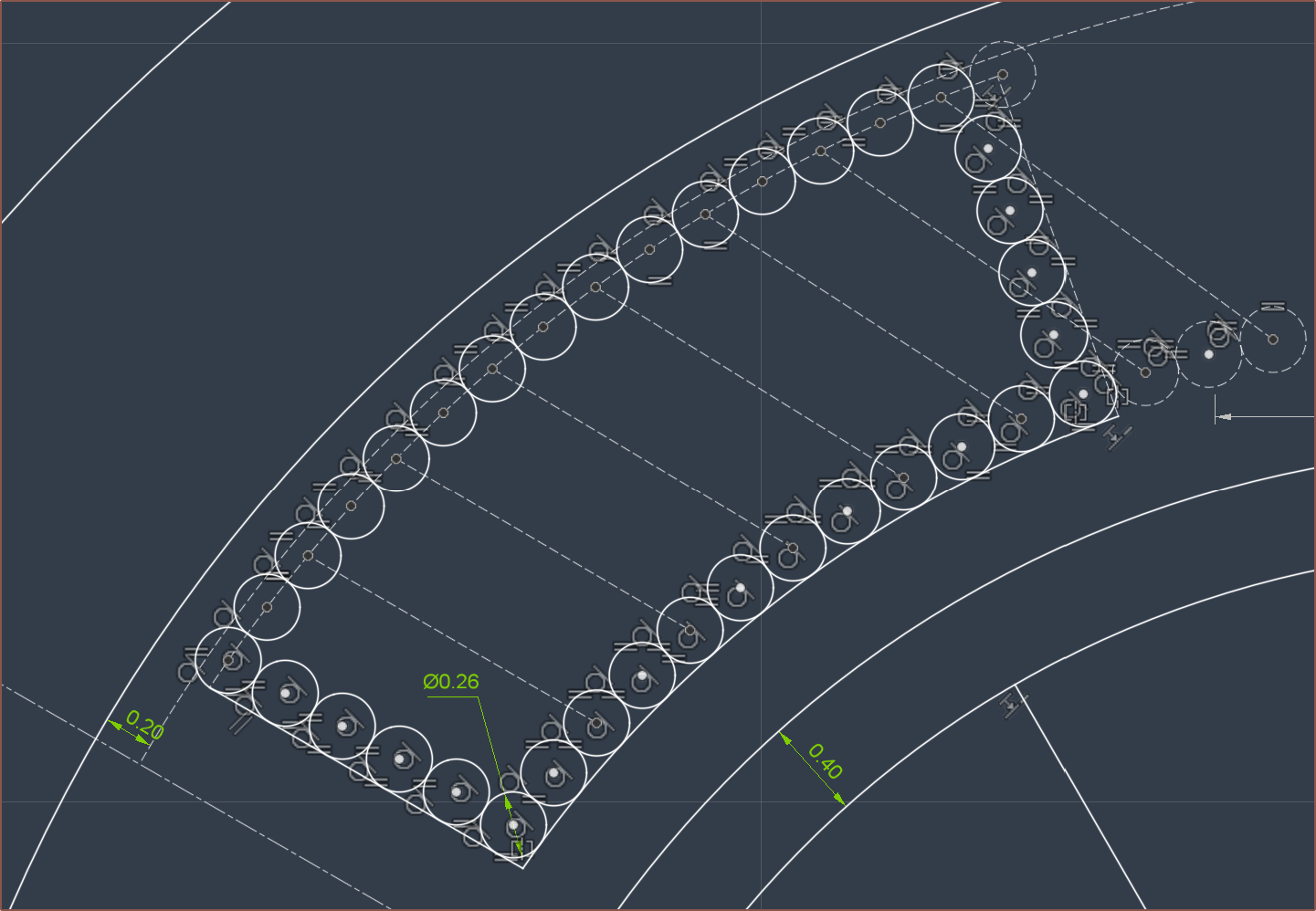
If anything, I worry that the Kt would be too high and the minimum drive voltage would be lower than 6V. Additionally, manually winding dozens of coils for over 100 turns each sounds like it would be laborious. I could always double up the 0.2mm wire, but it seems that it would just be easier to work with 0.25mm wire:
Here, it seems that at least 80 turns would be present, probably something like 82. If my tolerances are good, I could probably fit a 7th row and perhaps get to 90 turns. For 82, the total wire length is 16301.6m and the resistance is 5.4 ohms.
Quick finger tests
So, just to make sure I'm on the correct page, I put my scale against the wall and pushed my fingernail for Finger2-4 (see below) and the max reading across the tests were about 300g, thus I'm correct in aiming for 30mN virtual-endstop force.
Secondly, I played some music, slowed down so that 1/8th of a beat corresponded to the time it took my finger to move 50mm. This is because 16 x PI = 50.3mm. Then, I used an online BPM tapper to get 1/4th, which was 220BPM. Thus, the top RPM I expect to see on the motor is >= 440.
Tube instead of laminations?
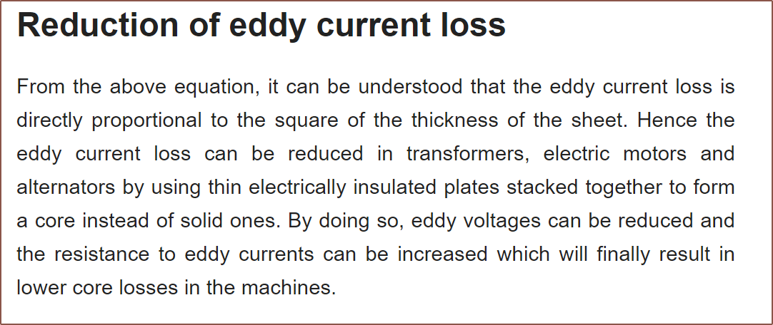
The reason I want to know the top RPM specifically is because eddy current losses are a result of how fast the magnetic flux is changing. Considering that, unlike 99.9% of motor applications, this motor is working at no / low speeds of essentially 500RPM max (unlike the 10K that the authors of the paper called "low speed"), I'm wondering if the eddy current losses will be low enough to use a tube of magnet-permeable material.
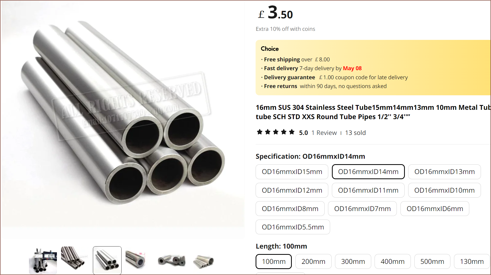
Stainless Steel 304 could be a good choice, as it's readily available and, unlike things like mild steel, doesn't corrode in contact with water. I don't know if magnetic PLA is more or less magnetically permeable, but stainless steel probably would do a better job of dissipating heat.
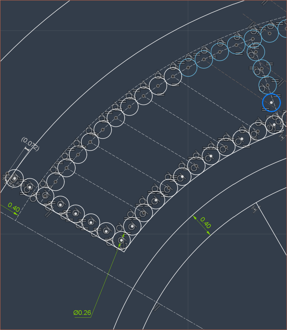
The paper says that the magnetic "air-gap" is essentially from the rotor magnet to the outer yoke and thus should be minimised, and that it's a balancing act between that and winding resistance. For this reason, and the assumption that stainless steel 304 is probably less permeable than the sheet steel used for traditional cores and thus needs more CSA to contain all the flux, OD16x1D13 seems like a good choice. It looks like I'd be able to get 75 - 78 turns:
Assuming that (due to the thicker wire, and the fact that there would probably be a curve and not a straight line like I assumed further above) that the average length between the straights is 13mm, I get 15450mm of wire for 75 turns, corresponding to 5.3 ohms.
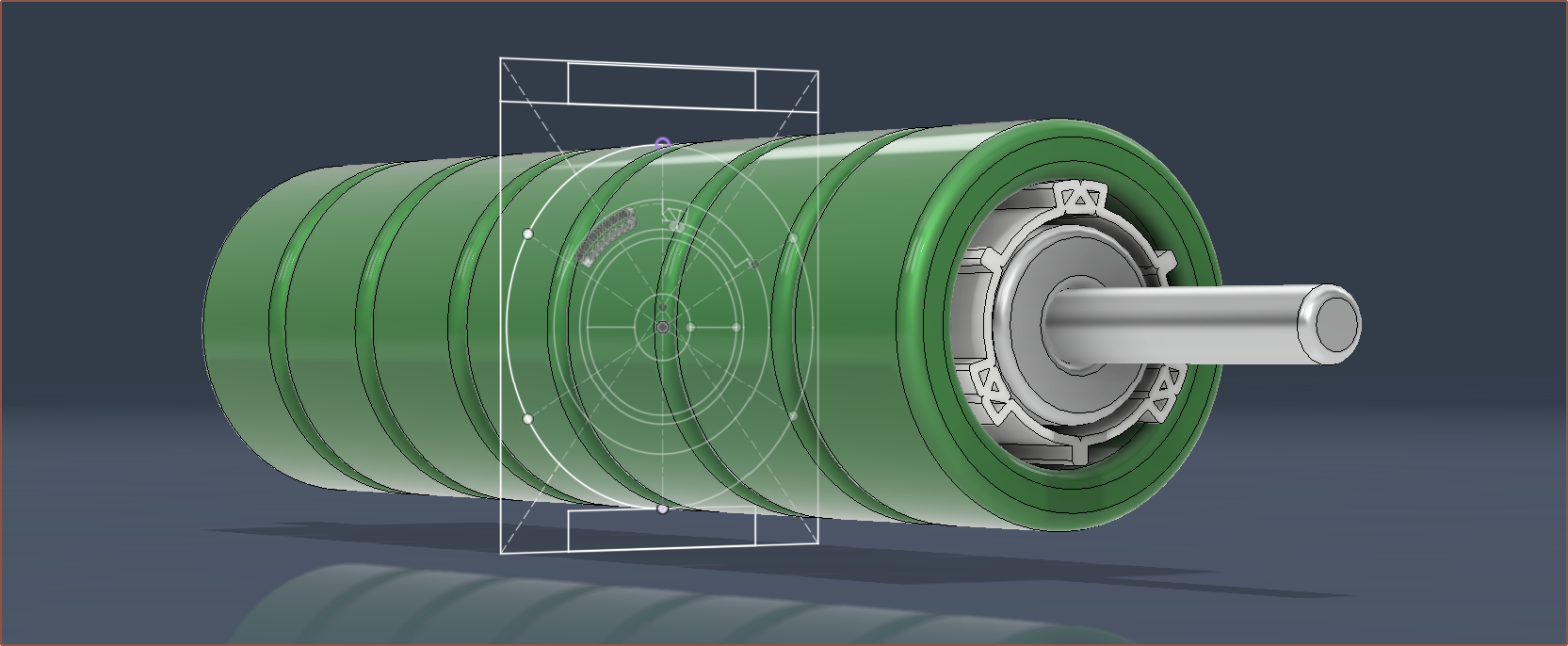
Sketching in 3D
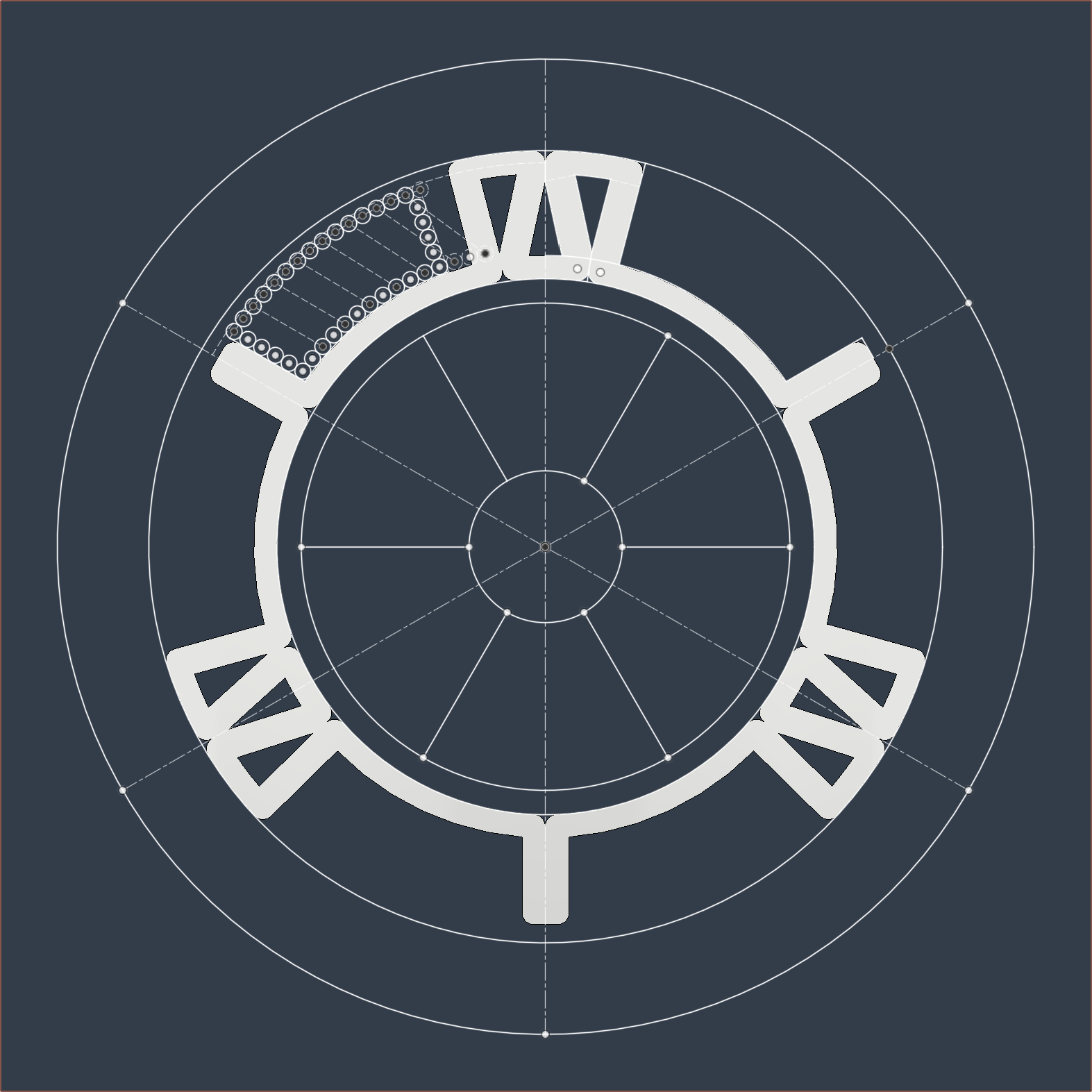 This is what I expect the "overmould" (as the paper calls it) would look like. It seems that I now just need to find a way to aquire a 3-pole-pair magnet ring for the stator. On the other hand, it sounds like the paper highlights that magnets with higher pole counts are more sensitive to the air gap. This kind of makes sense if I imagine that they're separate magnets instead of a single multipole magnet, whereby the field lines would extend a shorter distance if the separate magnets were smaller.
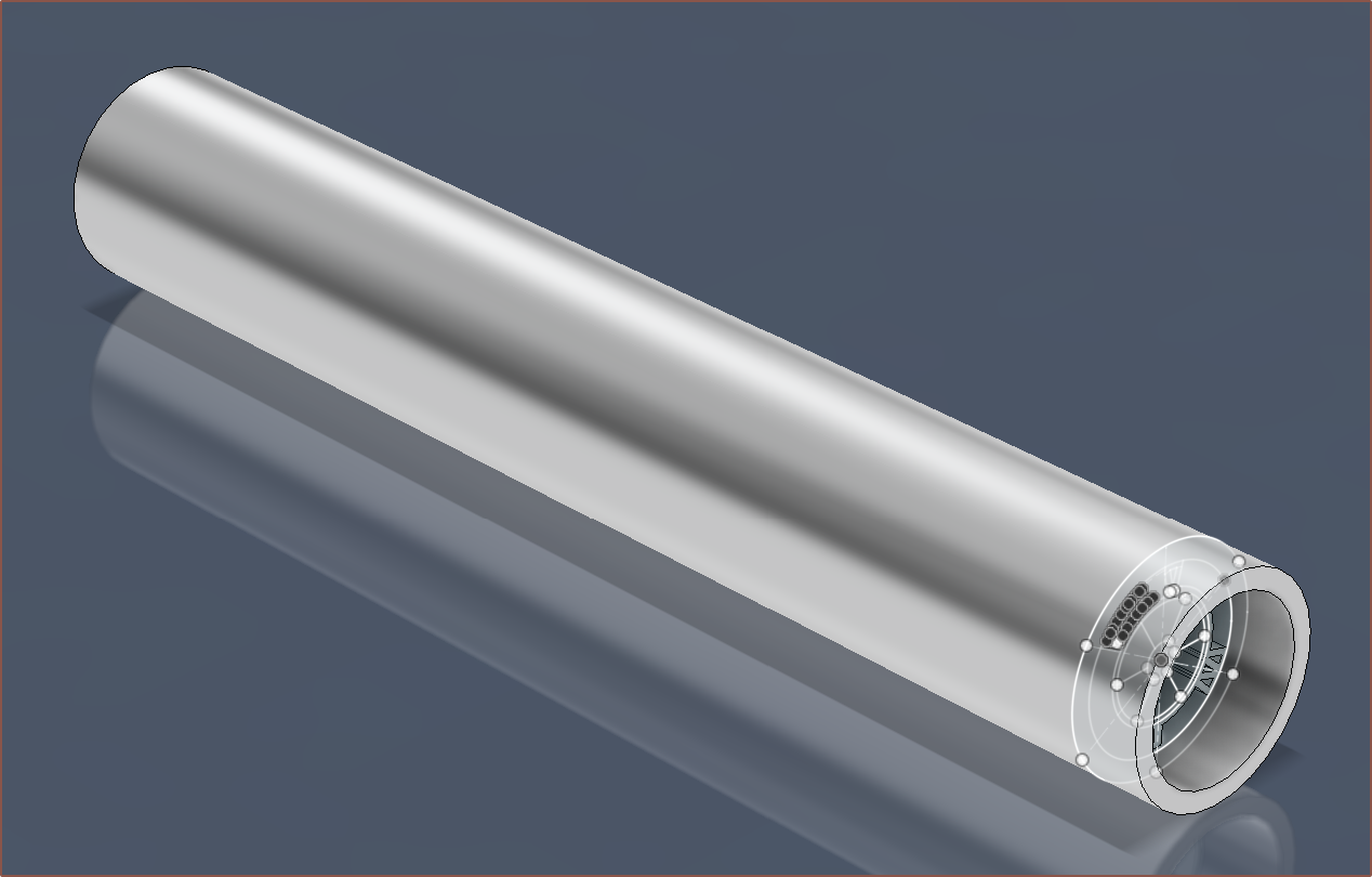 100mm might actually be a tad on the long side, considering that the pulleys + belt would contribute about 40mm to the total length alone, along with another 10mm just for the bevel gear. #Teti [gd0022] can fit 140mm tops, and my not-so-temporary temp keyboard is 125mm. Doing some measurements on the #Tetrescent [gd0150] concept print, it does seem that I'd want to keep the length under 100mm and it probably is closer to the 60mm that I've been seeing in my motor search. The minimum stroke length of Tetrinsic needed is 52mm, so 60 should be ok.
Thus, the rotor length drops to 50mm, thus 9450mm wire length and 3.2ohms. Additionally, this custom motor could potentially be directly compared with the $32 motor, similar to how the authors of the slotless paper compared their motor against a reference. It thus may make sense to use a 3mm shaft over a 2.5mm one (chosen for the smaller bevel gear variant) so that they're otherwise interchangeable.
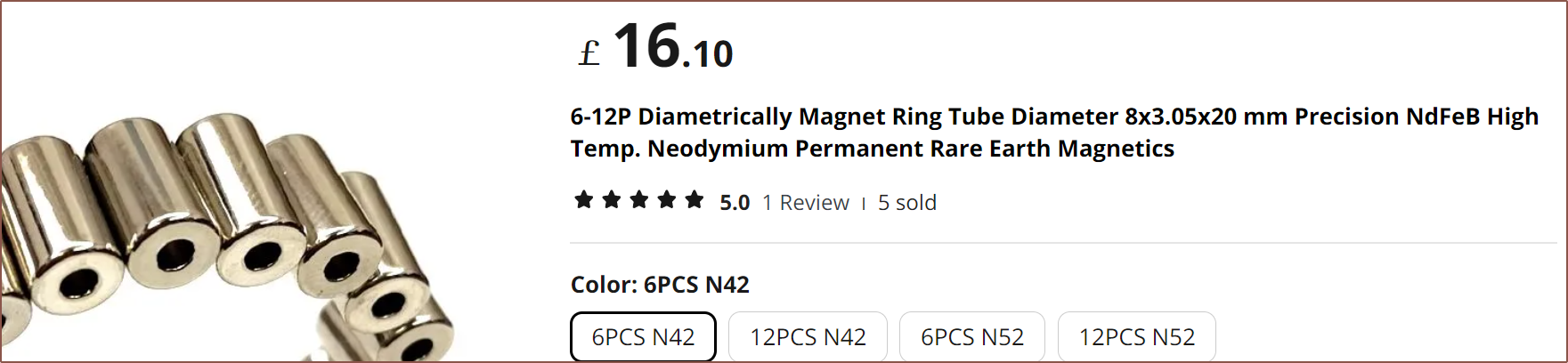
I've create an RFQ on Alibaba for the rotor magnet, and on AliExpress, I've coincidentally found multiple sellers of 8*3.05*20mm diametric (2 pole) magnets:
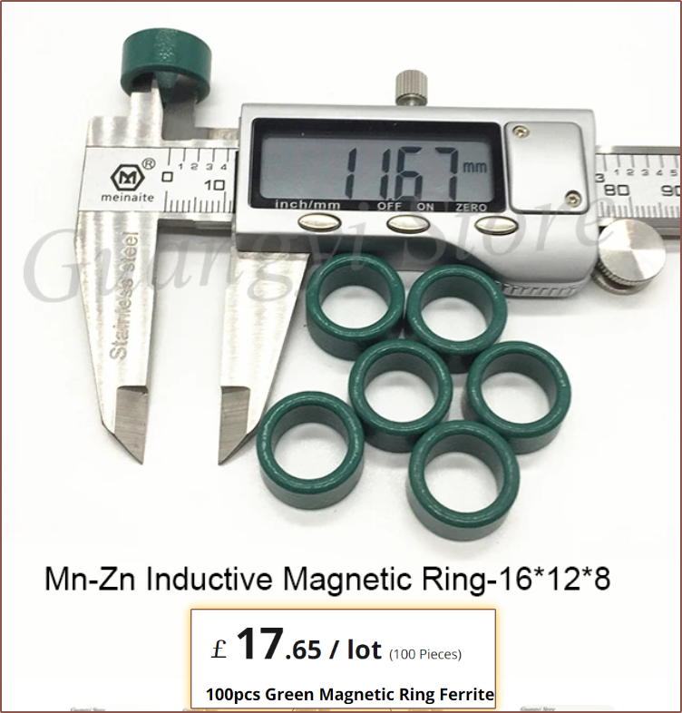
 The slotless paper had a breakdown of normalised prices, and the magnet for the rotor was 52% of the entire cost, so I was expecting that it was going to be rather costly. I also found 16*12*9mm ferrite rings that are a tad bulky on the wall thickness:
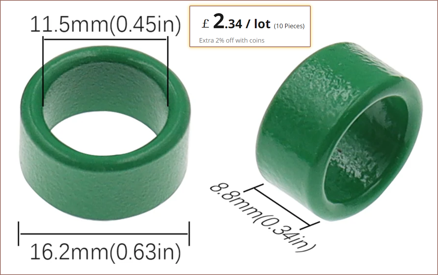
I looked into eddy currents, and it doesn't look good for the solid steel strategy:
Additionally, I'd have to cut the tube down to size. On the other hand, because of the overmould, it would be possible to instead stack multiple ferric rings/toroids to get the length desired. This stuff is used for things like transformers and inductors, and thus probably has the magnetic permeability and saturation thickness required for the job.
With 0.18mm wire, it's possible to have a phase resistance of 7.5 ohms from 78 turns and an assumed average straight-to-straight wire length of 13mm:
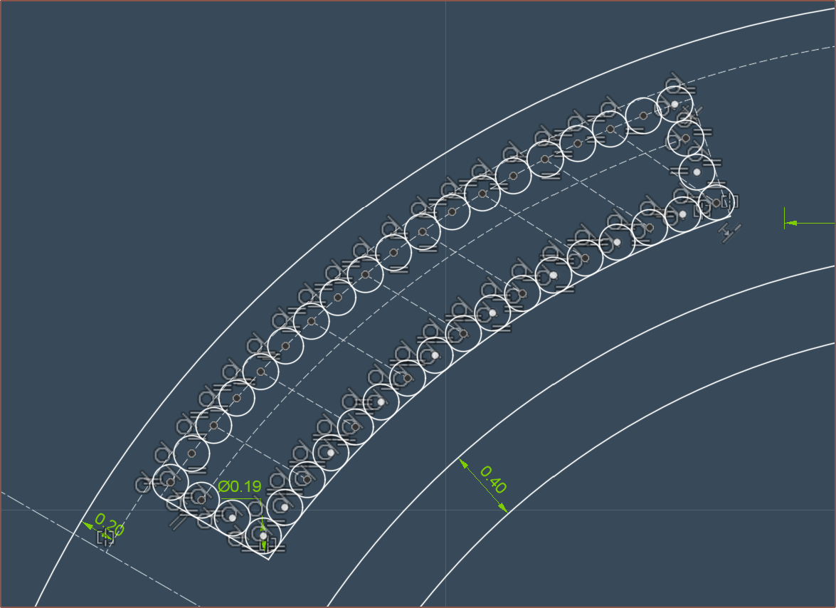
This is good, because the minimum drive voltage is 3.08V, meaning that I hypothetically should be able to use a 3.3V source for everything.
I think the Tetrinsic Toroid is a fitting name for this motor:
As you can see, I'm barely within the maximum target limits of 17mm x 21.8mm, considering that the FSR is 0.25mm and the UHMW tape is probably similar. I'd need a 1.8mm thick belt to stay within limits. As mentioned previously, these limits are so that a finger spacing of 18mm and a body height of 25.4mm can be obtained.
I'd also like to see if I can fit the hall sensors directly inside the motor, since the rotor is a 1pp diametric magnet and all, and so it makes little sense to then stick another one just so that I can get a Sin/Cos readout.
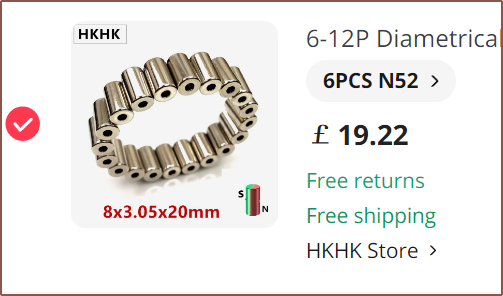
N52 is only about £3 more (so £1.50 more per motor), so I believe it makes sense to go with that. On the other hand, the video below states that magnet strengths come in a range and N52 is the hardest to get consistent, so it might be better to go with N42 since this rotor would be comprised of 3 magnets.
BOM
Thus the incl-VAT cost is already in the ballpark of £15.50 for the magnet, yoke and coils, and a solution will likely converge at under £15/each for the shaft, bearings, printed parts and hall effect sensors. I might also need glue to keep the ferrite toroids together and/or seal from liquids.
Depending on length considerations and the space needed to terminate each end of the motor, I might have to go down to a 40mm stator, which has the benefit of reducing the BOM by £3.84.
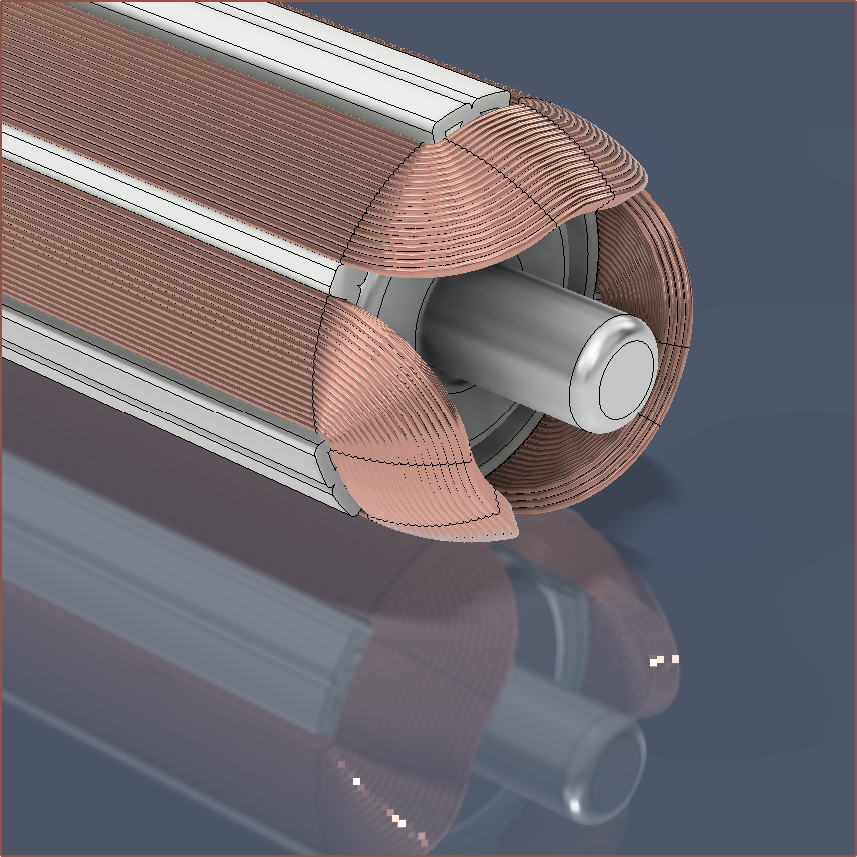
More modelling
Surprisingly, it didn't take much effort to model in the pseudo-coils:
Discussions
Become a Hackaday.io Member
Create an account to leave a comment. Already have an account? Log In.