kelvinA
-
[M] Concept 3.2X2 modelling... started.
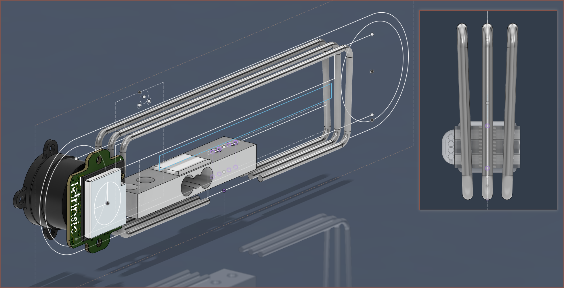
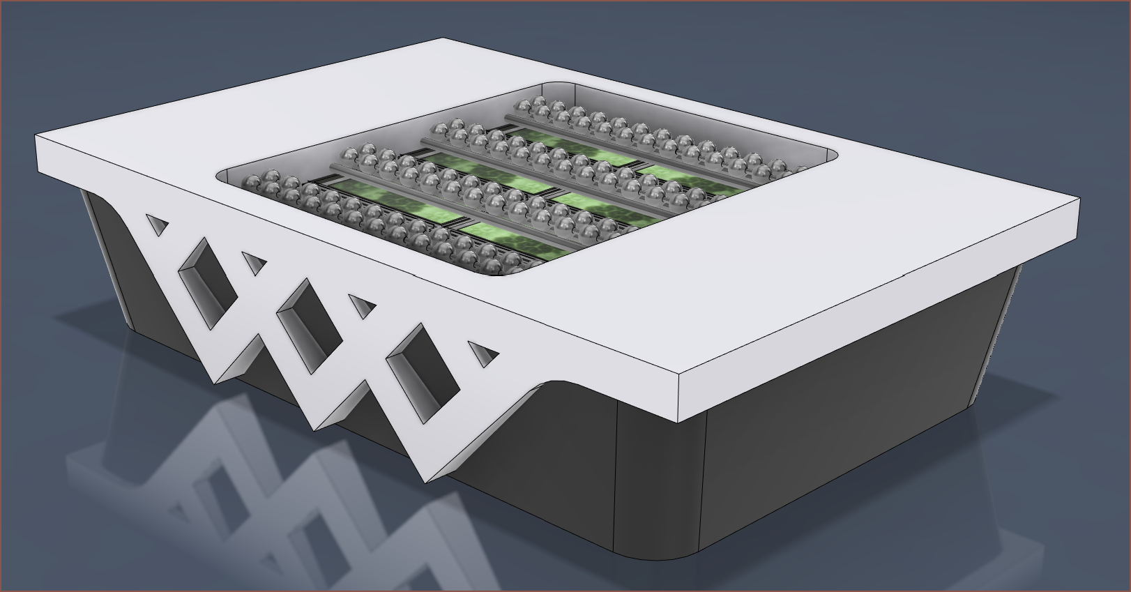
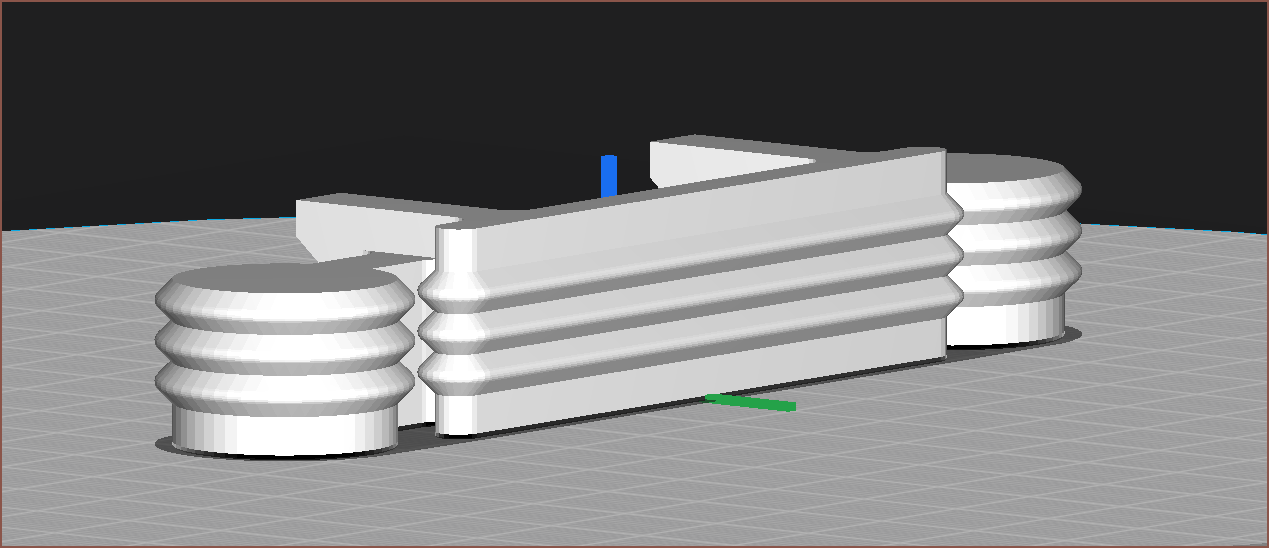
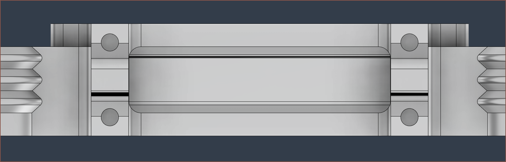
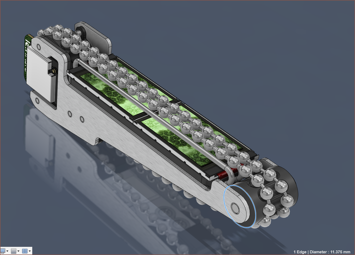
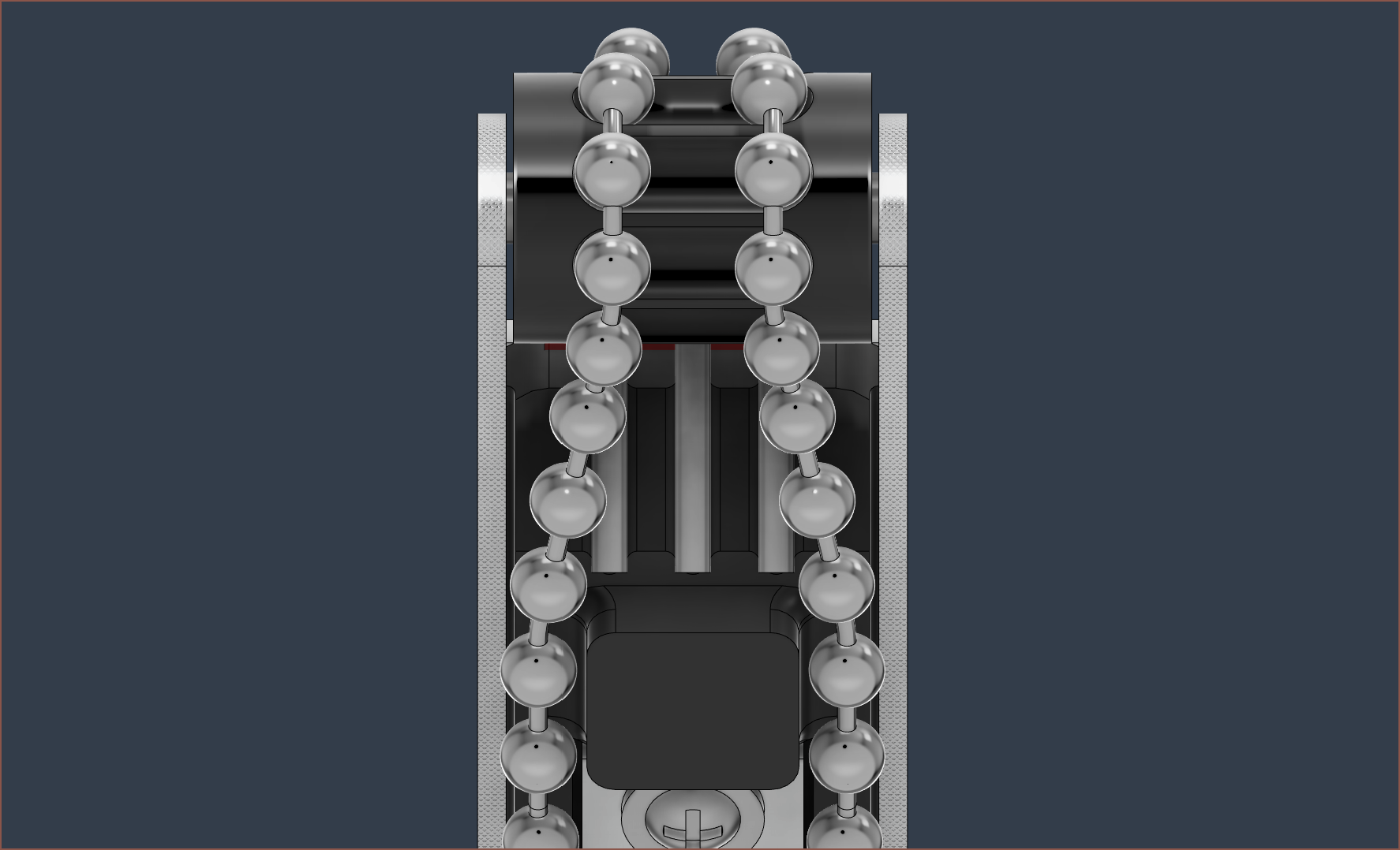
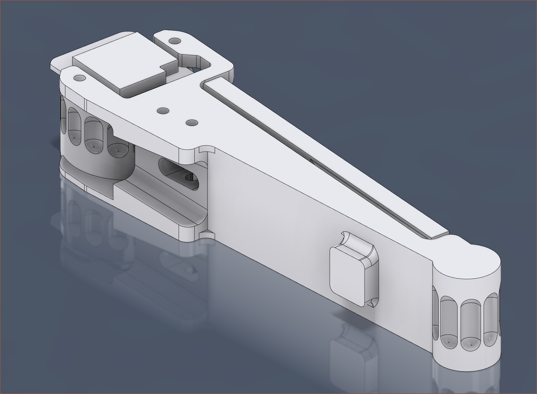
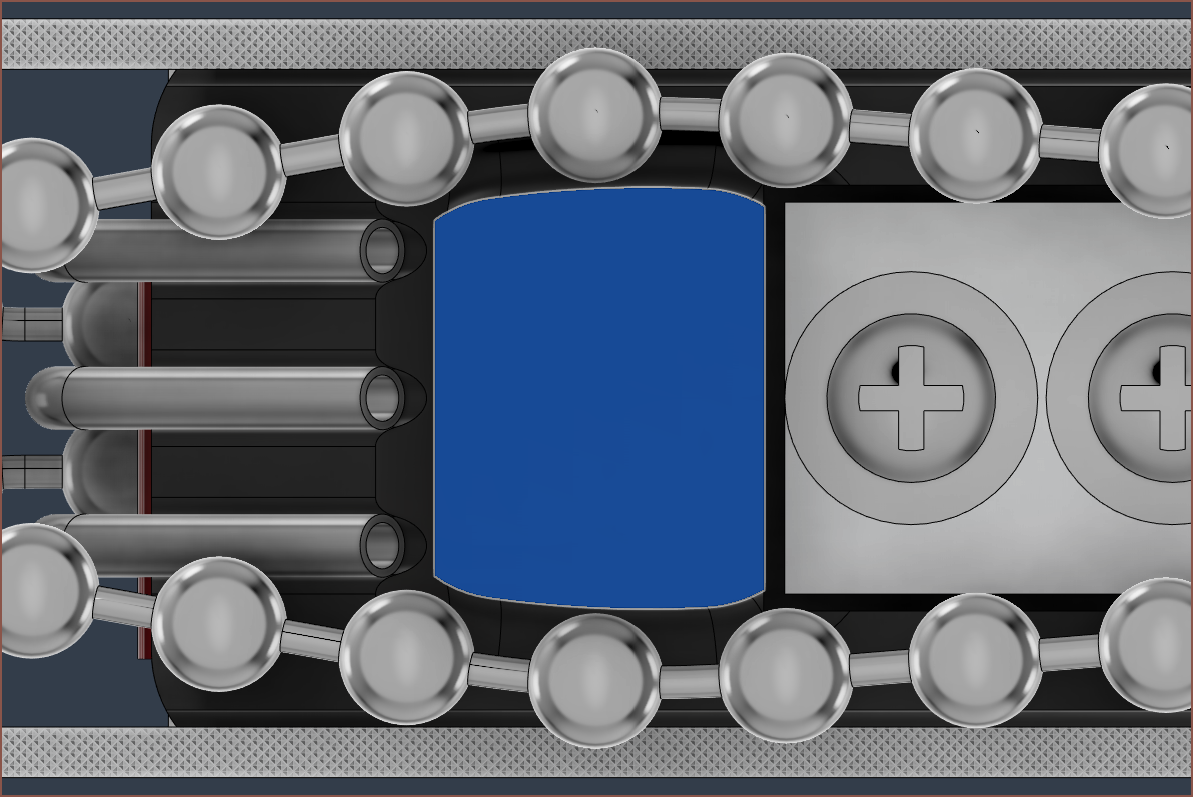
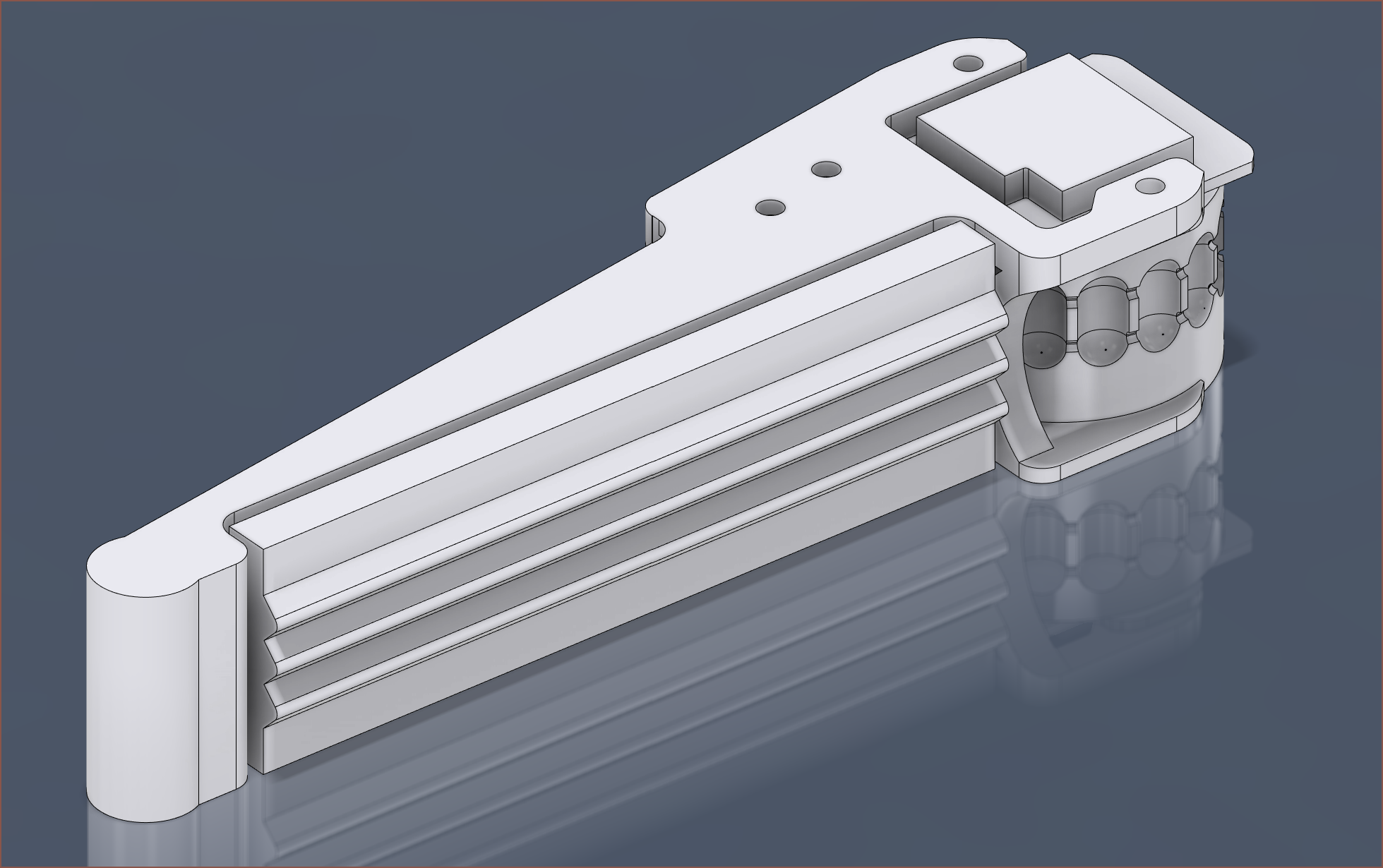
08/15/2023 at 20:08 • 0 commentsIt's not much, but it should give you a slightly better idea on how everything fits together. It seems that I've sketched the mirrored version of what I intended.
Also note that the bottom of the steel tubes are slightly closer together than the top, This is to give the ball-chains more space. The angle is only 2 degrees, which isn't significant enough to have 2 slightly different bending jigs. It's possible that I increase the angle should I need more space, but right now I've kept a 1.2mm gap for the walls of the printed part that holds these in place. The tubes also act as reinforcement for this printed holder.
-
[A] Interwoven Tetrinsic possible?
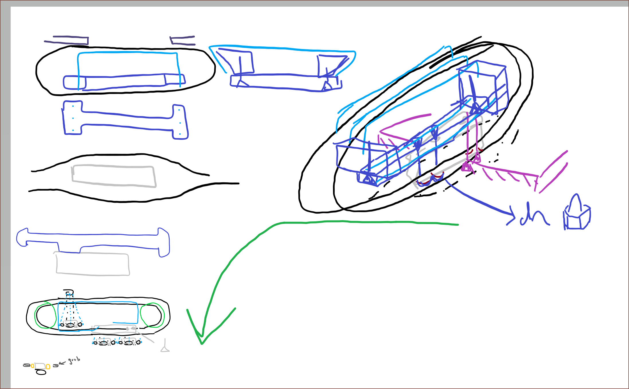
08/14/2023 at 00:13 • 0 commentsSince this new Tetrinsic now has 3D geometric considerations to uphold, I was having trouble thinking about the solution. Thus, I decided to create some rough sketches of the problem in Paint3D. Being able to digitally sketch to help solve problems is the main reason behind the Sketchθ mode in Tetent.
Initial Drafting
The design progression follows the green arrow. Basically, it was a bunch of drawings to figure out what could and couldn't go where, as well as making it easier to see how design decisions would propogate.
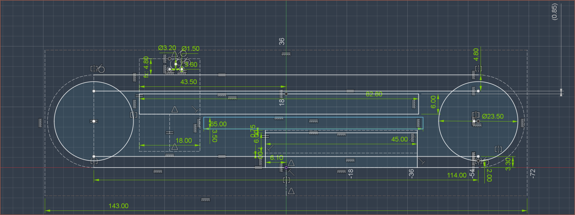
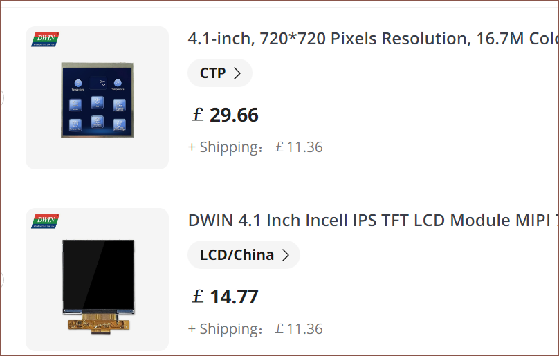
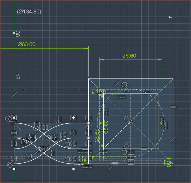
Once it seemed that I had an idea that could work, I continued the sketch in Fusion360 where I could get accurate scaling. It seems that 4.8mm is a good starting point as a Tetrinsic offset. I'm also planning for space for a 4.1 inch HMI, since it's almost the same dimensions as the panel by itself with the main difference being thickness.
As explained in this log, I believe the HMI is the best solution but it's also the one that uses the most space, thus if I can accomodate this display, I could later decide on going with any of the other solutions discussed instead.
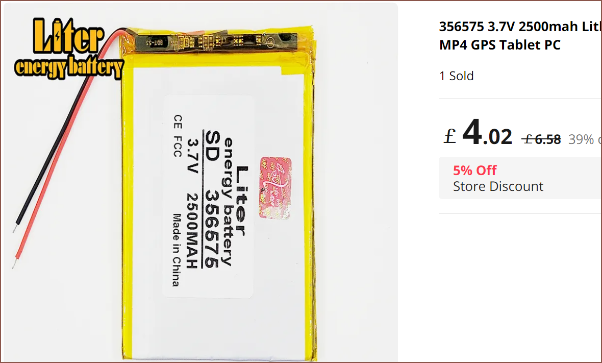
In the free space available, I've found this 356575, 2.5Ah battery:
To allow for enough space, I've gone with 17 teeth sprockets. The total height is thus 27.5mm. That's the same height as the TestTetrinsics I printed.
-
[T][P] Interwoven Tetrinsic? (and steel tubes arrived)
08/11/2023 at 12:40 • 0 commentsStarting yesterday, I've been conceptualising a way to get a fifth Tetrinsic to fit.
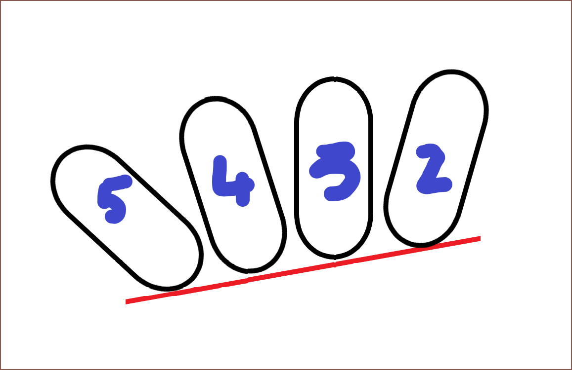
One of the ergonomic issues with Thumb1 is that it and Finger5 are both what I'd call "aligning fingers". As one would expect, the solution ergonomically fails if only one of them is in alignment. That's part of the reason why the main Tetent concepts have only used 4 fingers:
Left: Concept4, Center: Concept3, Right: Concept2. Wow, the 4th concept sure looks more futuristic than last years second concept. Unfortunately, any ergonomic solution failed geometrically due to the size of Tetrisic. #Tetent TestCut [gd0139] is no longer geometrically viable with how large Tetrinsic has grown now.
However, with this new idea that I talked about in the previous log, I feel that there's a possibility of obtaining one of the best ergonomic solutions possible whilst still being ergonomically viable, though it could be harder to manufacture since a closed loop would form around the FingerN Tetrinsics. The good news is that I can make it ambidexterous without needing an additional Tetrinsic, now that it's so long.
This strategy actually goes all the way back to this log here where there's even a handy diagram. Right now, I'm targetting a height offset of 6mm. Conveniently, the 1.5mm stainless steel tubes arrived. 1 tube alone already feels unmoving, so the 3 tubes that make up the sliding surface of Tetrinsic should be stiff enough for the task.
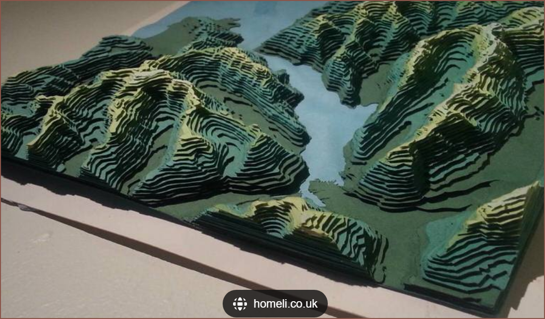
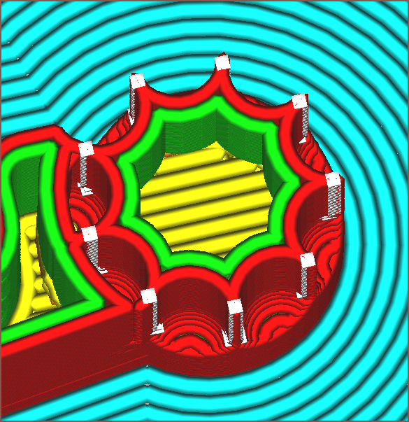
I'm also removing the LCD/Solar stuff from Tetrinsic. I'll still be keeping compatibility by exposing pins on Tetrinsic PCB, but it now seems that the aesthetic should be determined by the device that Tetrinsic is implemented in. For example, why have a small artisan keycap when the entire free area could be one, such as a topology map:
At the moment, I'm expecting the visible area to be about 75mm x 75mm for Tetent. This approach to lighting has come full circle, as the Tetwin Switches were designed to be transparent so that an external light source could shine though.
-
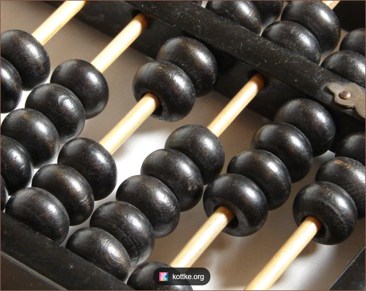
[E1][T] Tightrope / Abacus Inspired Concept?
08/09/2023 at 11:52 • 0 commentsSo, unfortunately, with the expected size of Tetrinsic, it's looking like a possible Tetent solution would be very similiar in dimensions to an AirBerry (my Let's Split keyboard), just rotated 90 degrees such that it's 6 rows, 4 columns instead of the other way around. I was imagining something like this:
It's... fine... simple yet modern... but it's not exactly the kind of device I hoped to get out of 19 months of R+D work.
However, just after writing about the linear motor research in the previous log, I thought of what a new Tetent could look like with one and thought of sometihng similar to this:
But then I remembered that a) the ball-chain of the current Tetrinsic runs on a stainless stainless steel tube, b) that tube is probably stiff and c) that a good part of the proposed Tetrinsic is empty space on the bottom half. Thus, why not turn the concept up-side down and bring back some level of future-modern, Apple-esque aesthetic that I'd expect to see on Yanko Design?
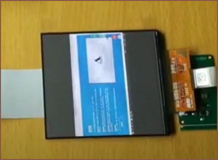
The most notable benefit of this is that a larger, single display could be used. However, as a larger screen means more pixels to drive, I'll most likely be sticking with the 2x 1.14" LCDs. Additionally, the only OLED I could find, the 3.8" one I was planning to use for #Tetent TimerSpy [gd0136], actually has poor black levels in ambient light. I can clearly see the difference between "black" on the OLED and the black bezels from this video
Another notable mention is that this extends to any material, such as a photovoltaic cell or a porcelain tile. Lastly, a benefit is that the pressure plates won't be right next to each other, meaning that I could actually have the Tetrinsics closer without worrying about manufacturing tolerances.
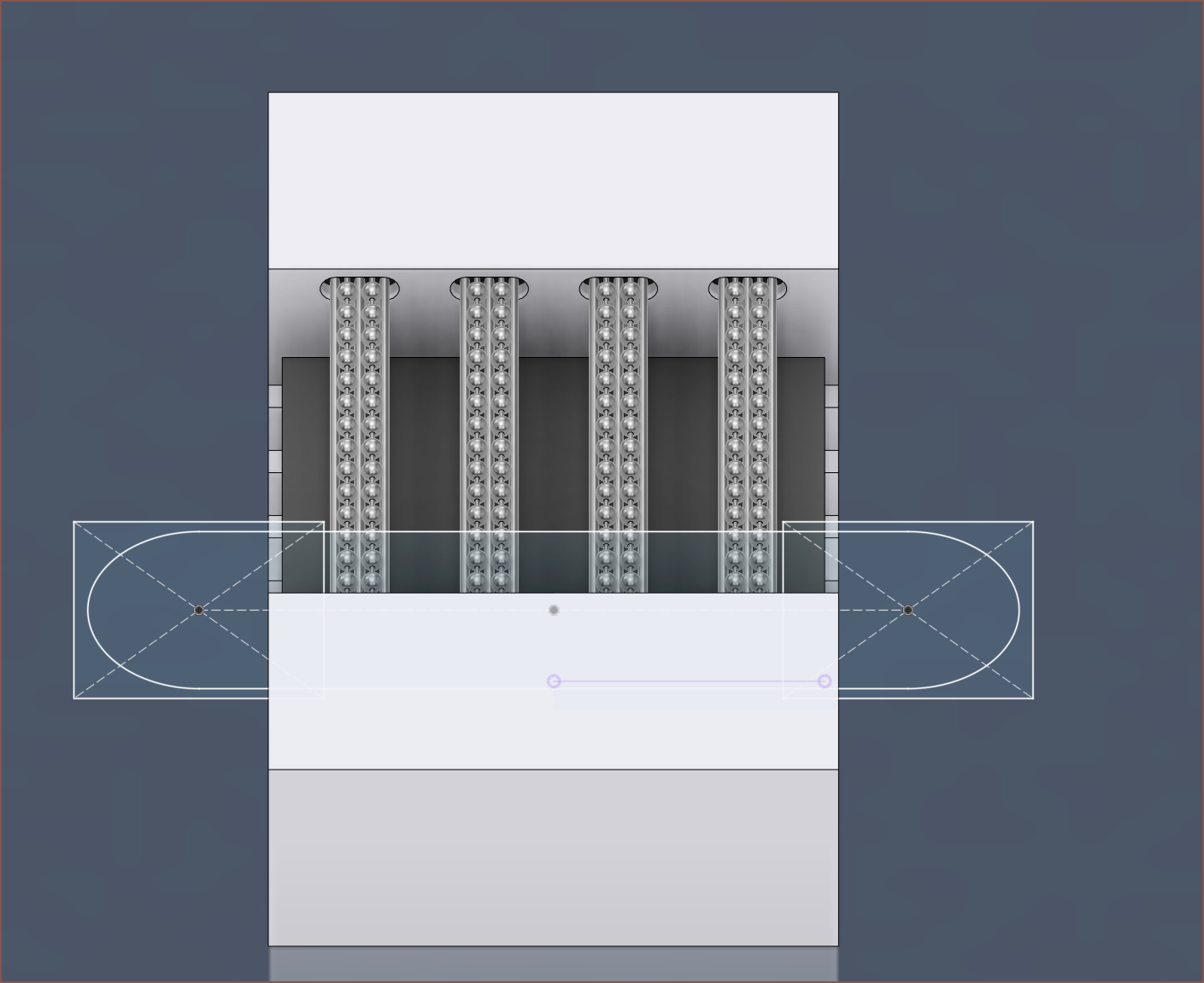
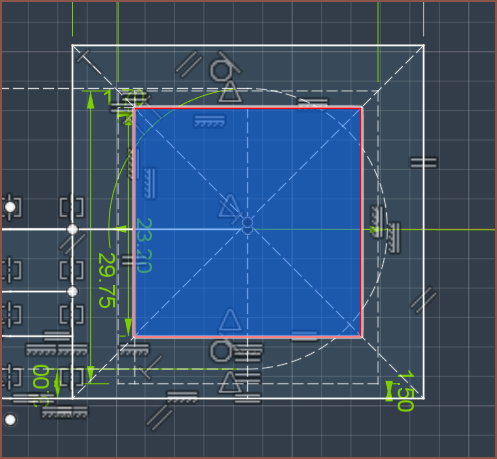
The next Tetent concept is currently a work in progress, but this sketch (which is one half) should give an idea as to the strategy I want to try. For starters, I'm thinking that the squiggly bit is where I could have a fancy design on the outside. Behind that, on the inside, it's where the load cell, battery and top screen would be. The square (highlighted below) is where the memory LCD would go, and the motors behind it.
Hopefully, this strategy makes the resulting Tetent designs look more futuristic, even if I might not be able to make Tetrinsic as thin as I'd like.
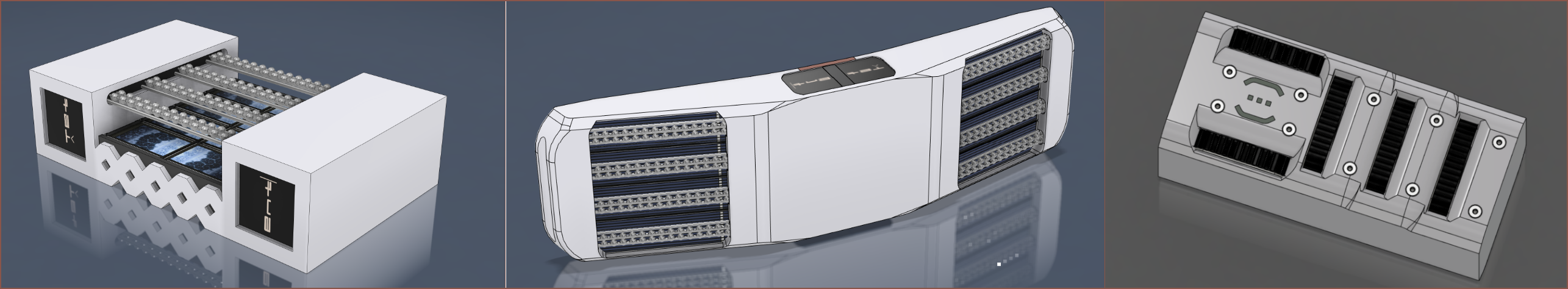
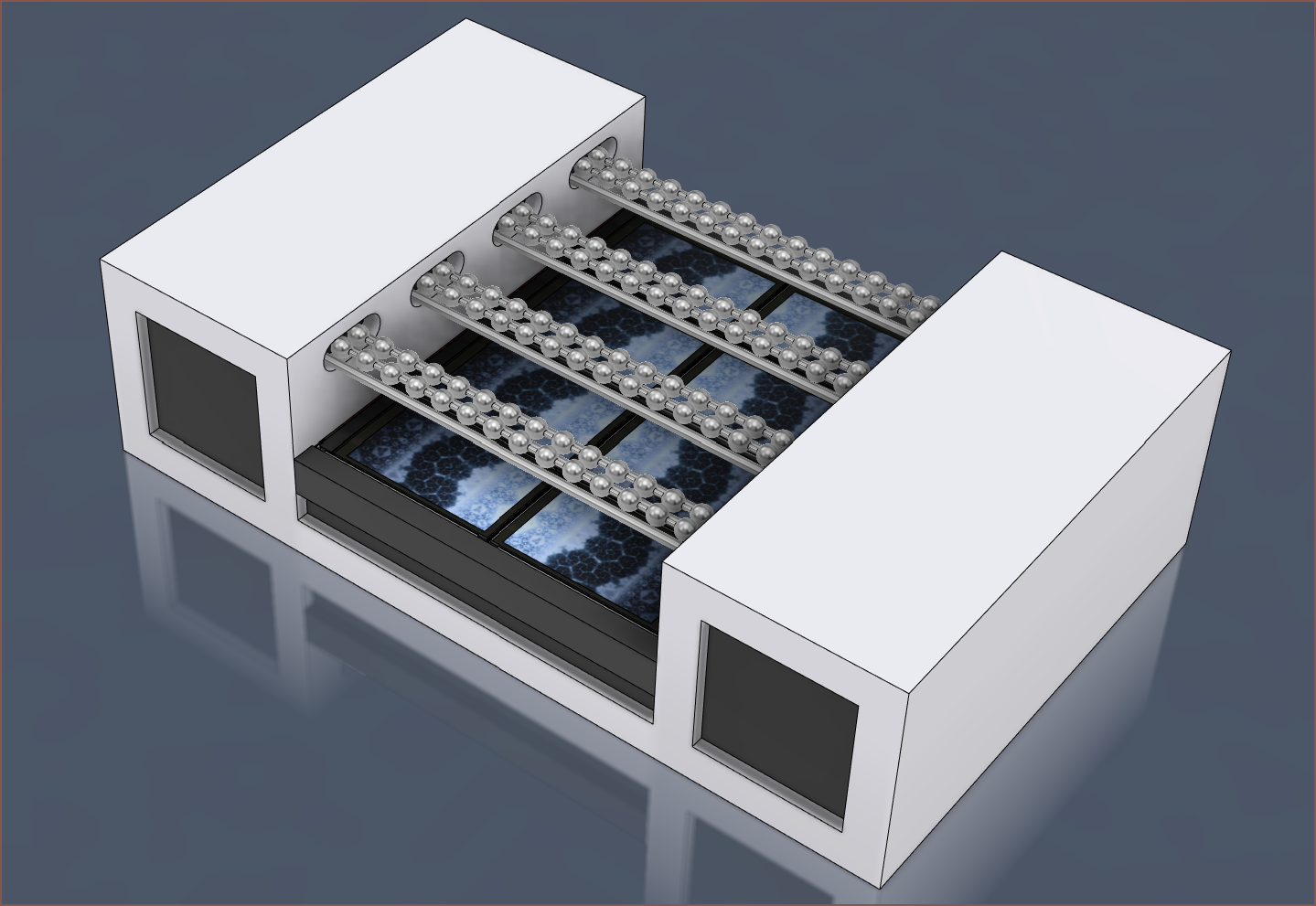
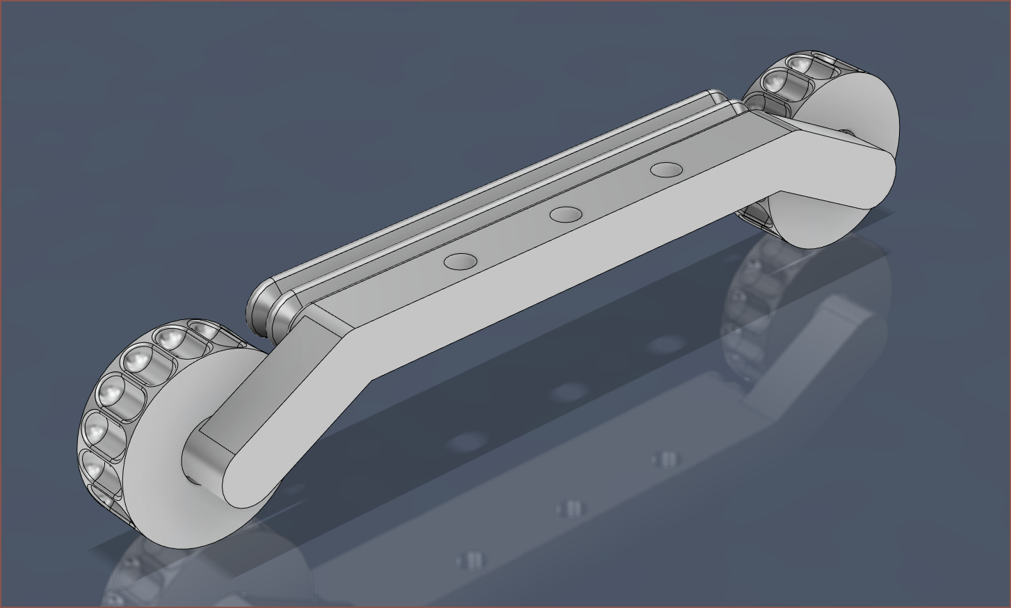
The 3D of the above looks like this, though I'll post updates on the overall design in the Tetent project:
-
[R] Linear Motor
08/08/2023 at 10:13 • 0 commentsAt this time of writing, I'm still going to go thorugh with the soon-to-be-designed dual motor Tetrinsic, but I'm still not happy about the length and height of the current solution. While the active length of 63mm makes sense as all 4 fingers can ergonomically exist in the resulting quad-Tetrinsic area, it only accounts for 54% of the total length. The thickness of 28-29mm is also limiting, and ideally Tetrinsic would be half this.
Other than width, the main ergonomic issue I need to engineer for is to obtain reliable fingertip grip whilst having a very low friction sliding surface, even when pressure in excess of 100gf per finger is applied.
To have a chance of meeting an under 15mm thickness target, a potential solition is to give up infinite-scroll and off-the-shelf hardware for a custom linear motor:
Unfortunately, I think the bigger issue is developing the software for Tetrinsic and mounting strategies, so right now I need a development solution and not an ideal solution.
-
[M][P] Solid State TestTetrinsic
08/06/2023 at 12:00 • 0 comments[13:00] Now that I've got a sprocket design that seems to grip the chain and I know what tolerances are likely acheivable, I started thinking about a possible test print I could use for a TestTetent. After letting my mind brew on some ideas over a couple hours, I'm going to first try and see if I can get something usable without any moving parts at all, and just have the ball chain slide over all surfaces.
The bottom has 4 M3 holes that are spaced 48 x 12mm apart, as I'm expecting the redesigned Tetrinsic to make use of integrated nuts in these locations. The holes in this model are self tapping since it's not like these test prints are going to be permanent.
The print is also 18mm thick, just like the expected real Tetrinsic.
While this concept is the largest yet, I'm hoping that there would be enough space for a thin battery that fits in the space available when 4 Tetrinsics are colinear.
[14:30]
The solution... failed.
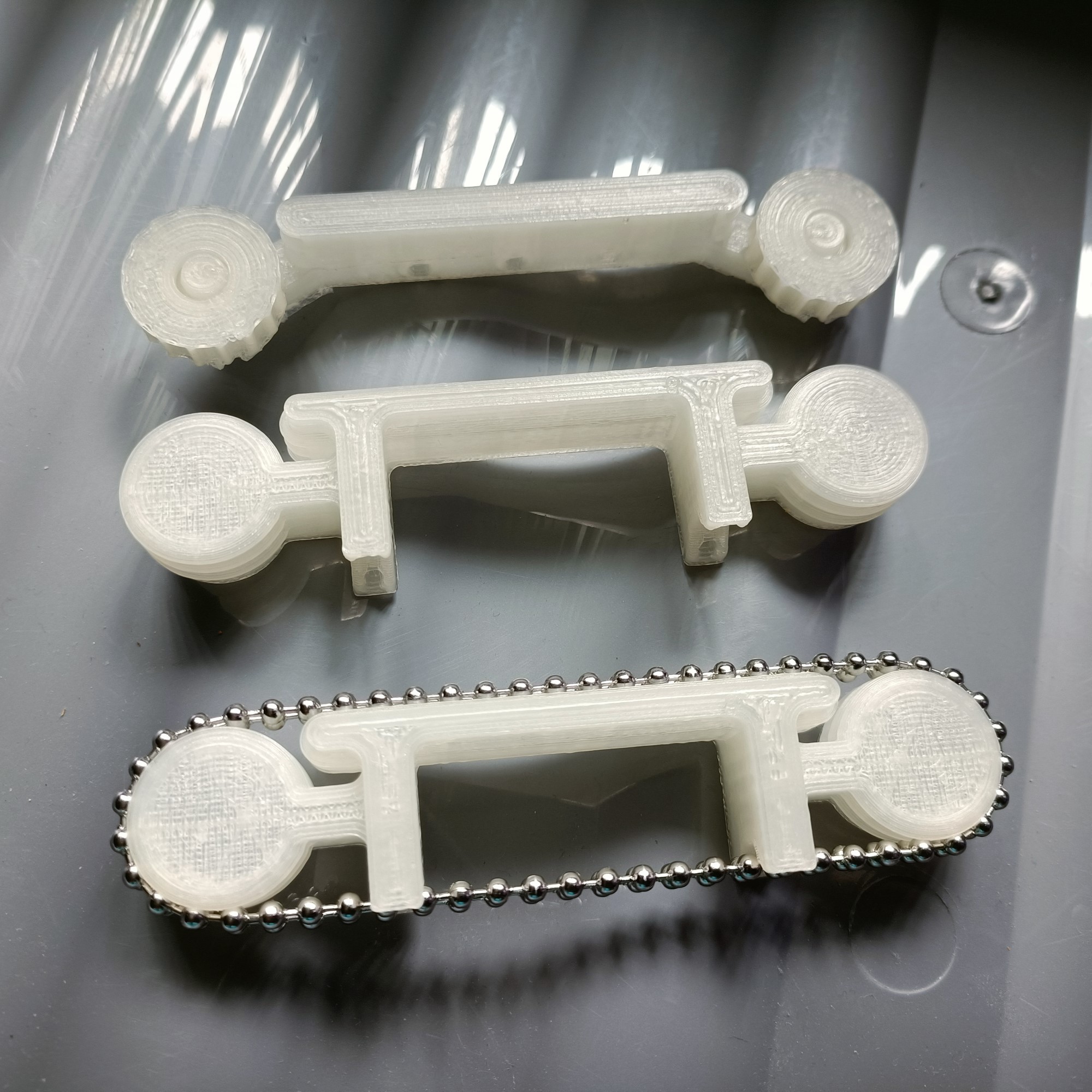
I printed out the first attempt and I was able to get the chain on but it was extremely tensioned. This was using 0 TensionOffset. The next print, which used 1.2mm TensionOffset, was suprisingly still tensioned but more manageable than the first attempt. The end-to-end length and height are 115.25mm and 28mm respectively.
The main issue with this solution is that the chains are free to independently slide, resulting in reduced comfort. Additionally, the friction resistance is quite high.
-
[E1][M][P] Test Tetrinsic
08/05/2023 at 14:42 • 0 comments[15:45] I've designed this print-in-place test part to obtain the correct chan fit before I start redesigning the main file all over agian. I'm also going to design for a less ambitious 4mm internal tube bend instead of 3mm as in the main file.
The hope is that I can subsequently print multiple of these and then test ergonomics of possible Tetent designs.
[17:00]
The first print is welded together, but it does seem that the first try tension equation of:
SprocketDistance = 20 * BallSpacing
has worked out ok. For a ball spacing of 20, there are a total of 21 balls between the tooth of the first and second sprocket (a.k.a 19 balls floating in air and 2 balls in contact with the sprockets). In the next print, I'm thinking of trying
SprocketDistance = 20 * BallSpacing - 0.2 mm
in an effort to aleviate any excessive stresses, as right now it's as tight as a tensioned GT2 belt. Not sure if that's good or if it'll mean I have issues with friction yet. This model has a length of 116.2mm, so I'd imagine that the final would be 116mm or less.
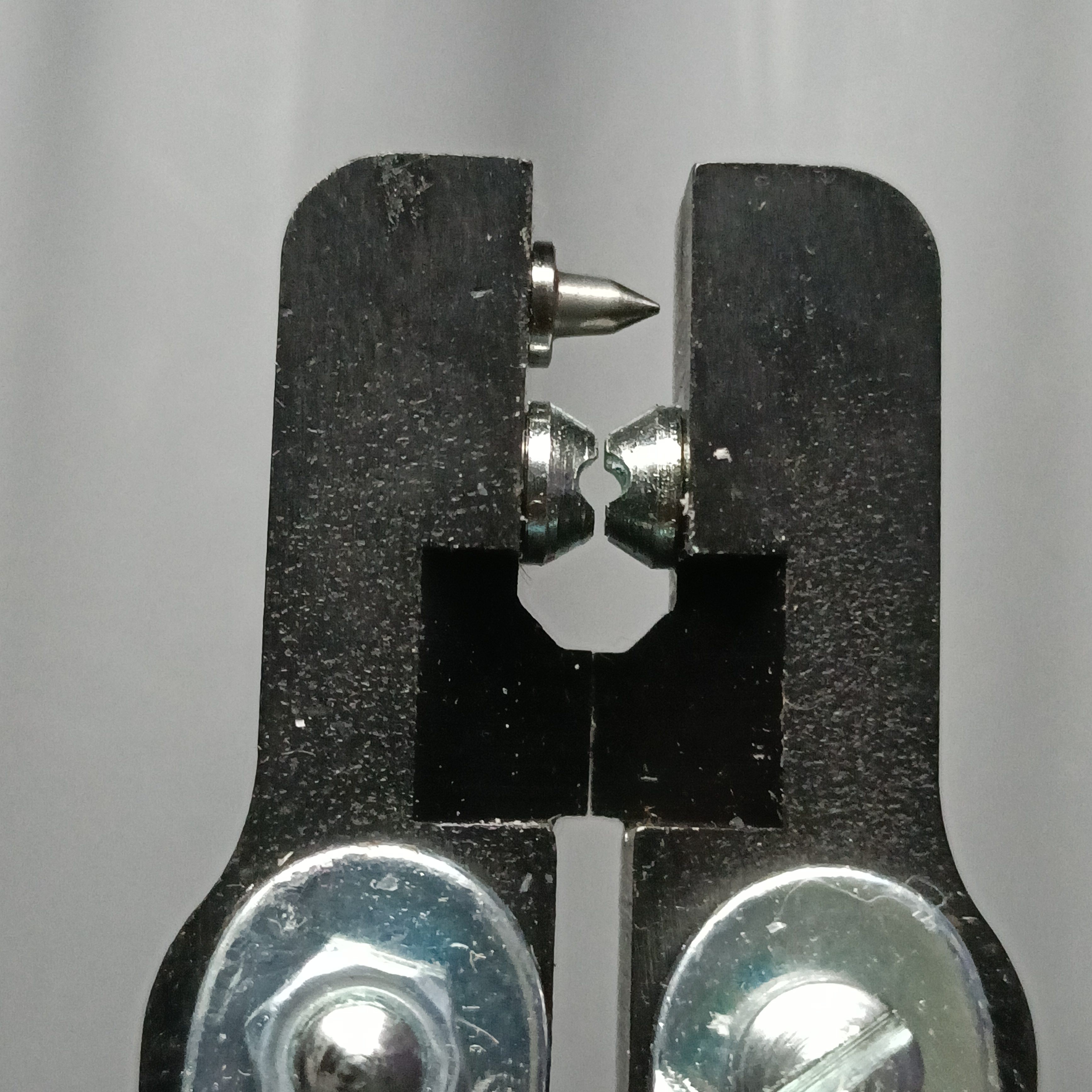
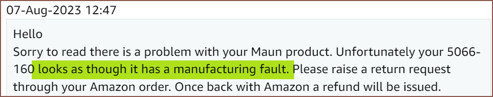
When I attempted to create the chain loop, I actually had one too many balls in the chain so I respliced it. Even though there are 2 reformed balls in the chain, it still seems sturdy enough. I'm not sure if this is just a limitation of the tool or another "Used, Like New" problem, but the ball dies on the Maun 5066 don't acutally meet and so the ball isn't completely closed.
[7 Aug: Edit 1] It has been identified by the seller as having a manufacturing fault.
[/Edit 1]
This time, I'm going to print this upside down to see if I can avoid first layer squish issues:
If anything, it'll give me a chance to improve my support settings.
[18:20]
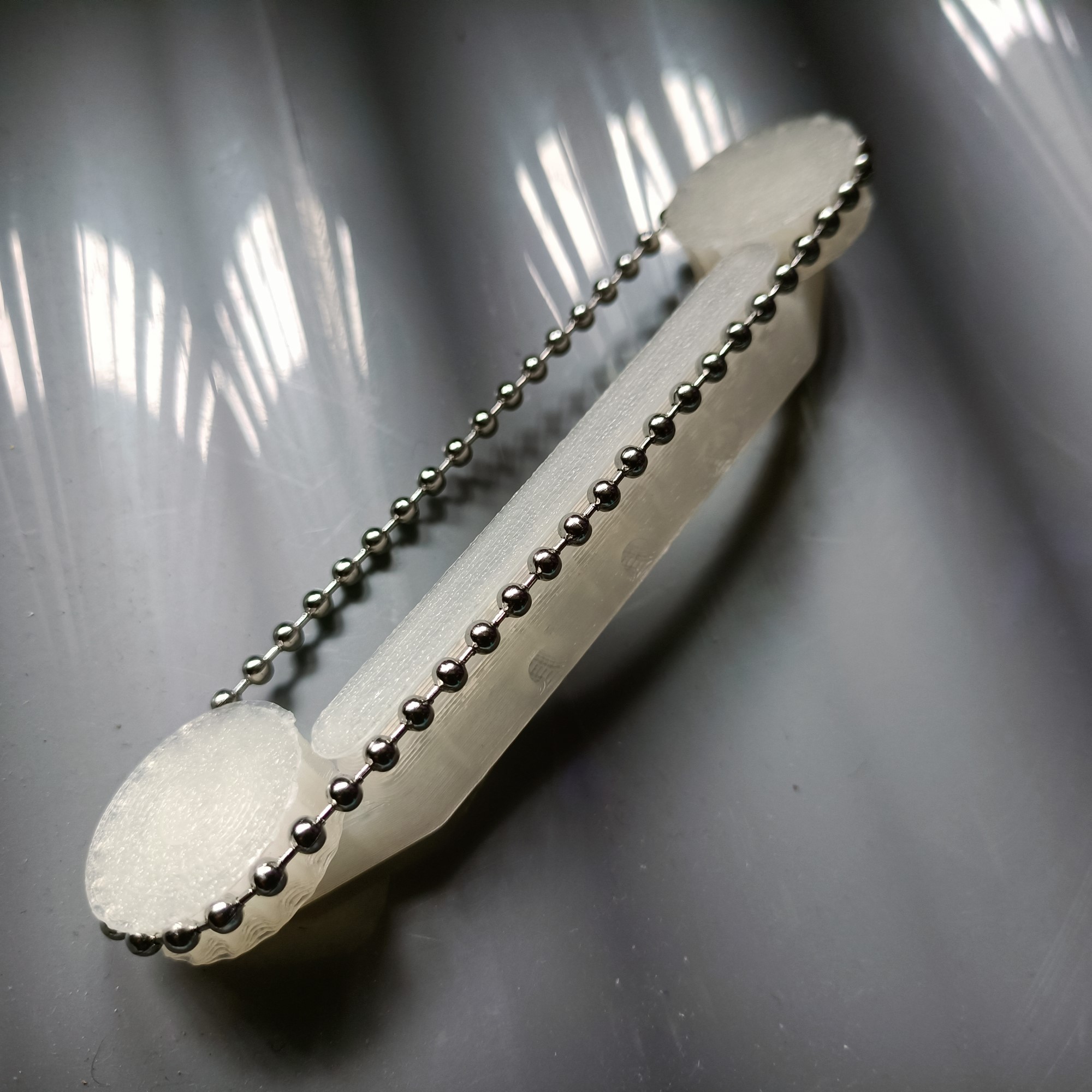
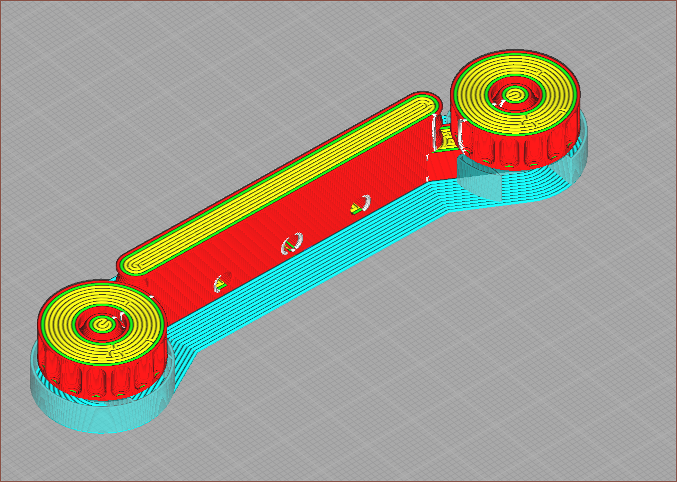
Shame how Tetrinsic is turning out longer and taller than I'd like. As expected, the undersides of the sprockets are rough, but it actually spins now, albeit with quite some resistance. The full length is now 115.7mm. Now to figure out how much of an offset I can get away with.
- The sprocket with the ball chain is 26.2mm, the sprocket by itself is 22.0mm (it was modelled as 22.2mm).
- The full length without the chain at all is 111.8mm, though it's supposed to be 113.0mm.
- This can be explained to the looser tolerance, as the first attempt was 113.4 modelled, 112.8mm on calipers.
- The above 2 bullet points imply that the chain sticks out of the sprocket by approximately 2mm.
- Not sure how relevant that number is to this calculation, but it's nice to know.
- The chain is still taught on the second print even though it's 1mm shorter than the first one, so perhaps I don't need a super critical tolerance and can just design a fixed length solution.
- It does feel slacker though.
- I guess a refined equation is probably the equation below:
SprocketDistance = (Ball_Amount - 1) * BallSpacing - TensionOffset - 0.6 mm
- JLCPCB is likely to make the parts much closer to the CAD model than my Linear Plus FFF 3D printer, so that's what the "- 0.6mm" part of the equation is.
- Since the first print was probably the max achievable tension and the second print is closer to the minimum, I'll assume that the range of TensionOffset is from 0 to 1.2mm. Thus, if I use an offset of 0.6mm, I'd have ±0.6mm of tolerance to work with. However, it's likely to be in my best interest to have a TensionOffset closer to 0 than 1.2mm.
Ok. Noted.
Another thing to note is that this design uses 56 balls a chain, but I have to cut 57 balls off the 5m length. Thus, the length required is as follows:
1 Chain:       4.55mm   * 57 = 259.35mm
1 Tetrinsic:   259.35mm * 2  = 518.70mm
8 Tetrinsics:  518.7mm  * 8  = 4.1496m (appx. 4.15m)
10 Tetrinsics: 518.7mm  * 8  = 5.1870m (appx. 5.19m)
It's a good thing that stainless steel ball chain is relatively cheap. Shame it gets negated by the price of the splicing tool though. Hopefully there's some AliExpress seller that sells varying closed loop lengths of ball-chain similar to the many that sell closed GT2 belt lengths.
-
[T] Minimum radius issue!
08/03/2023 at 19:39 • 0 commentsThe current solution... may fail, due to: - turning radius requirements of the 3.2mm ball chain approaches the motorised sprocket diameter.So I've implemented some tweaks and learned a few things.
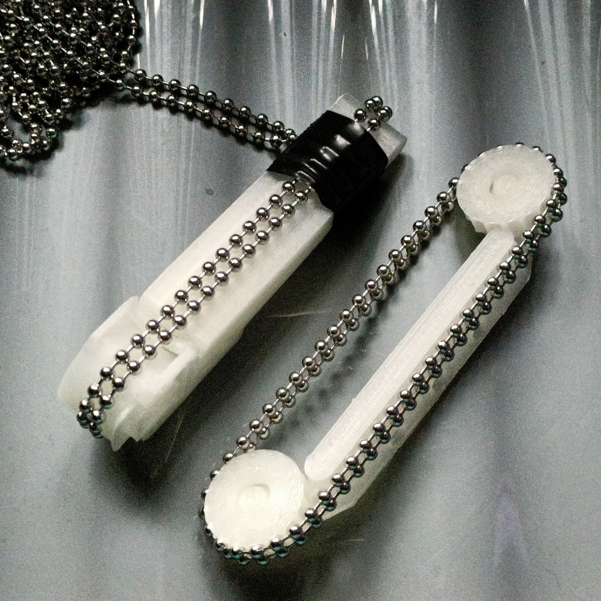
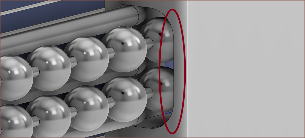
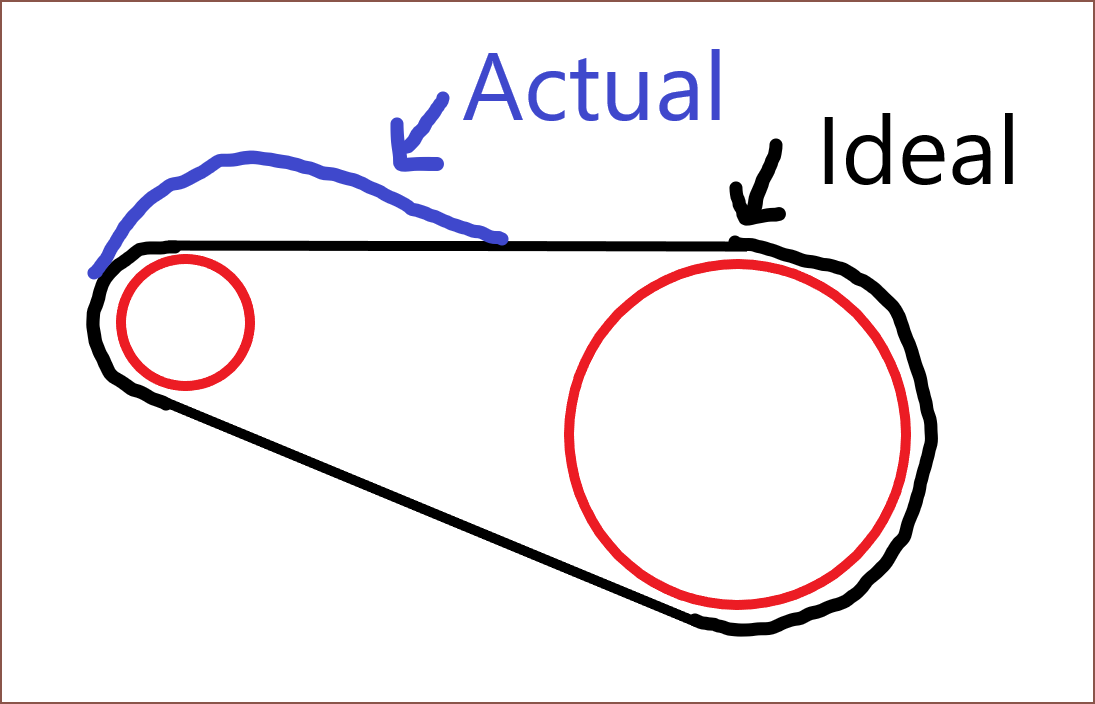
Firstly, unlike what I assumed months ago, the chain won't actually slot into the sprocket teeth if the teeth are too close together. Instead, the first and last balls slot in and the rest kind of hover in an arc:
Purple is expected and red is actual. Secondly, its starting to seem that the 3.2mm chains natually tensioned turning radius is closer to the 16 teeth motorised sprocket than the 10 teeth unpowered front sprocket. It kind of makes sense now that I've actually got prints in my hand and the small bend does seem ambitious. This issue might be mitigated since there'd be a roof over the sprocket, but what is likely to happen is that the chain catches on the top edge of the entrance hole (see below), especially when in different orientations.
Taking costs and utility into account, it would overall be more beneficial to use dual motors. I know what I'd need to change in the file, but there's quite a few changes that would need to be made. I'll also have to assume that I need to be able to spin up the motors so that I can get both sets of poles aligned before I lock their rotations together via the chain.
The bigger issue is that the solution would cause the current Tetent concept to fail, mainly due to Finger5 as per usual. Sorry Me In The Past, but it is not safe to upgrade now.
-
[E1][M] Front Sprocket
08/03/2023 at 12:24 • 0 commentsAfter considering my options, I've decided to continue trying to obtain a solution with 3.2mm ball chain. I've now modelled the front sprocket solution. I've spaced the front and back sprockets to be an integer spacing appart (I think 20 balls) and I've designed the front sprocket in such a way to ensure that the chain stays in the tube track throughout the length.
I'm somewhat hoping that I can use the pressure plate to tension the chain due to the deviation from a straight line from sprocket to sprocket.
This is what the printable mockup looks like:
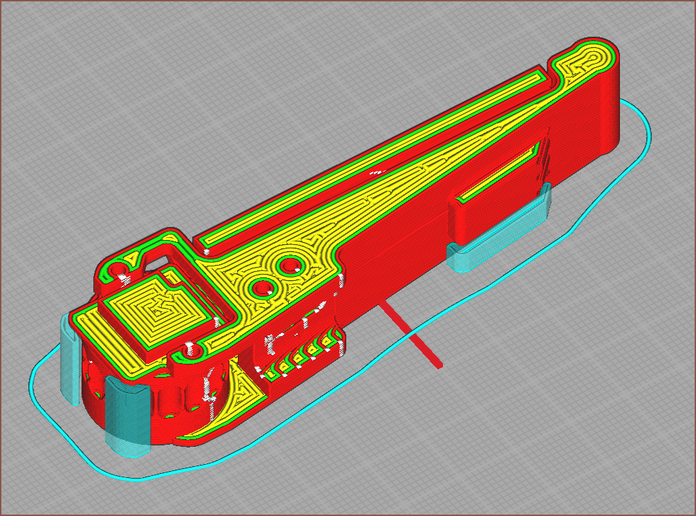
[15:15] I printed the above and I knew something was suspicious when the Cura preview looked like this:
Those white squares are retractions. Essentially, those spikes have become all blobby when printed, so I knew I had to fix that and reprint. I also have to keep in mind that even professional SLS 3D printing a minimum wall thickness so I need to prevent the ends getting too thin. I've now added a special fillet to both sprockets:
Another thing I noticed is that the chain weakly caught onto the corners, so I've made the extrusion more cylindrical:
-
[M][P][T] Printable Concept
08/02/2023 at 13:04 • 0 comments[14:05] Now that I've got some way of splicing some loops, I can start printing out a concept so that I can obtain the correct tension required. One of the drawbacks of this design is that there isn't any way of adjusting chain tension and ball-chains themselves would be rather inflexible. I can only assume a 3rd pulley, connected via a flexure of some kind, would allow for looser tolerances in this regard.
The first print attempt is currently being printed as I type.
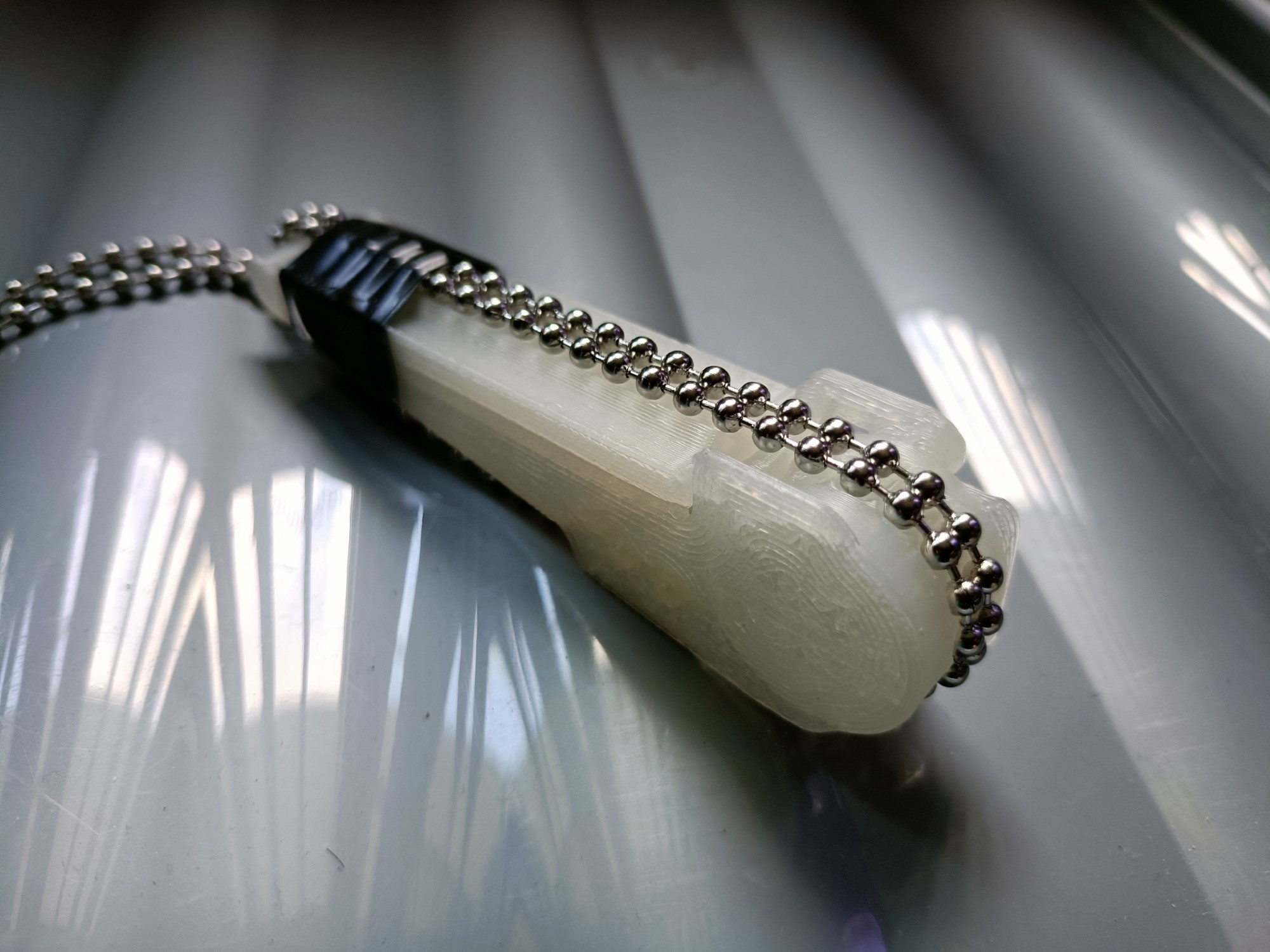
[18:00] So I used tape to hold the ball chain onto the print without even needing to splice anything. Looking back, I probably should've tried this weeks ago.
The good news is that it looks like the renders and it seems to work well with my fingernails; I actually have grip instead of the ice skating my fingers have to contest with on keyboards. Finger5, which seems to approach at an angle almost 45 degrees from the normal, seems to have rather good grip.
This is what it looks like when I grab my latest Tetent concept with my right hand, such that my palm is facing me. If slippage does occur, I think it feels more comfortable than a GT2 belt. The chain does sit inside the sprocket, but I think I'm near the limit before I need to add another tooth. Additionally, it seems that the chain doesn't leave the track when this Tetrinsic mockup is in varying orientations, such as upside-down. When my eyes are closed, it's easy enough to feel where the center of the chains are.
The bad news is that it seems that the chain won't make the 8mm diameter pulley bend without significantly lifting from the track (see below), as well as the understandable fact that the difference between tensioned and loose seems to be on the order of fractions of a milimeter.
I can't tell if I've engineered myself into a corner or if someone else designing a motorised, pressure sensitive linear slider would come to the same general design (e.g. a computer mouse having at least a left / right click button and a scroll wheel). The main requirement really is that Tetent works for me, not the other way around, thus that's the reason why a tangible requirement for Tetrinsic was natural fingernail compatibility; I didn't want to meticulously trim them (and lose out on their benefits in day-to-day life) just so I can type.
It doesn't help that the current best option for splicing is a £90 tool, but if Tetrinsic ever got popular enough, there'd be some AliExpress seller selling prespliced chains and so the tool cost would be a non-issue. I'm not sure if the issues discovered are showstoppers or not, but until I have something manufacturable, having to restart from square 1 is still a possibility.
Tetrinsic [gd0041]
A continuous, motorised fader that is force sensitive and haptic.