Mrinnovative
DC-motor-speed-control-circuit-using-IC555-TIP122

Pulse Width Modulation PWM controller. PWM is a technique in which the amount of current going in a circuit can be controlled by
chopping the Direct current using a gate or transistor that is changing its duty cycle( on-off time) you should see this article flashing of LED using 555 IC.
This article is about how you can control the speed of a DC motor using PWM motor controller
This PWM circuit can be easily found in our daily life equipment like mobile chargers, laptop adapters, inverters
the power supply of desktop pcs, and in many other types of equipment in which steady low voltage is required.
We use DC motors like DC fans in many systems in our daily life. For example, to cool the system, in power supply, etc. Most of the time we have to control its speed according to the requirement.
There are many ways to do it. For example by inserting a series resistor to limit the current and hence limit the speed.
But this is not a good way because in doing so, much of the power is wasted in the form of heat.
If we use any microcontroller, then this is an expensive method that is not affordable and suitable for small motors.
That’s why we use PWM which has high efficiency and accuracy.
COMPONENT USED
555 Timer IC
TIP122 NPN transistor (You can also use MOSFET IRFZ44N)
1N4007 diodes (3no)
5-mm LED
1k 0.25-watt Resistors (3no)
10k 0.25-watt Resistors (1no)
100k Potentiometer (1no)
100nF Capacitor (C2) (1no)
10nF Capacitor (C1) (1no)
Connectors
Custom PCB
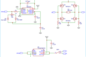
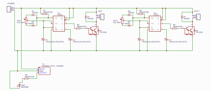
CIRCUIT DRAWING
To control the speed of the motor, we have to control certain electrical parameters that directly affect its speed. Obviously, we have to adjust the voltage and current supplied to it.
One way is that at constant supply voltage, you might want to put a variable resistor(potentiometer) in series with the motor to adjust/limit the current that it draws during operation. The bad thing about this method is that by limiting the current flow changes the value of the series resistor which also changes the voltage across the motor. When the motor is loaded, it draws a significantly large amount of current thus increasing the power across the series resistor. The power across the resistor will just be converted into wasted heat.
Another way is to use a Common emitter bjt transistor configuration with the motor as the load to adjust the current through the motor by changing the supply voltage at the base-emitter junction of the transistor. However, this is harder to predict since the relationship between the Vbe and Ic of the transistor is exponential. Aside from additional transistor concepts that you have to keep in mind, the transistor itself dissipates additional power as heat.
Another alternative and probably the most popular among speed control methods is the pulse width modulation. This method generates a pulse signal of voltage or current switching from on(HIGH) and off(LOW) with definite intervals on each state and a defined constant frequency overall. Note that this kind of voltage signal would still look like a constant DC voltage as seen by the motor. If you supply a DC motor with a 9V source and a switch but you constantly press the switch between On and Off reduces the average voltage supply as seen by the motor thus reducing its speed.
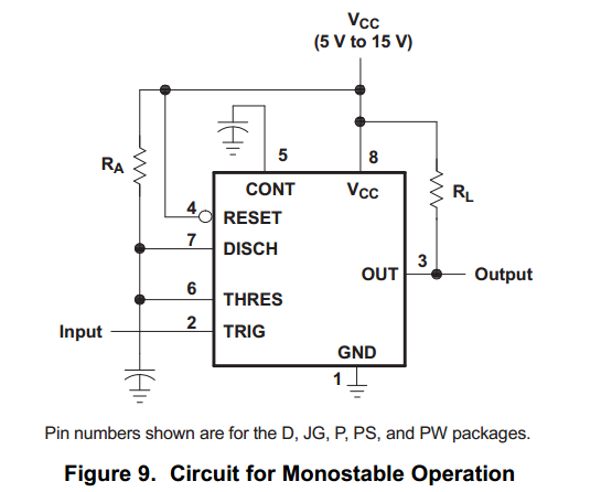

The 555 timer IC is a monolithic timing circuit that produces accurate timing delays and oscillations in a form of a square wave signal. This small IC has a lot of applications such as in oscillators, tachometers, waveform generators, control systems etc. Some features of 555 timer ICs are:
-It operates from a wide range of power supplies ranging from + 5 Volts to + 18 Volts supply voltage.
-Sinking or sourcing 200 mA of load current.
-The external components should be selected properly so that the timing intervals can be made into several minutes along with the frequencies exceeding several hundred kilo hertz.
-The output of a 555 timer can...
Read more »
 Osman Mazinov
 ElectronicABC