Lithium ION
Hello guys, I want to make my own most accurate temperature meter. When coming to the high temperature measurements, PT1000, PT100 and K-type thermocouple can be the solution. But the problem is big and messy wires between the Microcontroller and sensor. These wires are not waterproof and heatproof. The analog sensors are not too much accurate and take a long heat-up and cooldown time.
So, keeping all the factors and requirements in mind. I decided to go with MLX90614 Infrared Contact-less temperature sensor. This infrared sensor can measure outer body temperatures by receiving infrared heat emitted from body or surface of object. Then we will convert this project in PCB project as the commercially available one. PCBWAY is the best PCB prototype service providing Company. And if you Sign-up using my link, you will get free coupons and newcomer gifts.
MLX90614:
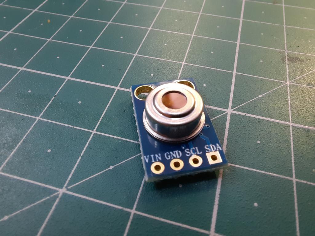
The MLX90614 Temperature Sensor is capable of measuring the temperature of a particular object or surface without getting into contact with it. The sensor works measuring the amount of IR light emitted by an object towards which it is pointed at, it uses the principle of Stefan-Boltzmann Law which states that all objects including living being, emit IR energy based on the temperature of the object or the being. Hence by measuring the IR energy emitted, we can calculate the temperature of the object.
Features:
· Operating Voltage: 3.6V to 5V
· Operating Current: 1.5mA
· Temperature Range: -70°C to 382.2°C
· Accuracy: 0.02°C
· Package: TO-39
· When measuring the temperature, please maintain a measuring distance of 1 cm
· Small size, low cost
· Factory calibrated in a wide temperature range: -40 to 125 C for sensor temperature and -70 to 380 C for object temperature.
· Customizable PWM output for continuous reading
Working of Infrared thermometers:
Similar to visible light, it is also possible to focus, reflect, or absorb infrared light. Infrared thermometers employ a lens to focus the infrared light emitting from the object onto a detector known as a thermopile. The thermopile is nothing but thermocouples connected in series or parallel. When the infrared radiation falls on the thermopile surface, it gets absorbed and converts into heat. Voltage output is produced in proportion to the incident infrared energy.
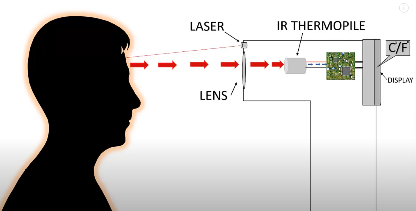
The detector uses this output to determine the temperature, which gets displayed on the screen. While this entire process may sound complicated, it takes only a few seconds for the infrared thermometer to record the temperature and display in your desired unit.
Emissivity:
Emissivity shows how much infrared energy a thermometer can put out at a time. IR thermometers with emissivity closer to 1.00 can read more materials than those with lower emissivity value. Pick a thermometer that comes with an adjustable emissivity level to tweak the amount of infrared energy emitted and compensate for the energy reflected by the material in consideration for temperature measurement.
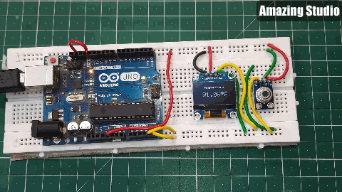
Components required:
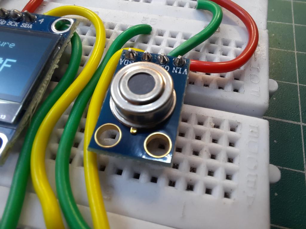
1) MLX90614 temperature sensor
2) Arduino Uno
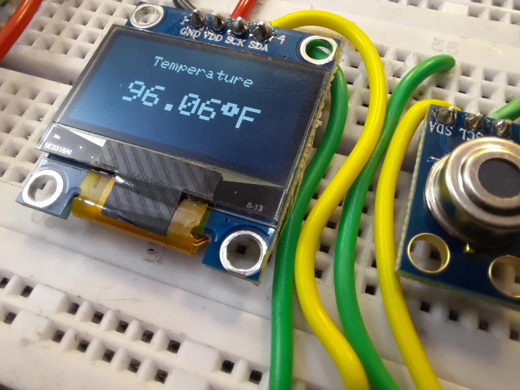
3) SH1306 Oled
4) Breadboard or Custom PCB
5) Wires and soldering equipment’s
Circuit diagram:
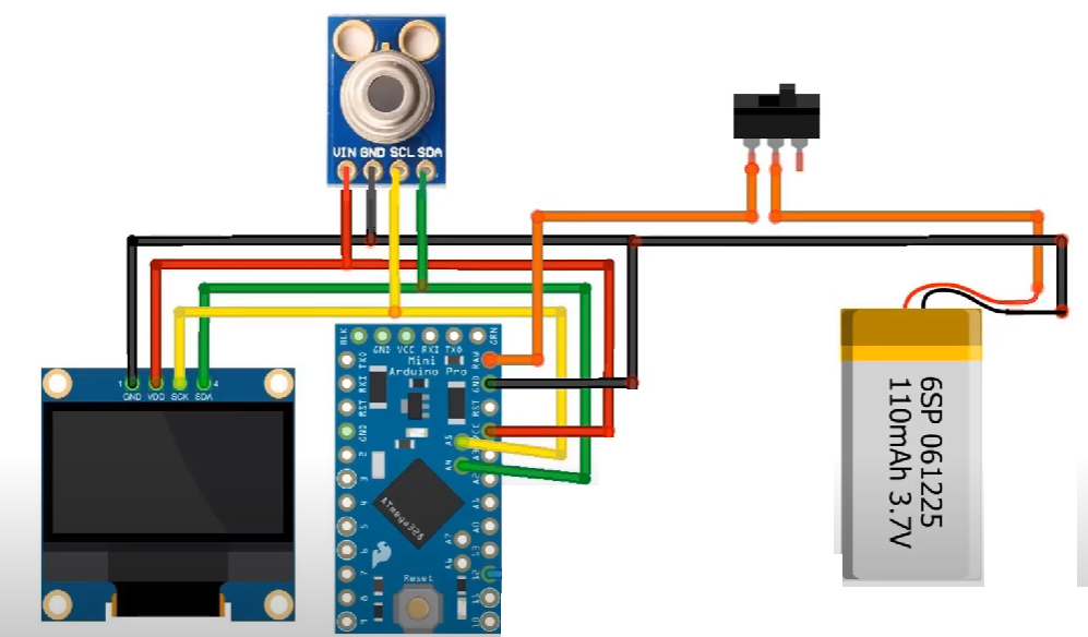
Here in the circuit we are using very minimal components, A screen to print the readings, MLX sensor and Arduino as brain of this project. Arduino has SDA and SCL pins A4 and A5 respectively. We can connect both Led and sensor using I2C protocol to that SDA(DATA PIN) and SCL(CLOCK PIN). I2C can support up to 127 devices, here we have only two. All the circuit is powered by 5volt Dc.
PCB layouts:
Keeping the size of project in mind, I designed a PCB. Here we are using Arduino nano chip and type c port to power up the whole system. You can also place a boost converter with 3.7volt battery.
Download PCB files, Gerbers and schematics from here.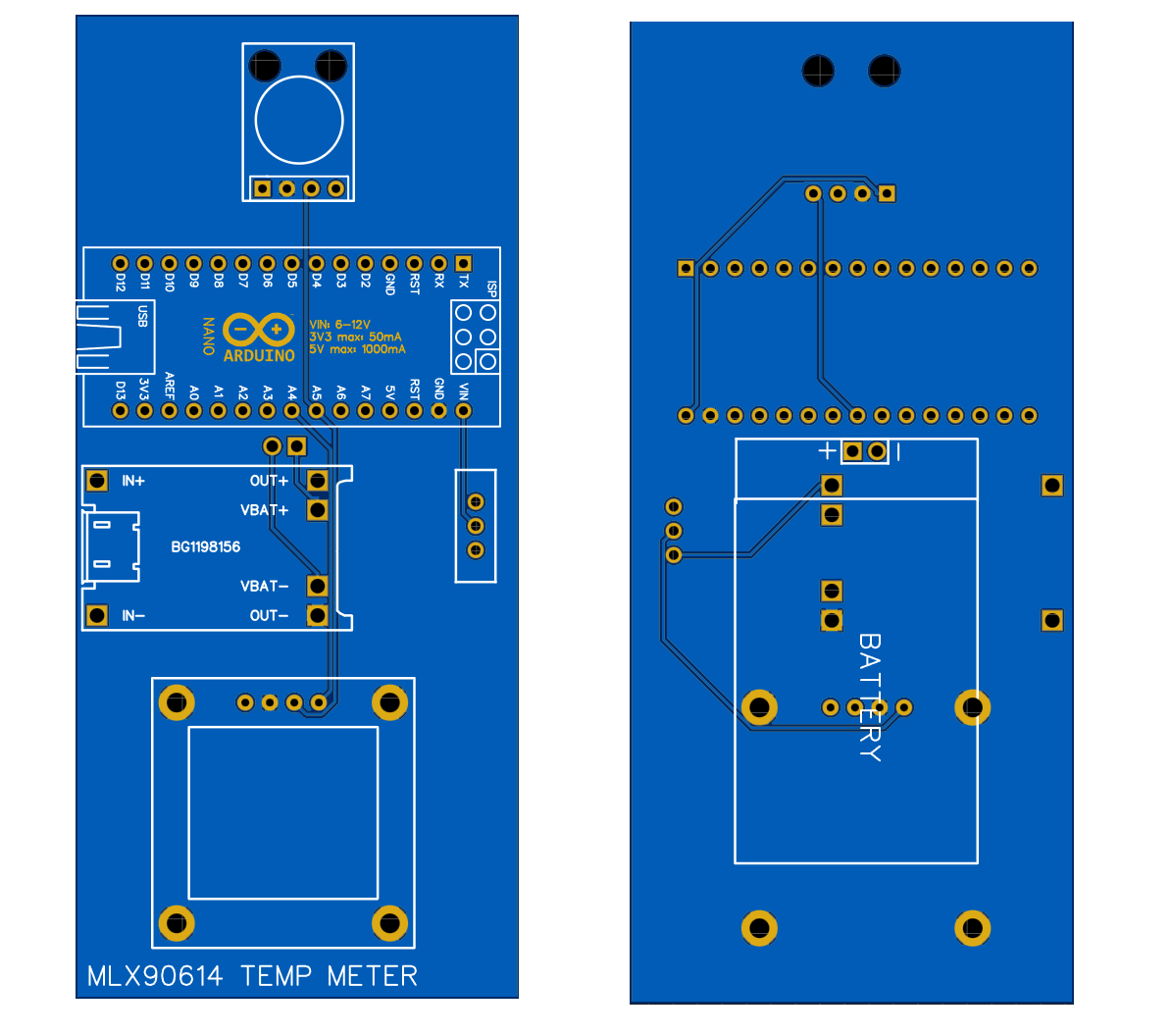
PCBWAY is the leading PCB manufacturing company for electronics hobbyists and project...
Read more »