 Epsilon
-
A C Standard Library for BoxLambda.
11/07/2022 at 14:13 • 0 commentsBoxLambda is a hardware-software cross-over project (see About BoxLambda). The previous posts have been mostly about hardware (as far as FPGA logic can be considered hardware). This post will be about software for a change.
I would like to bring up the C standard library on BoxLambda. Having a standard C environment will help with the overall platform bring-up. It also allows us to run third-party C code, which typically assumes the presence of a standard C environment.
Recap
This is a summary of the current state of BoxLambda. We have:
- A test build consisting of an Ibex RISCV core, a Wishbone shared bus, a Debug Core, internal memory, a timer, two GPIO ports, and a UART core.
- A simple Hello World and LED toggling test program running on the test build.
- An Arty-A7-35T FPGA version of the test build.
- A Verilator version of the test build, for a faster development cycle and automated testing.
- OpenOCD-based Debug Access to the system, both on FPGA and on Verilator.
- A Linux Makefile and Bender-based RTL build system.
Picolibc
I’ll be using the Picolibc standard C library implementation. Picolibc is a Newlib variant, blended with AVR libc, optimized for systems with limited memory. Newlib is the de-facto standard C library implementation for embedded systems.
Building Picolibc
I created a Picolibc fork and added it as a git submodule to BoxLambda’s repository: sub/picolibc/.
Picolibc Configuration Scripts - RV32IMC
A Picolibc build for a new system requires configuration scripts for that system in the picolibc/scripts/ directory. The scripts are named after the selected processor configuration. They specify such things as the compiler toolchain to use, GCC processor architecture flags, and CPP preprocessor flags tweaking specific library features.
I’m using RISCV ISA-string rv32imc as the base name for the new scripts I’m creating. This corresponds with the default -march value of BoxLambda’s GCC toolchain:
riscv32-unknown-elf-gcc -Q --help=target
The following options are target specific:  -mabi=                                ilp32  -malign-data=                         xlen  -march=                               rv32imc  -mbranch-cost=N                       0  -mcmodel=                             medlow  -mcpu=PROCESSOR  -mdiv                                 [disabled]  -mexplicit-relocs                     [disabled]  -mfdiv                                [disabled]  -misa-spec=                           2.2  -mplt                                 [enabled]  -mpreferred-stack-boundary=           0  -mrelax                               [enabled]  -mriscv-attribute                     [enabled]  -msave-restore                        [disabled]  -mshorten-memrefs                     [enabled]  -msmall-data-limit=N                  8  -mstrict-align                        [disabled]  -mtune=PROCESSOR
  Supported ABIs (for use with the -mabi= option):    ilp32 ilp32d ilp32e ilp32f lp64 lp64d lp64f
  Known code models (for use with the -mcmodel= option):    medany medlow
  Supported ISA specs (for use with the -misa-spec= option):    2.2 20190608 20191213
  Known data alignment choices (for use with the -malign-data= option):    natural xlen
The easiest way to create the new scripts is to derive them from existing scripts for similar platforms. I derived the rv32imc configuration files from the existing rv32imac configuration files:
- do-rv32imc-configure is based on do-rv32imac-configure.
- cross-rv32imc_zicsr.txt is based on cross-rv32imac_zicsr.txt.
- run-rv32imc is based on run-rv32imac.
Zicsr stands for RISCV Control and Status Registers. These are always enabled on Ibex.
The differences between the derived scripts and the base scripts are minimal:
- They are referencing the riscv32-unknown-elf GCC toolchain used by BoxLambda.
- The -march flag is set to rv32imc (no ‘a’ - atomic instructions).
Many other configuration flags can be tweaked, but this will do for now. It’s easier to start from something that works and then make incremental changes than it is to start from scratch.
make setup
![Building Picolibc.]()
Building Picolibc.
With the configuration scripts in place, we can build and install the picolibc library. We have to supply a build directory and an install directory. I put the build directory in boxlambda/sw/picolibc-build and the install directory in boxlambda/sw/picolibc-install.
I grouped the picolibc build and install instructions in a setup rule in the top-level Makefile:
PICOLIBC_SUB_DIR= $(abspath sub/picolibc) #This is where the picolibc repository lives
PICOLIBC_BUILD_DIR= sw/picolibc-build #This directory is used to build picolibc for our target.
PICOLIBC_INSTALL_DIR= $(abspath sw/picolibc-install) #This is where picolibc is installed after it has been built.

setup: submodule-setup    mkdir -p $(PICOLIBC_BUILD_DIR)    cd $(PICOLIBC_BUILD_DIR)    $(PICOLIBC_SUB_DIR)/scripts/do-rv32imc-configure -Dprefix=$(PICOLIBC_INSTALL_DIR) -Dspecsdir=$(PICOLIBC_INSTALL_DIR)    ninja    ninja install
Ideally, I would just check in the picolibc install directory. However, that won’t work because the generated files contain absolute paths. This means that a make setup step is necessary to set up the BoxLambda repository. Besides building and installing picolibc, this step will also set up the git submodules used by BoxLambda. This also means that, before make setup is run, the boxlambda/sw/picolibc-build and boxlambda/sw/picolibc-install directories won’t even exist. They are not part of the git repository.
Note that make setup does not make any modifications outside of the BoxLambda directory tree.
Bootstrap - Some Glue Required
![Picolibc on BoxLambda.]()
Picolibc on BoxLambda. Picolibc is a relatively generic code base that needs to be tied to the platform it’s running on to function properly. To bring up the library on BoxLambda, we need to supply three pieces of code:
- A Vector Table
- A Link Map
- Standard IO Setup
More detail for each of these follows in the subsections below. I have grouped them into a single software component called bootstrap:
https://github.com/epsilon537/boxlambda/tree/develop/sw/bootstrap
An application wishing to use the standard C library has to link in this bootstrap component along with the picolibc library itself.
The Vector Table
The vector table is a table with code entry points for all sorts of CPU events: interrupts, exceptions, etc. The Boot/Reset Vector, i.e. the very first instruction executed when the CPU comes out of reset, is part of this table.
I’m using the Vector Table from the Hello World example program included in the ibex_wb repository. The Vector Table file is located at boxlambda/sw/bootstrap/vectors.S.
The Ibex Boot/Reset vector is at offset 0x80. After some CPU register initialization, the code branches off to _start, the entry point into picolibc’s crt0 module.
Crt0, C-Run-Time-0, is the Standard C library code in charge of setting up a C environment (zeroing the BSS segment, setting up the stack, etc.) before calling main().
Standard Input, Output, and Error
The picolibc integrator needs to supply stdin, stdout, and stderr instances and associated getc() and putc() implementations to connect them to an actual IO device. We’ll be using the UART as our IO device for the time being. Down the road, we can extend that with keyboard input and screen output implementation.
static struct uart *uartp = 0;

static int uart_putc(char c, FILE *file) {  int res;    (void) file;		/* Not used in this function */
  if (!uartp) {    res = EOF;  }  else {    while (!uart_tx_ready(uartp));    uart_tx(uartp, (uint8_t)c);    res = (int)c;  }    return res;
}

static int uart_getc(FILE *file) {  int c;  (void) file;		/* Not used in this function */
  if (!uartp) {    c = EOF;  }  else {    while (!uart_rx_ready(uartp));    c = (int)uart_rx(uartp);  }    return c;
}

static FILE __stdio = FDEV_SETUP_STREAM(uart_putc,
					uart_getc,
					NULL,
					_FDEV_SETUP_RW);


FILE *const stdin = &__stdio;
FILE *const stdout = &__stdio;
FILE *const stderr = &__stdio;

void set_stdio_to_uart(struct uart *uart) {  uartp = uart;
}
boxlambda/sw/bootstrap/stdio_to_uart.c
The set_stdio_to_uart() function is to be called from the application, before any standard library calls that require standard IO. The application needs to provide a pointer to an initialized uart object.
The Link Map
We have to tell the linker where in memory to place the program code, data, and stack.
I’m using the Link Map provided by picolibc, slightly modified to include the vector table.
The picolibc link map expects the user to define the following symbols:
- __flash and __flash_size: The location and size of the read-only section of the image, containing code and read-only data,
- __ram and __ram_size: The location and size of the read-write section of the image, containing data segments, bss, and stack.
- __stack_size: The stack size.
I created a link map file for BoxLambda’s internal memory since that’s all we’ve got for the time being. I dedicated the first half (32KB) to the read-only section and the 2nd half (32KB) to the read-write section:
__flash = 0x00000000; /*'flash' is the read-only section of the image, containing code and read-only data*/
__flash_size = 32k;
__ram = 0x00008000;   /*'ram' is the read-write section of the image, containing data segments, bss and stack*/
__ram_size = 32k;
__stack_size = 512;
boxlambda/sw/bootstrap/link_internal_mem.ld
I can’t say that I like this link map. There’s no good reason to split internal memory in two this way, I don’t like the symbol names being used, and I don’t understand half of what’s going on in this very big and complicated link map file. Now is not the time to design a new link map for BoxLambda though. We don’t even have external memory defined yet. To be revisited.
Linking against the picolibc library
To link the picolibc library into an application image, the picolibc spec file needs to be passed to GCC. The code snippet below is taken from the picolibc_test program’s Makefile:
#Compile with picolibc specs to pull in picolibc library code.
CFLAGS = --specs=$(TOP_DIR)/sw/picolibc-install/picolibc.specs -Wall -g -O1
The picolibc_test Build
All the pieces are now in place to create a test build. I’ll be using the same FPGA build as for the hello_dbg test (Ibex CPU, RISCV-DBG debug core, internal memory, and UART), with a test program that exercises some basic standard C functions, including standard input and output.
The test build project is located here: boxlambda/projects/picolibc_test
Simulation Changes
On the simulation side, I modified the UART co-simulator class so that it can be used to check both UART input and output (before, only UART co-sim input could be checked):
- I added an enterCharInTxPath() method that, as the name says, allows you to insert characters into the UART co-sim’s transmit path.
- I added a get_tx_string() method along with the already existing get_rx_string() method. It returns all the characters that passed through the UART co-sim’s transmit path, accumulated as a string.
In sim_main.cpp these methods are used like this:
   //In interactive mode, characters entered on stdin go to the UART   //(this is implemented in uartsim.cpp).   //In non-interactive mode (i.e. an automated test), enter a   //character into the UART every 100000 ticks.   if (!interactive_mode && ((contextp->time() % 100000) == 0)) {      uart->enterCharInTxPath(INPUT_TEST_CHAR);   }
   ...   mvprintw(1, 0, "UART Out:");   mvprintw(2, 0, uart->get_rx_string().c_str());   mvprintw(10, 0, "UART In:");   mvprintw(11, 0, uart->get_tx_string().c_str());
The Test Application
The test application program running on the Ibex processor is located in boxlambda/projects/picolibc_test/src/picolibc_test.c
#include <stdio.h>
#include <string.h>
#include "stdio_to_uart.h"
#include "uart.h"
#include "platform.h"

static struct uart uart0;

//_init is executed by picolibc startup code before main().
void _init(void) {  //Set up UART and tie stdio to it.  uart_init(&uart0, (volatile void *) PLATFORM_UART_BASE);  uart_set_baudrate(&uart0, 115200, PLATFORM_CLK_FREQ);  set_stdio_to_uart(&uart0);
}

int main(void) {  int v = 123;  static char m[10] = {0};  char c;
  //Some basic libc tests:
  memset(m, '!', sizeof(m)-1);    printf("printf in main() v=%d, m=%s.\n", v, m);
  printf("Enter character: ");  c = getc(stdin);  printf("Character entered: ");  putc(c, stdout);     return 0;
}
Notice the _init() function. This function is executed by the picolibc startup code before calling main(). This is where we set up the UART and stdio.
Footprint
A quick examination of the generated picolibc_test.elf file shows:
- a .text (code) segment size of 0x2a38 = 10.5Kbytes
- a .data (initialized data) segment size of 0x28 = 40 bytes
- a .bss (zero-initialized data) segment size of 0x18 = 24 bytes
- a .stack size of 0x200 = 512 bytes
This all fits comfortably within our 64KB internal memory.
readelf -S picolibc_test.elf
There are 20 section headers, starting at offset 0x1b108:

Section Headers:  [Nr] Name              Type            Addr     Off    Size   ES Flg Lk Inf Al  [ 0]                   NULL            00000000 000000 000000 00      0   0  0  [ 1] .init             PROGBITS        00000000 001000 000122 00  AX  0   0  2  [ 2] .text             PROGBITS        00000128 001128 002a38 00  AX  0   0  8  [ 3] .data             PROGBITS        00008000 004000 000028 00  WA  0   0  4  [ 4] .tbss_space       PROGBITS        00008028 004028 000000 00   W  0   0  1  [ 5] .bss              NOBITS          00008028 004028 000018 00  WA  0   0  4  [ 6] .stack            NOBITS          00008040 004028 000200 00  WA  0   0  1  [ 7] .comment          PROGBITS        00000000 004028 00002e 01  MS  0   0  1  [ 8] .riscv.attributes RISCV_ATTRIBUTE 00000000 004056 000026 00      0   0  1
...
Key to Flags:  W (write), A (alloc), X (execute), M (merge), S (strings), I (info),  L (link order), O (extra OS processing required), G (group), T (TLS),  C (compressed), x (unknown), o (OS specific), E (exclude),  p (processor specific)
Debug and Broken Build systems
As you can imagine, bringing up the picolibc library did require a few debug sessions. Bringing up JTAG debug access early on was a good move. Having debug access from the very first instruction onward was a life-saver.
One of the trickier issues I ran into was due to a source code change not triggering a rebuild. For the time being, I used make force rules to force software builds to always be complete rebuilds. Yes, that is terrible. I’ll have to invest in a proper software build system. That’s a topic for a future post.
Try It Out
Repository setup
- Install the Prerequisites.
- Get the BoxLambda repository:
git clone https://github.com/epsilon537/boxlambda/
cd boxlambda
- Switch to the picolibc tag:
git checkout picolibc
- Set up the repository. This initializes the git submodules used and builds picolibc for BoxLambda:
make setup
Build and Run the Picolibc Test Image on Verilator
- Build the test project:
cd projects/picolibc_test
make sim
- Execute the generated verilator model in interactive mode:
cd generated
./Vmodel -i
- You should see something like this:
![Picolibc_test on Verilator]()
Build and Run the Picolibc_test Image on Arty A7
- If you’re running on WSL, check BoxLambda’s documentation On WSL section.
- Build the test project:
cd projects/picolibc_test
make impl
- Connect a terminal program such as Putty or Teraterm to Arty’s USB serial port. Settings: 115200 8N1.
- Run the project:
make run
- Verify the test program’s output in the terminal. Enter a character to verify that stdin (standard input) is also working.
![Picolibc_test on Arty - Putty Terminal]()
Other Changes
As the project grows, so do the opportunities for improvements. To keep track of everything, I’ve started creating GitHub issues for the BoxLambda repository:
https://github.com/epsilon537/boxlambda/issues.
Interesting Links
https://store.steampowered.com/app/1444480/Turing_Complete/: I love video games. I love designing computers. Now I can do both at the same time! If I would purchase this game, you probably won’t be seeing any BoxLambda updates until I complete the game.
-
OpenOCD: Tying Up Loose Ends.
11/03/2022 at 15:28 • 0 commentsRecap
In my previous post, OpenOCD-based debug support was brought up for the Ibex RISCV core. The debug core implementation is based on RISCV-dbg.
Since then, having worked a bit with the debugger, I did notice a few shortcomings and opportunities for improvement, which I would like to tie up in this brief post. Specifically:
- The target reset function isn’t working. The target does not respond to reset commands. This makes it inconvenient to debug early startup code.
- Verilator builds including the RISCV-dbg component require an OpenOCD connection before simulation can start. If I want to just run a simulation, not a debug session, I have to remove RISCV-dbg from the build.
- OpenOCD, when run at user-level, doesn’t have access to the Arty A7 USB JTAG adapter. I have to execute OpenOCD using sudo openocd.
- JTAG access to the Arty A7 from WSL (Windows Subsystem for Linux) is possible. OpenOCD is doing it. That means that JTAG access to the Arty A7 must also be possible from Vivado running on WSL. I want to get rid of the workaround where I’m running the Vivado Hardware Manager natively on Windows to get access to the Arty A7.
Target reset
While I can attach to a target just fine, the target does not respond to reset commands, not from the OpenOCD configuration script, nor from the GDB monitor.
Some experimentation with the RISCV-dbg code base trace prints and investigation of waveforms showed that the target was not responding to the JTAG TRST signal being asserted. A bit of code reading revealed that this happened (or, more accurately, didn’t happen) because I had left the ndmreset signal unconnected in the ibex_soc.sv top-level.
Ndmreset stands for Non-Debug-Module-Reset. It’s an output signal of the debug core. It’s supposed to reset the entire system, except the debug core itself. So that’s what I did. I tied ndmreset to the reset input port of every core, except the debug core. That fixed the problem.
https://github.com/epsilon537/ibex_wb/commit/7f4720af1646abe898ad245e13d1e9083ffb259a
A Run-Time Flag for the Verilator Model to indicate that OpenOCD Debug Access is Requested.
The RISCV-dbg debug core logic blocks on a socket when run in Verilator. This blocks the entire simulation until a socket connection is made by OpenOCD. This is inconvenient because it means I have to compile out the RISCV-dbg core if I just wanted to run a simulation without a debug session. Instead of having to decide at build-time, I want to choose at run-time whether or not I want to attach OpenOCD to a simulation.
To fix this issue, I added a jtag_set_bypass() function to the sim_jtag module. If the bypass is set, the sim_jtag socket calls are bypassed:
void jtag_set_bypass(int set_bypass) {  bypass = set_bypass;
}

int jtag_tick(int port, unsigned char *jtag_TCK, unsigned char *jtag_TMS,              unsigned char *jtag_TDI, unsigned char *jtag_TRSTn,              unsigned char jtag_TDO)

{    if (bypass)      return 0;    ...
}
I tied the jtag_set_bypass() call to a -d command line option that can be passed to the verilator model:
epsilon@...:/mnt/c/work/boxlambda/projects/hello_dbg/generated$ ./Vmodel -h

Vmodel Usage:
-h: print this help
-t: enable tracing.
-d: attach debugger.
If the -d flag is specified, the Verilator model waits for OpenOCD to connect before continuing the simulation. If the -d flag is not given, the Verilator model will execute without waiting for an OpenOCD connection.
User-Level Access to the Arty A7 USB JTAG Adapter.
OpenOCD access to the USB JTAG adapter works when run as root, but not when run at user-level. This indicates there’s a permission problem. A Google search quickly shows that I have to add a rule to /etc/udev/rules.d to get user-level access to the Arty USB JTAG adapter.
I created a file, /etc/udev/rules.d/99-openocd.rules, with the following contents:
# Original FT2232 VID:PID
SUBSYSTEM=="usb", ATTRS{idVendor}=="0403", ATTRS{idProduct}=="6010", MODE="666", GROUP="plugdev"
On a native Linux system, this should do the trick. On WSL however…
On WSL
I’m on WSL. After fixing the udev permission and a system reboot, I launch OpenOCD with the configuration file for the Arty and… it still doesn’t work. OpenOCD still doesn’t have the required permission. Bummer.
It turns out that on Ubuntu WSL, udev (user /dev), the system service in charge of enforcing these permissions, isn’t running by default. Udev is part of the distribution, however, so running the service is just a matter of locating the obscure config file where such things are configured. Another Google search reveals that the file in question is /etc/wsl.conf. I add the following two lines to that file:
[boot]
command="service udev start"
Reboot again, launch OpenOCD again, and… success! Hurrah!
USBIPD-WIN
Keep in mind that for USB device access to work at all on WSL, it’s necessary to attach the USB device to WSL (by default, USB ports stay under native Windows control). This is done using usbipd-win, which can be installed from this location:
https://github.com/dorssel/usbipd-win/releases.
Additional info about connecting USB devices to WSL can be found here:
https://learn.microsoft.com/en-us/windows/wsl/connect-usb.
For convenience, I created a one-line Windows batch script that attaches the Arty USB JTAG port to WSL:
<boxlambda root directory>/wsl/usb_fwd_to_wsl.bat:
usbipd wsl attach -i 0403:6010 -a
Make Run
The Vivado Hardware Manager can now directly connect to the Arty, also on WSL, I modified the make run implementation to use this method to download the bitsteam to the target. This method is more generally fit for use than the previous make run implementation, which relied on connecting to a remote hardware manager by IP address.
Arty A7 Access from Vivado on WSL
In an earlier post, I wrote about the trouble I was having connecting to my Arty A7 from Vivado running on WSL. As you may have guessed, this issue is now resolved. The permission issue discussed in the previous section is also what prevented the Vivado Hardware Manager from accessing the Arty A7 from WSL. With the udev and WSL fixes in place, the Vivado Hardware Manager discovers the USB JTAG adapter just fine. Two birds with one stone!
Other Changes
Read the Docs
The documentation web page was getting out of hand. One single page without a navigation structure just isn’t enough. Unfortunately, that’s all the current Jekyll theme supports. I’ve been looking for other Jekyll themes that support both blogging and documentation, but I haven’t found any. Instead, I settled on Read the Docs in combination with MkDocs. MkDocs is Markdown-based, which makes it easy to move content from the Blog to the documentation.
I moved all documentation over to Read the Docs and organized it into sections. I hope you like the result:
https://boxlambda.readthedocs.io/en/latest/
Try It Out
Repository setup
- Install the Prerequisites.
- Get the BoxLambda repository:
git clone https://github.com/epsilon537/boxlambda/
cd boxlambda
- Switch to the openocd_loose_ends tag:
git checkout openocd_loose_ends
- Get the submodules:
git submodule update --init --recursive
Connecting GDB to the Ibex RISCV32 processor on Arty A7
- If you’re running on WSL, check the On WSL and USBIPD-WIN sections above to make sure that the USB JTAG adapter is visible in the WSL environment.
- Build and run the test project:
cd projects/hello_dbg
make impl
make run
- Verify that the Hello World test program is running: The four LEDs on the Arty A7 should be blinking simultaneously.
- Start OpenOCD with the digilent_arty_a7.cfg config file. Note: If OpenOCD can’t connect to the USB JTAG adapter, your USB device permissions might not be set correctly. Check the User-Level Access to the Arty A7 USB JTAG Adapter section above for a fix.
openocd -f <boxlambda root directory>/openocd/digilent_arty_a7.cfg
Info : clock speed 1000 kHz
Info : JTAG tap: riscv.cpu tap/device found: 0x0362d093 (mfg: 0x049 (Xilinx), part: 0x362d, ver: 0x0)
Info : [riscv.cpu] datacount=2 progbufsize=8
Info : Examined RISC-V core; found 1 harts
Info :  hart 0: XLEN=32, misa=0x40101106
[riscv.cpu] Target successfully examined.
Info : starting gdb server for riscv.cpu on 3333
Info : Listening on port 3333 for gdb connections
Ready for Remote Connections
Info : Listening on port 6666 for tcl connections
Info : Listening on port 4444 for telnet connections
- Launch GDB with hello.elf:
cd <boxlambda root directory>/sub/ibex_wb/soc/fpga/arty-a7-35/sw/examples/hello
riscv32-unknown-elf-gdb hello.elf
- Connect GDB to the target. From the GDB shell:
(gdb) target remote localhost:3333
Remote debugging using localhost:3333
?? () at crt0.S:81
81        jal x0, reset_handler
Notice that the CPU is stopped at the very first instruction of the boot sequence.
Connecting GDB to the Ibex RISCV32 processor on Verilator
- Build the test project:
cd projects/hello_dbg
make sim
- Launch the Verilator model with the -d flag to indicate that a debugger will be attached to the simulated processor:
cd generated
./Vmodel -d
- Start OpenOCD with the verilator_riscv_dbg.cfg config file:
openocd -f <boxlambda root directory>/openocd/verilator_riscv_dbg.cfg
Open On-Chip Debugger 0.11.0+dev-02372-g52177592f (2022-08-10-14:11)
Licensed under GNU GPL v2
For bug reports, read  http://openocd.org/doc/doxygen/bugs.html
TAP: riscv.cpu
[riscv.cpu] Target successfully examined.
Ready for Remote Connections on port 3333.
- Launch GDB with hello.elf:
cd <boxlambda root directory>/sub/ibex_wb/soc/fpga/arty-a7-35/sw/examples/hello
riscv32-unknown-elf-gdb hello.elf
- Connect GDB to the target. From the GDB shell:
(gdb) target remote localhost:3333
Remote debugging using localhost:3333
?? () at crt0.S:81
81        jal x0, reset_handler
Notice that the CPU is stopped at the very first instruction of the boot sequence.
Interesting Links
https://www.cnx-software.com/2022/09/28/3d-game-fpga-50x-more-efficient-x86-hardware/: Victor Suarez Rovere and Julian Kemmerer built a raytraced game that can run on an Arty A7 without a processor. They are using a C-like HDL combo (PipelineC and CflexHDL) that can be compiled to PC or VHDL. The Arty A7 is not just capable of running this game, it’s 50x better at it, efficiency-wise, than an AMD Ryzen.
-
Hello Debugger!
08/29/2022 at 09:25 • 0 commentsRecap
Here’s a summary of the current state of BoxLambda. We currently have:
- A test build consisting of an Ibex RISCV core, a Wishbone shared bus, internal memory, a timer, two GPIO ports, and a UART core.
- A simple Hello World and LED toggling test program running on the test build.
- An Arty-A7-35T FPGA version of the test build.
- A Verilator version of the test build, for a faster development cycle and automated testing.
- A Linux Makefile and Bender-based build system with lint checking.
Debug Support
![RISCV-dbg in the BoxLambda architecture]()
My next step is to bring up a JTAG debug core along with OpenOCD. Having JTAG debug access to the target will come in handy as we bring up more components of the BoxLambda SoC.
OpenOCD is an open-source software package used to interface with a hardware debugger’s JTAG port via one of many transport protocols. In our case, the hardware debug logic is implemented by a component called riscv-dbg. The overall setup looks like this:
![OpenOCD General Setup]()
OpenOCD General Setup
The target in our case is either a Verilator model or an Arty A7-35T FPGA.
I’m using the RISCV fork of OpenOCD: https://github.com/riscv/riscv-openocd
I created a fork of the riscv-dbg repository for BoxLambda: https://github.com/epsilon537/riscv-dbg
The RISCV-DBG component
First, we need to bring riscv-dbg into the BoxLambda source tree. It took a bit of figuring out which riscv-dbg source files I needed and what their sub-dependencies were. I eventually found all the info I needed in the riscv-dbg testbench makefile.
RISCV-dbg is part of the PULP platform and depends on three additional GitHub repositories that are part of this platform:
- common_cells: https://github.com/pulp-platform/common_cells
- tech_cells_generic: https://github.com/pulp-platform/tech_cells_generic
- pulpino: https://github.com/pulp-platform/pulpino
As their names suggest, common_cells and tech_cells_generic provide commonly used building blocks such as FIFOs, CDC logic, reset logic, etc. Pulpino is an entire RISCV-based SoC project. However, the riscv-dbg pulpino dependency is limited to just a few cells for clock management.
I created git submodules for all of these repositories under the BoxLambda repository’s sub/ directory. I then created a riscv-dbg component directory with a Bender.yml manifest in it, referencing all the sources needed from those submodules: components/riscv-dbg/Bender.yml.
boxlambda
├── components
│   └── riscv-dbg
│       └── Bender.yml
└── sub    ├── common_cells    ├── tech_cells_generic    ├── pulpino	    └── riscv-dbg
RTL Structure
RISCV-DBG has two top-levels:
Recall that BoxLambda uses a Wishbone interconnect. The Ibex_WB submodule implements a Wishbone wrapper for the Ibex RISCV core. It does the same for RISCV-DBG’s dm_top: sub/ibex_wb/rtl/wb_dm_top.sv
Refer to the ibex_soc example to see how RISCV-DBG is instantiated: sub/ibex_wb/soc/fpga/arty-a7-35/rtl/ibex_soc.sv
OpenOCD and RISCV-DBG Bring-Up on Verilator
The riscv-dbg testbench makefile shows how to test OpenOCD JTAG debugging on a Verilator model. The JTAG transport protocol is a simple socket-based protocol called Remote Bitbang. The remote bitbang spec is just one page:
https://github.com/openocd-org/openocd/blob/master/doc/manual/jtag/drivers/remote_bitbang.txt
The Verilator setup looks like this:
![BoxLambda OpenOCD Verilator Setup]()
BoxLambda OpenOCD Verilator Setup
Surprisingly, the original riscv-dbg remote bitbang code that gets compiled into the Verilator model does not implement the spec correctly. I implemented a fix and filed a Pull Request:
https://github.com/pulp-platform/riscv-dbg/pull/133
With that fix in place, I can build and run a Verilator model, connect OpenOCD to the model, and connect GDB to OpenOCD:
![OpenOCD JTAG Debug Session on Verilator]() OpenOCD JTAG Debug Session on Verilator
OpenOCD JTAG Debug Session on VerilatorThe Try It Out section below shows the steps needed to recreate this OpenOCD JTAG debug session on Verilator.
The OpenOCD configuration file for JTAG Debugging on Verilator is checked into the openocd directory: openocd/verilator_riscv_dbg.cfg
To summarize:
- The above OpenOCD config file is used to connect to the JTAG TAP of a Verilator model.
- The JTAG TAP is implemented by a RISCV-DBG core connected to an Ibex RISCV32 core.
- The JTAG TAP is used to debug the software running on the Ibex RISCV32 core.
- The JTAG TAP is accessed using a socket-based OpenOCD transport protocol called remote_bitbang.
The Hello_DBG Project and Automated Test
The hello_dbg project (directory projects/hello_dbg/) implements the OpenOCD Verilator setup shown above. The project contains the Hello World test build extended with the riscv-dbg component. The project directory also contains a test script that goes through the following steps:
- Start the Verilator model
- Connect OpenOCD to the model
- Connect GDB to OpenOCD (and thus to the model)
- Execute a UART register dump on the target
- Check the UART register contents against expected results.
boxlambda
├── projects
│   └── hello-dbg
│       ├── Bender.yml
│       ├── sim
│       │   ├── sim_main.cpp
│       │   └── sim_main.sv
│       └── test
│           ├── test.sh
│           └── test.gdb ├── components
│   └── riscv-dbg
└── sub    ├── common_cells    ├── tech_cells_generic    ├── pulpino	    └── riscv-dbg
OpenOCD and RISCV-DBG bring-up on Arty-A7 FPGA
With the Verilator setup up and running, I had enough confidence in the system to try out OpenOCD JTAG debug access on FPGA.
The obvious approach would be to bring out the JTAG signals to PMOD pins and hook up a JTAG adapter. However, there’s an alternative method that doesn’t require a JTAG adapter. The riscv-dbg JTAG TAP can be hooked into the FPGA scan chain which is normally used to program the bitstream into the FPGA. On the Arty-A7, bitstream programming is done using the FTDI USB serial port, so no special adapters are needed.
The riscv-dbg codebase lets you easily switch between a variant with external JTAG pins and a variant that hooks into the FPGA scan chain, by changing a single file:
- dmi_jtag_tap.sv: hooks up the JTAG TAP to external pins
- dmi_bscane_tap.sv: hooks the JTAG TAP into the FPGA scan chain. The Xilinx primitive used to hook into the scan chain do this is called BSCANE. Hence the name.
Both files implement the same module name (dmi_jtag_tap) and the same module ports, so you can swap one for the other without further impact on the system. Lightweight polymorphism.
On the OpenOCD side, the transport protocol for this Debug-Access-via-FPGA-scan-chain-over-FTDI is anti-climactically called ftdi.
![BoxLambda OpenOCD Arty A7 FTDI Setup]()
BoxLambda OpenOCD Arty A7 FTDI Setup
OpenOCD Configuration for the Arty A7 FTDI Setup
So far so good. However, it wasn’t obvious to me what OpenOCD configuration settings I should be using. The OpenOCD documentation recommends creating new configurations starting from existing, similar configurations. Other than that, the documentation appears to be more concerned about properly organizing the configuration into an interface, board, and target section than it is about providing detailed info about how you should go about setting up a specific JTAG configuration.
Still, the given advice worked out. I found the OpenOCD config files for two other Arty A7-based projects online:
- Saxon SoC: https://github.com/SpinalHDL/SaxonSoc/blob/dev-0.3/bsp/digilent/ArtyA7SmpLinux/openocd/usb_connect.cfg
- Shakti SoC: https://gitlab.com/shaktiproject/cores/shakti-soc/-/blob/master/fpga/boards/artya7-100t/c-class/shakti-arty.cfg
From those two config files, and some table data provided in the riscv-dbg documentation, I pieced together a config file that works. I checked in the file under openocd/digilent_arty_a7.cfg.
To summarize:
- The above OpenOCD config file is used to connect to the JTAG TAP of a riscv-dbg core…
- …to debug the software running on a connected Ibex RISCV32 core.
- The RISCV-DBG core’s JTAG TAP is hooked into the Arty-A7’s scan chain, normally used for loading a bitstream into the FPGA.
- The Arty-A7 FPGA scan chain is accessible through the board’s FTDI-based USB serial port.
- The OpenOCD transport protocol name for this type of connection is ftdi.
The Try It Out section below lists the steps needed to set up an OpenOCD JTAG debug session on the Arty A7.
Summary of Changes
New SubModules
- sub/common_cells: Support code for riscv-dbg
- sub/pulpino: Support code for riscv-dbg
- sub/tech_cells_generic: Support code for riscv-dbg
- sub/riscv-dbg: RISCV32 JTAG Debug Core
New Components and Projects
- components/riscv-dbg: BoxLambda build system riscv-dbg component, referencing the appropriate files from the above submodules.
- projects/hello-dbg: A test build containing the riscv-dbg component along with all the components from the Hello World test build. Includes automated test verifying OpenOCD JTAG Debug access to the RISCV core.
OpenOCD Configuration Files
- openocd/digilent_arty_a7.cfg: OpenOCD configuration for JTAG Debugging on Arty A7.
- openocd/verilator_riscv_dbg.cfg: OpenOCD configuration for JTAG Debugging on Verilator.
Build System Changes
- I added a TOP_MODULE variable to the makefiles. TOP_MODULE identifies the top RTL module of that particular build. This info is passed on to both Verilator and the Vivado synthesizer. Specifying the top module in a design avoids ambiguity and associated build warnings/errors.
- I removed Bender vlt targets. Vlt files can now be listed under the verilator target file list.
- I removed Bender sim targets. Simulation cpp files can now be listed under the verilator target file list.
New Prerequisites
- Build RISCV OpenOCD from source:
git clone https://github.com/riscv/riscv-openocdcd riscv-openocdgit submodule update --init --recursive./bootstrap./configure --prefix=$RISCV --disable-werror --disable-wextra --enable-remote-bitbang --enable-ftdimakesudo make install- Add the install directory (/usr/local/bin in my case) to your PATH.
- riscv32-unknown-elf-gdb, which is installed as part of the riscv32 toolchain, has a dependency on libncursesw5. You might not have that library on your system yet. Install it as follows:
sudo apt install -y libncursesw5
Try It Out
Repository setup
- Install the Prerequisites.
- Get the BoxLambda repository:
git clone https://github.com/epsilon537/boxlambda/
cd boxlambda
- Switch to the hello_dbg tag:
git checkout hello_dbg
- Get the submodules:
git submodule update --init --recursive
Connecting GDB to the Ibex RISCV32 processor on Arty A7
- Build the test project:
cd projects/hello_dbg
make impl
- Start Vivado and download the generated bitstream to your Arty A7-35T: projects/hello_dbg/generated/project.runs/impl_1/ibex_soc.bit
- Verify that the Hello World test program is running: The four LEDs on the Arty A7 should be blinking simultaneously.
- If you’re running on WSL, check the When on WSL note below.
- Start OpenOCD with the digilent_arty_a7.cfg config file:
sudo openocd -f <boxlambda root directory>/openocd/digilent_arty_a7.cfg
Info : clock speed 1000 kHz
Info : JTAG tap: riscv.cpu tap/device found: 0x0362d093 (mfg: 0x049 (Xilinx), part: 0x362d, ver: 0x0)
Info : [riscv.cpu] datacount=2 progbufsize=8
Info : Examined RISC-V core; found 1 harts
Info :  hart 0: XLEN=32, misa=0x40101106
[riscv.cpu] Target successfully examined.
Info : starting gdb server for riscv.cpu on 3333
Info : Listening on port 3333 for gdb connections
Ready for Remote Connections
Info : Listening on port 6666 for tcl connections
Info : Listening on port 4444 for telnet connections
- Launch GDB with hello.elf:
cd <boxlambda root directory>/sub/ibex_wb/soc/fpga/arty-a7-35/sw/examples/hello
riscv32-unknown-elf-gdb hello.elf
- Connect GDB to the target. From the GDB shell:
(gdb) target remote localhost:3333
Remote debugging using localhost:3333
0x00000c90 in delay_loop_ibex (loops=3125000) at ../../libs/soc/utils.c:12
12              asm volatile(
When on WSL
If you’re running on WSL, you need to make sure that the USB port connected to the Arty A7 is forwarded to WSL. The following article describes how to do this:
https://docs.microsoft.com/en-us/windows/wsl/connect-usb
On my machine, these are the steps:
-
From a Windows Command Shell:
 C:\Users\ruben>usbipd wsl list BUSID  VID:PID    DEVICE                                                        STATE 1-2    0403:6010  USB Serial Converter A, USB Serial Converter B                Not attached 1-3    0461:4d15  USB Input Device                                              Not attached 1-7    13d3:5666  USB2.0 HD UVC WebCam                                          Not attached 1-14   8087:0aaa  Intel(R) Wireless Bluetooth(R)                                Not attached
 C:\Users\ruben>usbipd wsl attach --busid 1-2
-
From a Linux shell on WSL:
epsilon@LAPTOP-BQA82C62:~$ lsusb Bus 002 Device 001: ID 1d6b:0003 Linux Foundation 3.0 root hub Bus 001 Device 002: ID 0403:6010 Future Technology Devices International, Ltd FT2232C/D/H Dual UART/FIFO IC Bus 001 Device 001: ID 1d6b:0002 Linux Foundation 2.0 root hub
Connecting GDB to the Ibex RISCV32 processor on Verilator
-
Build the test project:
cd projects/hello_dbg make sim
-
Launch the Verilator model:
cd generated ./Vmodel
-
Start OpenOCD with the verilator_riscv_dbg.cfg config file:
 openocd -f <boxlambda root directory>/openocd/verilator_riscv_dbg.cfg Open On-Chip Debugger 0.11.0+dev-02372-g52177592f (2022-08-10-14:11) Licensed under GNU GPL v2 For bug reports, read         http://openocd.org/doc/doxygen/bugs.html TAP: riscv.cpu
 [riscv.cpu] Target successfully examined. Ready for Remote Connections on port 3333.
-
Launch GDB with hello.elf:
cd <boxlambda root directory>/sub/ibex_wb/soc/fpga/arty-a7-35/sw/examples/hello riscv32-unknown-elf-gdb hello.elf
-
Connect GDB to the target. From the GDB shell:
(gdb) target remote localhost:3333 Remote debugging using localhost:3333 0x000005fc in uart_tx_ready (module=<optimized out>) at ../../libs/soc/uart.c:31 31 return module->registers[UART_REG_FIFO] & 0x00010000;
Running the Hello_DBG Automated Test
In the hello_dbg project directory, run make test:
epsilon@LAPTOP-BQA82C62:/mnt/c/work/boxlambda/projects/hello_dbg$ make test
make -C /mnt/c/work/boxlambda/projects/hello_dbg/../../sub/ibex_wb/soc/fpga/arty-a7-35/sw/examples/hello
...
make[1]: Leaving directory '/mnt/c/work/boxlambda/projects/hello_dbg/generated'
cd generated && source ../sim/test.sh
JTAG remote bitbang server is ready
Listening on port 9999
Attempting to accept client socket
Open On-Chip Debugger 0.11.0+dev-02372-g52177592f (2022-08-10-14:11)
Licensed under GNU GPL v2
For bug reports, read        http://openocd.org/doc/doxygen/bugs.html
TAP: riscv.cpu

Accepted successfully.[riscv.cpu] Target successfully examined.
Ready for Remote Connections on port 3333.
$1 = 0x10010000
Test Passed.
Interesting Links
- OpenOCD JTAG Primer: Say JTAG to a software engineer and he’ll think Debug. Say JTAG to a hardware engineer and he’ll think Boundary Scan. This primer clears up the confusion.
- https://github.com/epsilon537/riscv-dbg/blob/master/doc/debug-system.md: The riscv-dbg debug system documentation.
-
Testing with Verilator.
07/25/2022 at 19:58 • 0 commentsRecap
I currently have the following for BoxLambda:
- A test build for an Arty-A7-35T, consisting of an Ibex RISCV core, a Wishbone shared bus, some internal memory, a timer, two GPIO ports, and a UART core.
- A simple Hello World and LED toggling test program running on the FPGA test build.
- A Makefile and Bender-based build system with lint checking.
Testing
How should I go about testing this project? Given that this is a system integration project rather than an IP development project, I think the focus should go to system-level testing rather than component-level verification. The components themselves have already been verified by their respective owners.
Ideally, the testbench should allow for the following:
- Execute system-level test cases in a reasonable time frame. With system-level test cases, I mean test cases where the DUT is the SoC.
- A short lather-rinse-repeat cycle of making code changes and testing them on a system-level DUT.
- Full signal visibility into the build, to aid test case development as well as debugging.
- Reasonably easy automated testing. With the caveat that automated testing is never truly easy.
Using the FPGA itself as the primary system-level testbench doesn’t meet any of these criteria, other than the first one. Code changes require resynthesis. Signal visibility on the FPGA is limited. Building a robust physical testbench for automated testing is complicated.
A SystemVerilog-based testbench running on Vivado’s simulator is not an option for me either. The verification aspect of the SystemVerilog language is huge, the learning curve is steep, and the event-driven simulator is slow.
The Python-based Cocotb test bench running on the Icarus simulator is a step in the right direction. It’s easy to build powerful automated test cases in Python. A Python-based testbench running on an event-driven simulator is slow, however.
Luckily, there’s a fourth option: Verilator.
Verilator
Verilator is a compiler. It compiles, or rather verilates, an HDL design into a C++ model. It then picks up any user-provided C++ testbench/wrapper code and compiles the whole thing into an executable, optionally with the ability to generate traces. So you can run your FPGA design as an executable on your PC, and it’s fast. How cool is that!
C++ is not an ideal language for test case development, but it’ll get the job done, and it’s a compiled language, so it’s fast.
Overall, Verilator meets my test bench criteria very well.
A simple Test Bench for Hello World
I created a proof-of-concept test bench for the Hello World build. I started from the example code included in the Verilator distribution:
https://github.com/verilator/verilator/blob/master/examples/make_tracing_c/sim_main.cpp
I included UARTSIM, the UART co-simulation class that ZipCPU provides along with the UART Verilog implementation in the wbuart32 repository:
https://github.com/epsilon537/wbuart32/tree/master/bench/cpp
The test bench does the following:
- Instantiate the verilated Hello World model and the UARTSIM co-simulation object.
- Optionally, controlled by a command-line option, enable tracing.
- Run the model for a fixed number of clock cycles.
- While running the model:
- Feed the model’s UART output to UARTSIM.
- Capture and display the decoded UARTSIM output and the GPIO outputs.
- Pass/Fail criterium: After running the model for the set number of clock cycles, match the captured UART and GPIO outputs against expected results.
As suggested by ZipCPU in his Verilog tutorial, I use nCurses for positional printing inside the terminal windows. This way, I can easily build a display that refreshes, rather than scrolls, whenever the model produces new UART or GPIO data to display.
The result looks like this:
This is the test bench source code, slightly edited for brevity:
int main(int argc, char** argv, char** env) {    std::unique_ptr<UARTSIM> uart{new UARTSIM(0)}; //Uart co-simulation from wbuart32.    // Using unique_ptr is similar to "VerilatedContext* contextp = new VerilatedContext" then deleting at end.    const std::unique_ptr<VerilatedContext> contextp{new VerilatedContext};        // Verilator must compute traced signals    contextp->traceEverOn(true);        VerilatedFstC* tfp = new VerilatedFstC;    bool tracing_enable = false, interactive_mode = false;
    // Command line processing    for(;;) {        switch(getopt(argc, argv, "ith")) {
	  case 'i':
	    printf("Interactive mode\n");
	    interactive_mode = true;
	    continue;
	  case 't':
	    printf("Tracing enabled\n");
	    tracing_enable = true;
	    continue;
	  case '?':
	  case 'h':
	  default :
	    printf("\nVmodel Usage:\n");
	    printf("-h: print this help\n");
	    printf("-i: interactive mode.\n");
	    printf("-t: enable tracing.\n");
	    return 0;
	    break;
	  case -1:
	    break;
	}
	break;    }
    //Curses setup    initscr(); cbreak();noecho();
    // Construct the Verilated model, from Vmodel.h generated from Verilating "ibex_soc.sv".    const std::unique_ptr<Vmodel> top{new Vmodel{contextp.get(), "ibex_soc"}};
    //Trace file    if (tracing_enable) {      top->trace(tfp, 99); //Trace 99 levels deep.      tfp->open("simx.fst");    }        // Set Vtop's input signals    top->ck_rst_n = !0; top->clk100mhz = 0; top->uart_rx = 0; top->tck = 0; top->trst_n = 1;    top->tms = 0; top->tdi = 0;
    //Initialize GPIO and UART change detectors    unsigned char gpio0Prev = 0, gpio1Prev = 0;    std::string uartRxStringPrev;    std::string gpio0String; //Accumulate GPIO0 value changes as a string into this variable        // Simulate for 10000000 timeprecision periods    while (contextp->time() < 10000000) {        contextp->timeInc(1);  // 1 timeprecision period passes...
        // Toggle control signals on an edge that doesn't correspond to where the controls are sampled; in this example we do        // this only on a negedge of clk, because we know reset is not sampled there.        if (!top->clk100mhz) {
	  if (contextp->time() > 1 && contextp->time() < 10) {
	    top->ck_rst_n = !1;  // Assert reset
	  } else {
	    top->ck_rst_n = !0;  // Deassert reset
	  }
	}

	top->clk100mhz = 1; top->eval(); // Evaluate model.
	if (tracing_enable) tfp->dump(contextp->time());

	contextp->timeInc(1);
	top->gpio1 = GPIO1_SIM_INDICATOR; //Indicate to SW that this is a simulation.
	top->clk100mhz = 0; top->eval(); // Evaluate model.
	if (tracing_enable) tfp->dump(contextp->time());

	//Feed our model's uart_tx signal and baud rate to the UART co-simulator.
	(*uart)(top->uart_tx, top->rootp->ibex_soc__DOT__wb_uart__DOT__wbuart__DOT__uart_setup);

	//Detect and print changes to UART and GPIOs
	if ((uartRxStringPrev != uart->get_rx_string()) ||
	    (gpio0Prev != top->gpio0) ||
	    (gpio1Prev != top->gpio1)) {
	  if (gpio0Prev != top->gpio0) {
	    //Single digit int to hex conversion and accumulation into gpio0String.
	    static const char* digits = "0123456789ABCDEF";
	    gpio0String.push_back(digits[top->gpio0&0xf]);
	  };

	  //Positional printing using ncurses.
	  mvprintw(0, 0, "[%lld]", contextp->time());
	  mvprintw(1, 0, "UART:");
	  mvprintw(2, 0, uart->get_rx_string().c_str());
	  mvprintw(10, 0, "GPIO0: %x", top->gpio0);
	  mvprintw(11, 0, "GPIO1: %x", top->gpio1);
	  refresh();

	  //Update change detectors
	  uartRxStringPrev = uart->get_rx_string();
	  gpio0Prev = top->gpio0; gpio1Prev = top->gpio1;
	}    }
    //Close trace file.    if (tracing_enable) tfp->close();
    if (interactive_mode) {      mvprintw(15, 0, "Done.");      mvprintw(16, 0, "Press any key to exit.");      while (getch() == ERR);    }        // Final model cleanup    top->final();    endwin(); // End curses.
    // Checks for automated testing.    int res = 0;    std::string uartCheckString("Hello, World!\nThis is a simulation.\n");    if (uartCheckString.compare(uartRxStringPrev) != 0) {      printf("UART check failed\n");      printf("Expected: %s\n", uartCheckString.c_str());      printf("Received: %s\n", uartRxStringPrev.c_str());      res = 1;    }    else {      printf("UART check passed.\n");    }        std::string gpio0CheckString("F0F0F0F0F0F0F0F0F0F0");    if (gpio0CheckString.compare(gpio0String) != 0) {      printf("GPIO0 check failed\n");      printf("Expected: %s\n", gpio0CheckString.c_str());      printf("Received: %s\n", gpio0String.c_str());      res = 1;    }    else {      printf("GPIO0 check passed.\n");    }
    // Return completion status. Don't use exit() or destructor won't get called    return res;
}
projects/hello_world/sim/sim_main.cpp
Note that in the hook to the UART co-simulator object, I’m feeding it the verilated model’s UART output as well as the wbuart.uart.setup signal, which holds the current baud rate. This allows the UART co-simulator to adjust to baud rate changes. For example, at some point during the simulation, software reconfigures the baud rate from the default setting to 115200. The test bench picks that up without any trouble.
//Feed our model's uart_tx signal and baud rate to the UART co-simulator.
(*uart)(top->uart_tx, top->rootp->ibex_soc__DOT__wb_uart__DOT__wbuart__DOT__uart_setup);
I’m not taking credit for this, btw. This is all ZipCPU’s work.
Are we living in a Simulation?
Software running on Ibex needs to know whether it’s running in a simulation or on FPGA, so it can adjust timings such as the LED blink period. I’m using GPIO1 bits 3:0 for this purpose. In a simulation, I set these bits to 4’bf. On FPGA I set them to something else. hello.c now includes the following check:
//GPIO1 bits3:0 = 0xf indicate we're running inside a simulator. if ((gpio_get_input(&gpio1) & 0xf) == GPIO1_SIM_INDICATOR) uart_printf(&uart0, "This is a simulation.\n"); else uart_printf(&uart0, "This is not a simulation.\n");
Files and command line options
All files created by Verilator go in the <project_dir>/generated/ subdirectory. The name of the generated executable is Vmodel. As you can see in the sim_main.cpp source code above, Vmodel accepts a few command line options:
- Vmodel -t: Execute with waveform tracing enabled. The program generates a .fst trace file in the current directory. .fst files can be viewed with gtkwave.
![Gtkwave View of Waveform Trace Generated by *Hello World* Verilator Test Bench]() Gtkwave View of Waveform Trace Generated by *Hello World Verilator Test Bench*
Gtkwave View of Waveform Trace Generated by *Hello World Verilator Test Bench*- Vmodel -i: Run in interactive mode, vs. the default batch mode. In interactive mode, the program may wait for keypresses. Batch mode is used for non-interactive automated testing.
Performance
The real-time-to-simulated-time ratio of the Hello World model executing without tracing is 70.
The real-time-to-simulated-time ratio of the Hello World model executing with tracing is 750.
Verilator issues a couple of UNOPTFLAT warnings during verilation. UNOPTFLAT issues significantly affect performance (but not functionality). These issues can be fixed by changing the HDL code a little to make it more Verilator-friendly. The current model is plenty fast for me, however. I have filed the UNOPTFLAT issue as a note-to-self issue on GitHub.
New Build System Targets
- In a project directory:
- make sim: builds the project’s Verilator test bench.
- make test: builds the project’s Verilator test bench, then runs it in batch mode (non-interactive mode).
- In the root directory:
- make test: recursively builds and runs the Verilator test bench in each project directory. make test fails if any of the executed test benches flag a test failure (via a non-zero return code).
Try It Out
To try out the proof-of-concept Verilator Test Bench:
- Install the prerequisites.
git clone https://github.com/epsilon537/boxlambda/cd boxlambda- Switch to the testing_with_verilator tag:
git checkout testing_with_verilator - Get the submodules:
git submodule update --init --recursive - Build the testbench:
cd projects/hello_worldmake sim
- Execute the testbench:
cd generated- Without tracing (fast):
./Vmodel -i - With tracing (slow):
./Vmodel -t
- View the generated traces:
gtkwave simx.fst
Interesting Links
https://projectf.io/: An great website/Blog by Will Green about learning FPGA development with graphics. In this post, Will Green shows how to hook up a Verilator-based test bench to SDL. That’s a nice option to keep in mind when I get around to integrating VERA into BoxLambda.
-
Warnings and Verilator Lint.
07/16/2022 at 10:53 • 0 commentsRecap
We currently have a simple Hello World test project for an Arty-A7-35T, consisting of an Ibex RISCV core, a Wishbone shared bus, some internal memory, a timer, GPIO, and UART core. We can build a simple Hello World test program for the processor and include that into the FPGA build. Software compilation and FPGA synthesis and implementation are managed by a Makefile and Bender based build system.
The Hello World test project currently builds and runs just fine. However, from the number of warnings that Vivado spits outs during synthesis, you would almost be surprised it works at all. Since my previous post, I’ve been sorting through those warnings. I also added linting.
Vivado Warnings
If like me, you have a software background, you’ll probably see warnings as errors. They’re often benign but, ideally, they should be fixed.
Vivado synthesis doesn’t seem to work like that. Vivado generates warnings for code that, to me at least, looks perfectly alright. For example:
You attach a simple slave to a shared bus. The slave doesn’t require all input signals from the bus (e.g. a subset of the address lines). The slave also drives some of the optional output signals to a constant zero (e.g. an error signal).
When synthesizing this slave module, Vivado will generate a warning for each unconnected input signal and for each output signal that’s driven by a constant. In other words: in Vivado, Warnings are not Errors. Warnings need to be reviewed, but they don’t necessarily need to be fixed.
Btw, I’m just referring to regular Vivado warnings here. Vivado may also generate Critical Warnings. Critical Warnings indicate significant issues that need to be looked at and fixed.
Synthesizing a component separately also generates a lot of additional warnings, compared to synthesizing that same component embedded in a project build, with all the inputs, outputs, and clocks hooked up. Many of those warnings can be avoided by adding constraints specifically for the standalone synthesis of that component, but I don’t think it’s worth the effort. I decided to focus instead on reviewing and fixing as many warnings as possible in project builds. Right now, that’s just the Hello World build.
There’s also the matter of warnings deep inside third-party code. Warnings near a component’s surface you have to be careful with, as those can point to integration issues. Several layers deep, however, you’re looking at third-party code internals that is presumably being actively maintained by someone else. I take a look when I see such a warning, but I will think twice before making changes. On the other hand, abandoned third-party code, such as ibex_wb, I will treat as my own.
To summarize, here’s how I’m handling Vivado warnings:
- Critical Warnings are Errors. They need to be looked at and fixed.
- (Regular) Warnings are not Errors. They need to be looked at, but not necessarily fixed.
- Focus on project build warnings. Never mind the standalone component synthesis warnings.
- Think twice before fixing warnings inside actively maintained third-party code.
With that pragmatic mindset adopted, I was able to make progress. I fixed a bunch of warnings, but not all, for the reasons stated above.
Lint Checking
Because Vivado synthesis spits out such confusing warnings, I wanted a second opinion. I decided to add Verilator lint checking to the build system. Verilator lint performs static code analysis and will find coding issues that Vivado synthesis often does not. Moreover, it does this very quickly. Without linting, finding and fixing coding errors is a slow process:
- Make some code changes.
- Kick-off synthesis.
- Wait 20 minutes or more for the synthesis to complete.
- Get a bunch of warnings and/or errors.
- Repeat.
With lint on the other hand:
- Make some code changes.
- Kick-off lint checking.
- Wait 10 seconds.
- Get a bunch of warnings and/or errors.
- Repeat.
When your design lints cleanly, you still need to synthesize it obviously, but at that point, it should take far fewer synthesis cycles compared to doing the same thing without linting.
Verilator Lint Waivers
It’s common to insert lint waivers into code, telling the lint checker to not issue a particular warning when checking a particular piece of code:
   // There are missing pins here, but the arty-a7 example in the ibex repository   // is instantiated the same way, so I'm sticking to it.   // verilator lint_off PINMISSING   ibex_top #(     ...  );
   // verilator lint_on PINMISSING
Inserting lint waivers into your own source code is fine, but it’s annoying to insert waivers into third-party code. You end up with a bunch of little deviations from the vanilla code base. Those deviations turn into a bunch of little merge conflicts down the road when you git pull the latest-and-greatest from the third-party repository.
You can avoid that issue by putting lint waivers in separate .vlt files instead of inserting them directly into source code. In .vlt files, you can specify to which file, and code block within a file, to apply the waiver. For instance, my .vlt file for the ibex component looks like this:
`verilator_config
lint_off -rule UNUSED -file "*/sub/ibex/build/lowrisc_ibex_top_artya7_0.1/src/lowrisc_ibex_ibex_core_0.1/rtl/ibex_compressed_decoder.sv"
lint_off -rule UNUSED -file "*/sub/ibex/build/lowrisc_ibex_top_artya7_0.1/src/lowrisc_ibex_ibex_pkg_0.1/rtl/ibex_pkg.sv"
lint_off -rule UNUSED -file "*/sub/ibex/build/lowrisc_ibex_top_artya7_0.1/src/lowrisc_prim_cipher_pkg_0.1/rtl/prim_cipher_pkg.sv"
lint_off -rule UNUSED -file "*/sub/ibex/build/lowrisc_ibex_top_artya7_0.1/src/lowrisc_prim_generic_clock_gating_0/rtl/prim_generic_clock_gating.sv"
lint_off -rule UNUSED -file "*/sub/ibex/build/lowrisc_ibex_top_artya7_0.1/src/lowrisc_prim_ram_1p_pkg_0/rtl/prim_ram_1p_pkg.sv"
lint_off -rule UNUSED -file "*/sub/ibex/build/lowrisc_ibex_top_artya7_0.1/src/lowrisc_prim_ram_2p_pkg_0/rtl/prim_ram_2p_pkg.sv"
lint_off -rule UNUSED -file "*/sub/ibex/build/lowrisc_ibex_top_artya7_0.1/src/lowrisc_prim_secded_0.1/rtl/prim_secded_pkg.sv"
I have checked this in as lint.vlt into the components/ibex/ directory. No changes are required in the sub/ibex/ repository.
You can find more info on .vlt configuration files here:
https://verilator.org/guide/latest/exe_verilator.html#configuration-files.
New Build Targets
I added new targets to the Bender.yml files to accommodate lint checking. We currently have the following Bender targets:
- module_name: set when building a component separately (i.e. running make synth in a component directory). For example:
- target: ibex_wb_core files: - rtl/ibex_wb_core_wrapper.sv
- vivado: set when synthesizing using Vivado.
- verilator: set when linting using Verilator.
- memory: set when retrieving memory files for this component or project.
- constraints: set when retrieving .xdc constraints files for this component or project.
- vlt: set when retrieving .vlt verilator configuration files.
I also added new Makefile targets:
- make lint in a component or project directory runs lint checking on that component/project and all of its dependencies.
- make lint in the root directory will recursively run make lint in each component and project directory. I use it as a sanity check across the entire repository.
- make synth in the root directory will recursively run make synth in each component and project directory. I use it as a sanity check across the entire repository.
make lint currently completes without errors or warnings on all component and project directories. The goal is to keep it that way.
Try It Out
To try out the latest code:
- Install the prerequisites.
- git clone https://github.com/epsilon537/boxlambda/,
- cd boxlambda
- Switch to the warnings_and_lint tag: git checkout warnings_and_lint.
- Get the submodules: git submodule update –init –recursive.
- Run a lint check across all components and projects: make lint (from the repository root directory)
- And/Or build the project:
- cd projects/hello_world
- make impl
- Start Vivado and download the generated bitstream to your Arty A7-35T: projects/hello_world/generated/project.runs/impl_1/ibex_soc.bit
Interesting Links
FPGA Prototyping by SystemVerilog Examples: Xilinx MicroBlaze MCS SoC Edition: A link to a book, haha! Unfortunately, not everything is freely and legally available online yet. This is the first book I read about FPGA development. It’s not perfect, but it is pretty good. The book is easy to follow and engaging because it’s hands-on: By the time you complete the last chapter, you’ll have a working VGA graphics core with a frame buffer, text overlay, mouse pointer, and sprites. You’ll also have a sound core, PS/2 mouse and keyboard, a UART, and SD storage.
-
BoxLambda: Make, Tcl and Bender Build System
07/04/2022 at 10:03 • 0 commentsThe Hello World build in the previous post is a GUI-driven Vivado project. I would like to upgrade to a hierarchical, command-line-driven build system. In a command-line-driven build system, it’ll be easier to automate tasks and it’ll be easier to integrate tools that are not part of Vivado, such as Cocotb and Verilator.
Terminology and References
- CocoTB: A Python-based framework for digital logic verification. See https://www.cocotb.org/.
- Constraints File: A constraints file specifies the mapping of the top-level HDL module’s input and output ports to physical pins of the FPGA. It also defines the clocks used by the given design. See https://digilent.com/reference/programmable-logic/guides/vivado-xdc-file.
- EDA tool: A software tool to design electronic circuits, e.g. Vivado.
- IP-XACT: An XML format that defines and describes individual, re-usable electronic circuit designs to facilitate their use in creating integrated circuits.
- IP Package: A Vivado file encapsulating an IP component using the IP-XACT file format.
- Makefile: A file used by the Make utility, defining a set of tasks to be executed, and defining dependencies between tasks. Makefiles are commonly used to create build systems.
- Memory File: A file containing the initial contents of a Block RAM instance used in an FPGA design.
- OOC: Vivado’s OOC mode or OOC flow lets you synthesize, implement, and analyze design modules in a hierarchical design.
- Tcl: The defacto standard embedded command language for EDA applications.
- Verilator: A tool that converts Verilog to a cycle-accurate behavioral model in C++ or SystemC. The performance of the generated behavioral model is generally much higher than that of a traditional event-driven simulator. See https://www.veripool.org/verilator/.
Vivado IP Packages
Vivado has an embedded, Tcl-based command-line interface. For every GUI action, there’s an equivalent Tcl command or set of commands. My initial approach to creating a build system was to use a combination of Makefiles and Tcl scripts to get Vivado to generate a so-called IP Package for each component. These IP Packages then constitute the building blocks of our system: IP Packages can be aggregated into bigger IP Packages. A top-level project build aggregates IP Packages into an SoC.
This approach has some advantages:
- It’s hierarchical: A big SoC build is (recursively) broken down into manageable components.
- It doesn’t introduce any new tool dependencies other than GNU Make.
Along the way, I learned that Vivado IP Packages also have some disadvantages:
- SystemVerilog is not supported at the top-level, i.e. I have to create Verilog wrappers around SystemVerilog-based components. That’s not the end of the world, but it does feel like a step backward.
- Vivado IP Packages come in a standard format called IP-XACT. If I want to create a flat list of files that make up a project, e.g. to feed to Verilator or Cocotb, I need a tool to extract information from IP-XACT files. I was able to find one tool, called Kactus 2, but that appears to be a full-fledged graphical EDA application, rather than a command-line utility. As long as I can’t easily interface to IP-XACT files, I’m locked into Vivado and won’t be able to use third-party tools like Verilator or Cocotb.
That last item is a deal-breaker for me. I start looking for other options.
FuseSoc
https://fusesoc.readthedocs.io/en/stable/
FuseSoc is a package manager and build system for HDL code. HDL builds can be retargeted from one EDA tool to another with the flip of a switch, so to speak. The tool is already in use by projects such as Ibex, and it looks very promising, so I decide to give it a shot…
Creating a so-called FuseSoc core file, a manifest defining the component, is easy enough. Once you have such a core file, you can instruct the tool to generate, for instance, a Vivado or a Verilator build for it. The problem is, I have no idea how it works. When I kick off a Fusesoc Verilator build, I get a nice OK message at the end, but I have no idea what that means, or what happened along the way. It’s also not clear to me how to customize the flow to accommodate use cases that are not already built into the tool. I see there’s a hook mechanism, but it’s not documented. Overall, I’m not in control of this build system. I just have to hope that FuseSoc does the right thing.
Advantages:
- Handles dependency management as well as EDA tool interfacing (through Edalize).
- Supports many different EDA tools.
- Very easy to retarget a build from one EDA tools flow (e.g. Vivado synthesis) to another (e.g. a Verilator build)
Disadvantages:
- Not sufficiently documented.
- Not clear how to customize for use cases that are not built-in. E.g. How to integrate Cocotb?
- Behind-the-scenes magic: The user of the tool is not in the driver’s seat.
- Additional tool dependencies and associated learning curve: FuseSoc itself, Python, etc.
FuseSoc has a lot of potential. It works for a lot of people (e.g. Ibex), but in its current form, it’s not a good match for me.
Bender
https://github.com/pulp-platform/bender
Where FuseSoc aims to control the entire flow itself, Bender aims to do just one thing: Dependency Management for hardware design projects. Bender itself is not a build system. It’s a tool that feeds the build system.
Central to Bender is the package manifest bender.yml. In the manifest, you specify the HDL sources that make up the package, dependencies, include paths, targets (e.g. synth, sim), and associated defines. A package directory is a directory containing a bender.yml file. When you run bender in that directory, you can ask it to generate a flat list of all the sources from the current package, and the packages it depends on. Optionally, it can generate that list, plus any defines associated with a given target, as a Tcl script. This makes integration with Vivado very easy.
You can of course do all those things yourself using Makefiles and shell scripting, but it’s very tedious, and you know you’re reinventing the wheel for the umpteenth time. Bender absorbs a lot of the hassle of creating a build system, but you are still in the driver’s seat.
Advantages:
- Dependency management is elegantly taken care of.
- A tool that feeds the tools. Easy to integrate into a custom build flow.
- Minimal learning curve. The info in the README is all you need.
- Minimal tool dependency: bender is a single binary executable.
Disadvantages:
- Doesn’t do much in way of EDA tool interfacing. That’s left up to the build system creator.
That’s good enough for me. I’m going for a Makefile-Tcl-Bender combo build system.
The Build System
![Project View of the Build System]()
Project View of the Build System
The build system has three layers:
- The Project Layer (top): Hello World is an example project. A project is the top layer of the build system. The bender.yml manifest contains the top-level files of an SoC build, the project’s .xdc constraints file, memory files used by the SoC, and a list of components the project depends on.
- The Component Layer (middle): Components are the middle layer of the build system. They are the building blocks of an SoC. A component’s sources, defines, and dependencies are defined in a bender.yml manifest. A component gets its HDL sources from its rtl/ subdirectory and/or from sub/, the submodule layer. I’m considering each Wishbone Bus Master or Slave a component.
- The Submodule Layer (bottom): Submodules are the bottom layer of the build system. They are the Git Submodules that BoxLambda is referencing, as discussed previously.
I reshuffled the repository’s directory structure a bit to reflect the three layers:
boxlambda
├── build_sys
├── projects
│   └── hello_world
├── components
│   ├── ibex
│   ├── ibex_wb_common
│   ├── ibex_wb_core
│   ├── wb_gpio
│   └── wbuart32
└── sub    ├── ibex    ├── ibex_wb    └── wbuart32
The Project Build Makefile
A project directory, such as projects/hello_world/, contains a top-level Makefile, with the following build targets:
- dryrun: Generate a Vivado project, but don’t build it.
- synth: Generate a Vivado project and synthesize it.
- impl: Generate a Vidado project, synthesize it, and implement it.
- run: Download the generated bitstream file to the target. Note: The script this build target executes is configured for my WSL-based setup. It may need customization for other setups.
- clean: Remove all generated files in the current directory and subdirectories.
What happens when you run make synth
When you run make synth, the following happens:
- Make runs a bender script command.
- The bender script command processes the current directory’s package manifest (bender.yml), as well as the package manifests of any dependent components.
- The bender script command emits a list of all the HDL sources that make up the project.
- Make feeds this file list, along with a .xdc constraints file and any .mem memory files, into a vivado.tcl script.
- The vivado.tcl script generates a Vivado project file containing all the HDL sources, constraints, and memory files.
- The vivado.tcl script kicks off synthesis and generates timing and utilization reports when synthesis is complete.
When you run make impl, the same thing happens, but after completing synthesis, the vivado.tcl script proceeds to kick off implementation and bitstream generation.
![The Build System Files - arrows indicate information flow]()
The Build System Files - arrows indicate information flow.
The relevant files are linked below. To avoid repeating identical rules and variables across Makefiles, a build_sys/common.mk include file is created which contains all reusable Makefile logic.
A Component Build
Components can also be synthesized, in Out-Of-Context (OOC) Mode. In OOC mode, the synthesizer is made aware that the top-level module’s input and output ports are not tied to chip pins, i.e. that this is just a partial build. A component Makefile works the same as a project Makefile, but with an OOC Makeflag set and propagated to Vivado.
![Component View of the Build System]()
Component View of the Build System
About Memory Files
Memory files used by an FPGA build are typically generated from software. It would be annoying to have to build the hello world program, to generate a memory file, and then build the FPGA in a separate step. As a rule, a build system should start from sources, not from build artifacts created separately by other build systems.
To combine the software and FPGA build steps, the build system has a pattern rule for .mem memory files. Whenever the build system encounters such a file as a dependency, it goes to that file’s directory and runs make there, to make sure that the .mem file gets generated.
#Pattern rule for memory files: Go to the memory file's directory and run Make there.
%.mem : force
	$(MAKE) -C $(@D)
The current mechanism just assumes that the default rule in the recursive make will do the right thing. It’s a bit crude, but it’s a start.
Second Iteration complete
The second iteration is complete. We still have a working hello world proof-of-concept project, but now it’s generated from an actual command-line-driven build system.
I did make a small change to hello.c: After printing out Hello world, the program goes in a loop toggling the LEDs. This way, the program exercises the GPIO core as well as the timer core in addition to the UART core.
To build the project:
- Install the prerequisites.
- git clone https://github.com/epsilon537/boxlambda/,
- cd boxlambda
- Switch to the make_and_bender tag: git checkout make_and_bender.
- Get the submodules: git submodule update –init –recursive.
- Build the project:
- cd projects/hello_world
- make impl
- Start Vivado and download the generated bitstream to your Arty A7-35T: projects/hello_world/generated/project.runs/impl_1/ibex_soc.bit
Interesting Links
In the Beginning Was the Command Line : A famous essay by Neal Stephenson about command-line interfaces vs. GUIs, closed vs. open source, and Apple vs. Microsoft, among other things.
-
First Contact: Hello World!
06/19/2022 at 12:21 • 0 commentsAfter the IRQ post, I started looking for the shortest path to get something simple to work. The idea is to bring up something small, an embryonic version of the project. Iteratively, I then keep growing this small system until I end up with a system that meets the goals. After each iteration, the project should be functioning somewhat better than it was before.
![Iterative Design Spiral]() Iterative Design Spiral
Iterative Design SpiralHalfway through the first iteration, I realized I needed to figure out my git workflow, or I wouldn’t be able to commit and push my work. Hence, the previous post.
The Tiny System
Now, back to taking that first step: I want to bring up the RISCV processor and run a test program on it that can print to the serial port. In other words, I want to run a ‘Hello World!’ program on my Arty A7-35T. Doing so will give us access to print-style debugging, which is sure to come in handy down the road.
To get to ‘Hello World’, I need to put together a tiny system consisting of the following cores:
- Ibex RISCV processor (to run the SW).
- Internal memory (to hold the SW).
- wbuart32 (serial port console).
- A Wishbone interconnect to connect the processor to memory and the UART core.
The Ibex repository includes an example system, called Simple System, that’s similar to the initial system I have in mind, but it does not include a Wishbone interconnect. It shouldn’t be too hard to add a Wishbone interface to Ibex myself, but first I should take a look around to see if a Wishbone-for-Ibex solution already exists. Lo and behold it does:
https://github.com/batuhanates/ibex_wb
The ibex_wb SoC Cores
The ibex_wb SoC includes the following cores:
- ibex: The RISCV CPU core. The ibex_wb project was pointing to a 3-year-old version. I modified it to use the BoxLambda ibex fork.
- wbuart32: UART core. The ibex_wb project was pointing to a 3-year-old version. I modified it to use the BoxLambda ibex fork.
- riscv_dbg: JTAG debug interface. This is a pretty complex core. I ifdef’d it out for the time being. To be revisited.
- wb_gpio: GPIO core, for sampling buttons and switches and driving LEDs.
- wb_timer: A timer core, so we can do things like *usleep()* from software.
- spramx32: Single Port RAM. To be replaced at some point by a Dual-Port RAM.
- core2wb/core_if/wb_if/slave2wb: Ibex to Wishbone interfacing logic.
The ibex_wb/soc/fpga/ directory has an SoC build for Cyclone V, the Arty A7-100T, and the Nexys4-DDR. I added an arty-a7-35/ subdirectory, using the Nexys4-DDR SoC code as a starting point.
This ibex_wb SoC is pretty much a perfect match for the initial system I had in mind. How convenient!
The ibex_wb SoC Software
The software is located in the ibex_wb/soc/fpga/arty-a7-35/sw/ directory:
- libs/soc/ contains drivers for the cores
- examples/ contains example programs. I tested the hello and the blinky programs.
ibex_wb/soc/fpga/arty-a7-35/sw/examples/hello/ contains a simple Makefile to build the software and generate a hello.mem file. hello.mem holds the initial contents of the internal memory of the SoC. The file’s contents are included in the FPGA bitstream.
The same directory also contains a linker script, link.ld, that specifies how much memory is available, and where all the code, data, and stack should go:
OUTPUT_ARCH(riscv)
...
MEMORY
{
	ram         : ORIGIN = 0x00000000, LENGTH = 64K
}

_min_stack      = 16K;   /* minimum stack space to reserve */
_stack_start	= ORIGIN(ram) + LENGTH(ram) - 4;
...
SECTIONS
{
	.vectors : ...

	.text : { ...

	.data : { ...

	.bss : { ...

	.stack (NOLOAD): {
		. = ALIGN(4);
		. = . + _min_stack ;
		. = ALIGN(4);
		stack = . ;
		_stack = . ;
	} > ram    ...
}
ORIGIN should be set to match the CPU’s boot vector. On the FPGA side, the boot vector is specified during CPU core instantiation. I currently have it set to 0 in ibex_soc.sv:
wb_ibex_core wb_ibex_core (
.instr_wb     (wbm[COREI_M]),
.data_wb      (wbm[CORED_M]),
.test_en      (1'b0),
.hart_id      (32'h0),
.boot_addr    (32'h0),
...
Synthesizing the SoC
The original ibex_wb repository appears to be dormant or abandoned in an unpolished state. There’s no documentation, Makefile, or other type of project file that specifies how the SoC should be synthesized. Luckily, SystemVerilog is fairly self-describing. Once you’ve found the top-level, usually a file with the word top in it, it’s a matter of recursively adding referenced modules until all references have been resolved. Easy enough. I added all files in a Vivado project file. It’s checked in here:
https://github.com/epsilon537/boxlambda/tree/develop/fpga/vivado/hello_world
Simulating and Running the SoC
Initially, nothing worked, of course. There are always bugs. There were bugs in the link.ld script, in the Vivado constraints file, in the top-level file ibex_soc.sv… I even managed to make a mistake in the simple hello.c test code. Guess what’s wrong with this code:
int main(void) {
	uart_init(&uart0, (volatile void *) PLATFORM_UART_BASE);
	uart_set_baudrate(&uart0, 115200, PLATFORM_CLK_FREQ);
	uart_printf(&uart0, "Hello World!\r\n");
	return 0;
}
The problem is that main() returns after printing Hello world. Returning from main() causes the system to restart. As a result, I was only seeing HHHHH… on the serial port. The system was restarting before the rest of (H)ello world made it out to the serial port. As a fix, I added a while() loop after the uart_printf() statement.
I was able to find these issues by loading the design in the Vivado simulator and looking at the waveforms (CPU bus transactions, state of the UART transmit FIFO, etc.). Getting the simulation going was not straightforward either, however. Vivado tripped over the compilation of a .c file, code-generated by Vivado itself. By looking at the references in the failing code, I was able to trace the issue back to a specific SystemVerilog code snippet in the ibex code base. I filed a bug report for it:
https://github.com/lowRISC/ibex/issues/1679
In the BoxLambda ibex fork, I disabled that code fragment (the fragment isn’t critical for the execution of the processor) and now the simulation is working fine.
After sorting out the above issues, I can finally load the FPGA bitstream onto my Arty-A7, and I’m greeted by this happy message:
![Hello World! from ibex_wb on Arty A7-35T]() Hello World! from ibex_wb on Arty A7-35T
Hello World! from ibex_wb on Arty A7-35TFirst Iteration complete
The build is rough around the edges. Vivado reports synthesis and implementation warnings. The .xpr project file is just a blob of files without organization. But I do have a tiny, working project. The first iteration is complete. Feel free to try it out:
- Install the prerequisites.
- git clone https://github.com/epsilon537/boxlambda/,
- cd boxlambda
- Switch to the hello_world tag: git checkout hello_world.
- Get the submodules: git submodule update –init –recursive.
- Build the software:
- cd fpga/ibex_wb/soc/fpga/arty-a7-35/sw/examples/hello
- make
- Open project file fpga/vivado/hello_world/hello_world.xpr in Vivado.
- In Vivado, start a simulation, or synthesize the design and generate a bitstream to load onto your Arty A7-35T.
Architecture Diagram updates
As it turns out, my initial Architecture Diagram was more accurate than the correction in the follow-up post. The timer is not internal to the Ibex core. It’s just another core on the Wishbone bus. The same thing goes for the riscv-dbg core. Here’s the updated diagram. I highlighted the changes.
![BoxLambda Architecture Block Diagram (Nexys version)]() BoxLambda Architecture Block Diagram (Nexys version)
BoxLambda Architecture Block Diagram (Nexys version)FPGA Utilization updates
The riscv-dbg core is not a trivial module. It contains quite a bit of logic as well as internal memory. Its footprint needs to be taken into account in the utilization tables.
Estimated FPGA Resource Utilization on Nexys A7-100T:
Estimated FPGA Resource Utilization on Arty A7-35T:
Interesting Links
https://opentitan.org/: It doesn’t take a lot of digging to find your way from the Ibex project to OpenTitan. OpenTitan is a very complete ecosystem for RISCV-based SoCs. OpenTitan is using the TileLink bus protocol rather than Wishbone. To be honest, discovering OpenTitan and TileLink triggered a bit of an existential crisis for BoxLambda. Wouldn’t it be better for BoxLambda to use TileLink and OpenTitan as a baseline instead of Wishbone and the collection of components? I eventually decided to stay the course. BoxLambda will hopefully be a long-running project and, now and then, cool new stuff is bound to cross my path. It wouldn’t be good for the project to switch directions every time I come across another interesting project.
-
Git Workflow and Setup
06/12/2022 at 09:07 • 0 commentsGit Workflow
BoxLambda is a GitHub project that depends on a bunch of other GitHub projects. How do I pull it all together under one umbrella? I don’t just want to copy somebody else’s code and submit it into my repository. That would be impolite and I would lose all tracking with the original project. I want to be able to track the original project, make my own changes, and integrate the project into the BoxLamba repository.
Git submodules are a great solution for this situation. Submodules allow you to keep a git repository in a subdirectory of another git repository. When you’re making changes inside the submodule subdirectory, those get committed to that submodule’s repository. The parent (supermodule?) repository on the other hand, just tracks submodule commits. From git’s point of view, the submodule subdirectory is not a subdirectory, it’s a file with a reference to a git repository and a specific commit within that repository.
OK, I guess that sounds pretty confusing. Here’s a much better explanation:
https://git-scm.com/book/en/v2/Git-Tools-Submodules
Directories and branches
I’ll be using the following directory layout in the BoxLambda repository:
boxlambda/doc
boxlambda/fpga/ibex (ibex fork git submodule)
boxlambda/fpga/wbuart32 (wbuart32 fork git submodule)
boxlambda/fpga/<other FPGA git submodules>
boxlambda/fpga/<BoxLambda specific FPGA files that don't fit in any of the submodules> boxlambda/sw/<SW fork git submodules>
boxlambda/sw/<BoxLambda SW files that don't fit in any of the submodules>
Each of the git submodules is a fork of a GitHub project discussed in earlier posts. For example, boxlambda/fpga/ibex/ contains my ibex fork, not the original ibex repository.
In each of the forked submodules, two branches are relevant:
- master: I’m keeping the master branch in sync with the master branch of the repository I forked from. Having this branch makes it easy to pull in updates as well as to submit the occasional pull request to the original project.
- boxlambda: On this branch, I’ll be making changes for BoxLambda.
In the BoxLambda repository itself, I have the following long-running branches:
- master: I will submit releases to this branch. The master branch should always be in good shape.
- develop: This is where the work is happening. Things will be in flux here. This branch will not always be in good shape.
- gh-pages: This branch holds the BoxLambda Blog files. GitHub Pages are by default on the gh-pages branch of a GitHub project.
- boxlambda-gh-pages-wip: This branch holds work-in-progress Blog updates. This branch also contains some config file modifs specifically for local previewing, which is why this is a long-running branch, rather than a topic branch. When updates are ready for release, I merge them to gh-pages.
I already pushed this structure to GitHub. Feel free to take a look around:
https://github.com/epsilon537/boxlambda
GitHub does a great job displaying submodule subdirectories:
https://github.com/epsilon537/boxlambda/tree/develop/fpga
My Setup
I’m working on Ubuntu WSL on Windows 11. It would be better to work on a native Linux box, but I need to be on Windows for other work, so WSL it is.
WSL is working well for me. My C: drive shows up as /mnt/c under Linux, so sharing files between Linux and Windows is easy. The clipboard also works seamlessly between Windows and Linux and the Linux apps run right inside the Windows desktop.
Xilinx’s Vivado installation was straightforward. As a test, I built Ibex’s Arty A7 example using the README instructions. Synthesis, implementation, and bitstream generation went just fine.
However, when I tried to program the bitstream on my Arty A7 board, connected via USB, I noticed that Vivado wasn’t detecting the board. Ugh. WSL is not perfect after all.
As a workaround, I installed the Vivado Lab edition on the Windows side. Unlike a regular Vivado installation, the Lab edition is very small. It’s intended for lab machines physically connected to FPGA targets. With the Vivado Lab edition on Windows, I can launch the hardware server, hw_server.bat, on the Windows side. The hardware server on the Windows side is detecting my USB connected target just fine. I can connect to the hardware server from Vivado on the Linux side by IP address.
![Connecting to Target from Vivado on WSL]() Connecting to Target from Vivado on WSL
Connecting to Target from Vivado on WSLI look up the IP address to use in /etc/resolv.conf. I have noticed the IP address varies from session to session.
It is a bit clumsy but good enough for me for the time being. If anybody has figured out how to make Vivado on WSL detect USB-connected targets, let me know, please.
With this workaround in place, I was able to download Ibex Arty A7 example bitstream. It’s a simple Blinky type of example.
Tools
I’m currently using the following tools:
- Vivado ML Edition V2021.2, Linux version.
- Vivado Lab Edition V2021.2, Windows version (for the hardware server).
-
RISCV Compiler Toolchain rv32imcb. This is the cross compiler for building the code that’ll run on the Ibex processor. I’m using the pre-built binaries from lowRISC:
To be able to build the Ibex Arty A7 example, I also installed fusesoc, but I don’t intend to use this tool in BoxLambda:
https://fusesoc.readthedocs.io/en/stable/user/installation.html
Interesting Links
https://git-scm.com/book/en/v2: If you’re using git and GitHub but you often find yourself googling ‘how do I do … in git’, do yourself a favor and read this book. You need some background info to be able to make sense of git, especially if you’re used to another VCS (Subversion, Perforce, etc.). You’ll find much of the same terminology being used in git, but it doesn’t have the same meaning. A git branch, for instance, is just a pointer to a specific commit, a commit is a snapshot of the entire branch, and checkout is a command to switch between branches. Also, because of its decentralized nature, there are a bunch of git concepts that don’t exist in other VCSs. So, go read that book. You’ll be glad you did.
-
Interrupts, and estimated FPGA Resource Utilization.
05/29/2022 at 09:06 • 0 commentsOur CPU supports the following interrupts (taken from https://ibex-core.readthedocs.io/en/latest/03_reference/exception_interrupts.html):
Ibex Interrupts:
Interrupt Input Signal ID Description irq_nm_i31 Non-maskable interrupt (NMI) irq_fast_i[14:0]30:16 15 fast, local interrupts irq_external_i11 Connected to platform-level interrupt controller irq_timer_i7 Connected to timer module irq_software_i3 Connected to memory-mapped (inter-processor) interrupt register The Timer
The RISC-V spec includes a timer specification: RISC-V Machine Timer Registers (see RISC-V Privileged Specification, version 1.11, Section 3.1.10). The Ibex GitHub repository contains a compliant implementation as part of the Simple System example:
https://github.com/epsilon537/ibex/tree/master/examples/simple_system
We’ll be using this timer module implementation, so we don’t need a separate PIT module.
The Timer module flags interrupts via signal irq_timer_i. The CPU sees this as IRQ ID 7.
The Fast Local Interrupts
We can freely assign 15 local interrupts. I’ve got the following list:
- 1 interrupt line per Reconfigurable Module (RM), so 3 in total. The default RMs are VERA and a Dual JT49. VERA uses one interrupt line, JT49 uses none.
- 1 interrupt line each for:
- wbuart
- sdspi
- wbi2c
- ps2_mouse
- ps2_keyboard
- Praxos DMA
- Quad SPI
- ICAP
- DFX Controller
- GPIO.
That’s 10 interrupts in total.
The interrupts are serviced in order of priority, the highest number being the highest priority.
I have ordered the Fast Local interrupts as follows:
Fast Local Interrupt Assignments:
Interrupt Input Signal ID Description irq_fast_i[14]30 RM_2 interrupt (Default: not assigned) irq_fast_i[13]29 RM_1 interrupt (Default: VERA IRQ) irq_fast_i[12]28 RM_0 interrupt (Default: not assigned) irq_fast_i[11]27 Praxos DMAC IRQ irq_fast_i[10]26 sdspi IRQ irq_fast_i[9]25 wbuart IRQ irq_fast_i[8]24 ps2_keyboard IRQ irq_fast_i[7]23 ps2_mouse IRQ irq_fast_i[6]22 sbi2c IRQ irq_fast_i[5]21 GPIO IRQ irq_fast_i[4]20 Quad SPI IRQ irq_fast_i[3]19 DFX Controller IRQ irq_fast_i[2]18 ICAP IRQ irq_fast_i[1]17 not assigned irq_fast_i[0]16 not assigned The Platform Level Interrupt Controller.
One interrupt line is reserved to connect an external interrupt controller. I don’t have any use for it right now, however, so I’m going to leave this unassigned for the time being.
Since we currently don’t have a use for the Programmable Interrupt Controller, I’ll remove it from the Architecture Diagram.
Will It Fit? Estimated FPGA Resource Utilization.
I could keep adding modules and dream up architectures all day long, but some kind of reality-check is long overdue. I’m going to create a fork of all modules identified so far and run them through synthesis, as-is, just to get a sense of the resource utilization on the Arty A7-35T and the Nexys A7-100T. We won’t get more than ballpark figures out of this, but that’s all we need right now.
Synthesis
Synthesis is handled by Vivado, Xilinx’s FPGA Design Suite. Vivado is free to download: https://www.xilinx.com/products/design-tools/vivado/vivado-ml.html.
The synthesis tool turns a module’s Verilog/System Verilog/VHDL source code into a netlist of gates. In the process of doing so, the tool also generates a utilization report, relative to the available resources of the target FPGA. It’s this utilization report we’re after right now, not the generated netlist.
Here’s an example utilization report, generated during the synthesis of the MIG core:
https://github.com/epsilon537/boxlambda/blob/main/doc/mig_7series_0_utilization_synth.rpt
For most of the cores, synthesis was just a matter of pointing Vivado to the core’s source tree and hitting the Run Synthesis button. There were a few exceptions:
- VERA did not include the video, sprite, or palette RAM into the RTL source tree. I manually added those numbers into the utilization report.
- The Ibex CPU uses a build system called FuseSoc. FuseSoc was easy to install and invoke. All the info was in the README for the Arty-A7 example build.
- The Ibex CPU example build for the Arty A7 includes 64KB of Block RAM. This RAM is part of the example, but not part of the CPU. I manually took that number out of the utilization report.
- I modified the Ibex CPU example to include the (M)ultiplier and (B)it Manipulation extensions. Both are parameters, set in the top-level file:
ibex_top.sv:
    parameter rv32m_e      RV32M            = RV32MFast,
    parameter rv32b_e      RV32B            = RV32BBalanced,
I organized the utilization numbers from the different cores into a table and compared them to the available resources on the Nexys A7-100T and the Arty A7-35T. The results are shown below.
Nexys A7-100T Estimated Utilization
BoxLambda Estimated FPGA Resource Utilization on Nexys A7-100T:
Resources Type DPRAM Vera Ibex RV32IMCB MIG Dual JT49 Praxos DMA ps2 keyb. ps2 mouse Slice LUTs 0 2122 3390 5673 554 380 205 205 Slice Registers 0 1441 911 5060 622 167 185 185 Block RAM Tile 64 41 0 0 1 0.5 0 0 DSPs 0 2 1 0 0 0 0 0 Resources Type sdspi wbi2c wbuart Quad SPI Margin Pct. Total (incl. margin) Avl. Resources Pct. Utilization Slice LUTs 536 393 438 440 20.00% 17203.2 63400 27.13% Slice Registers 324 114 346 641 20.00% 12757.2 126800 10.06% Block RAM Tile 1 0 0 0 20.00% 129 135 95.56% DSPs 0 0 0 0 20.00% 3.6 240 1.50% I added a 20% margin overall for the bus fabric and for components I haven’t included yet.
Overall it’s an easy fit, with room to spare. All the pressure is on the Block RAM. Slice utilization (registers and combinatorial logic) is low.
Arty A7-35T Estimated Utilization
BoxLambda Estimated FPGA Resource Utilization on Arty A7-35T, before adjustment:
Resources Type DPRAM Vera Ibex RV32IMCB MIG Dual JT49 Praxos DMA ps2 keyb. ps2 mouse Slice LUTs 0 2122 3390 5673 554 380 205 205 Slice Registers 0 1441 911 5060 622 167 185 185 Block RAM Tile 32 25 0 0 1 0.5 0 0 DSPs 0 2 1 0 0 0 0 0 Resources Type sdspi wbi2c wbuart Quad SPI Margin Pct. Total (incl. margin) Avl. Resources Pct. Utilization Slice LUTs 536 393 438 440 20.00% 17203 20800 82.71% Slice Registers 749 324 346 641 20.00% 12757 41600 30.67% Block RAM Tile 1 0 0 0 20.00% 71 50 142.80% DSPs 0 0 0 0 20.00% 4 90 4.00% On the Arty A7-35T it’s a tight fit. Actually, the Block RAM doesn’t fit at all. If we reduce the amount of DPRAM to 64KB and reduce the margin on Block RAM to 10%, we can just make it fit:
BoxLambda Estimated FPGA Resource Utilization on Arty A7-35T, after adjustment:
Resources Type DPRAM Vera Ibex RV32IMCB MIG Dual JT49 Praxos DMA ps2 keyb. ps2 mouse Slice LUTs 0 2122 3390 5673 554 380 205 205 Slice Registers 0 1441 911 5060 622 167 185 185 Block RAM Tile 16 25 0 0 1 0.5 0 0 DSPs 0 2 1 0 0 0 0 0 Resources Type sdspi wbi2c wbuart Quad SPI Margin Pct. Total (incl. margin) Avl. Resources Pct. Utilization Slice LUTs 536 393 438 440 20.00% 17203 20800 82.71% Slice Registers 749 324 346 641 20.00% 12757 41600 30.67% Block RAM Tile 1 0 0 0 10.00% 48 50 95.70% DSPs 0 0 0 0 20.00% 4 90 4.00% Slice utilization is also fairly high. This might lead to some routing issues down the line. Still, these numbers are good enough to keep the Arty A7-35T in the running for the time being, at least as a kind of development/prototyping platform. I’m not ready yet to spend the cash on a Nexys A7-100T.
Architecture Diagram Updates
Based on these synthesis results, I settled on the following modifications to the architecture diagrams:
- Ibex processor parameterization RV32IMCB.
- 64KB DPRAM on the Arty A7-35T.
- Replaced the PIT module on the wishbone bus with a Risc-V compliant timer implementation, close to the CPU core.
- Removed the PIC module.
![Nexys Draft Architecture Block Diagram]()
BoxLambda Draft Architecture Block Diagram for Nexys A7-100T.
![Arty Draft Architecture Block Diagram]()
BoxLambda Draft Architecture Block Diagram for Arty A7-35T.
Interesting Links
https://www.linusakesson.net/scene/parallelogram/index.php: Linus Akesson once made an FPGA-based demo. To do that, he created an FPGA-based computer, with a homegrown CPU, shader, and synthesizer. When I grow up, I want to be as cool as Linus Akesson.
-
BoxLambda Architecture, First Draft.
05/22/2022 at 09:44 • 0 commentsIn this post, we organize the key components from the previous posts into an architecture diagram. Along the way, we identify a few new components.
None of what’s shown here is set in stone. The diagrams below contain some speculative pieces and there are quite a few loose ends to tie up as we get further into the project.
The Nexys Configuration
![Nexys Draft Architecture Block Diagram]() BoxLambda Draft Architecture Block Diagram for Nexys A7-100T.
BoxLambda Draft Architecture Block Diagram for Nexys A7-100T.This is a draft architecture diagram showing the Nexys A7-100T configuration. Further down, I’ll show the Arty A7-35T configuration.
Internal RAM
The system is configured with 256KB of Dual-Port RAM (DPRAM) and 128KB of Video RAM (inside the VERA module). The A7-100T has 607KB of Block RAM in total, so more than enough Block RAM should be left over for other purposes, e.g. for the Black Box Module (see below).
The CPU has memory-mapped access to DPRAM. As long as no other Bus Masters are competing for access to the same bus, instructions executing from DPRAM will have a fixed cycle count.
DMA Bus and Processor Bus
The DPRAM is hooked up to two system buses: a DMA bus and a Processor bus. Bus masters (currently only CPU and DMAC) have access to both buses as well, but the intent is that the DMA Controller uses the DMA bus for MEMC<->DPRAM transfers and the CPU uses the processor bus for DPRAM access. This intent is not hardwired into the system, however. The DMA Controller can set up transfers over the processor bus, and the processor can access external memory over the DMA bus. The two system buses are there to give bus masters some flexibility to stay out of each other’s way.
Note that, besides access to external and internal memory, the DMA Controller also has access to VERA, the sound cores, and the SD SPI module via the DMA bus.
Both the Processor Bus and the DMA bus are 32-bit pipelined mode Wishbone buses.
The Interconnect
A bus on a block diagram is just a line connecting blocks. In reality, the Interconnect consists of Cross Bars, Arbiters, Address Decoders, and Bridges. I will follow up with an architecture diagram showing the BoxLambda Interconnect details.
To build the Interconnect, I will make use of the components contributed by the gentlemen below:
- Alexforencich published a collection of components that can be used to build an Interconnect: https://github.com/alexforencich/verilog-wishbone/
- ZipCPU did the same. His components are well-documented, including cross-references with insightful articles on the ZipCPU website: https://github.com/ZipCPU/wb2axip
CPU Configuration
The Ibex CPU configuration is shown as RV32IC, the I and the C indicating Integer and Compressed instruction set, respectively. I would like to include the extensions for integer multiplication and division (M) and bit manipulations (B) into the build as well. Those extensions are going to take up a considerable amount of space, however, and will also have an impact on timing closure. I’m going to defer the decision on those extensions until we have more insight into this project’s FPGA utilization and timing.
Note that there’s no Instruction or Data Cache. Code executes directly from DPRAM or DDR memory. Data access also goes straight to DPRAM or DDR memory.
The Black Box, and other Reconfigurable Partitions
The Black Box Partition is an empty area in the FPGA’s floorplan. This is where you can insert your application-specific logic. Do you need hardware-assisted collision detection for your Bullet-Hell Shoot’em Up game? Put it in the Black Box. A DSP? A CORDIC core? More RAM? As long as it fits the floor plan, you can put it in the Black Box region. The Black Box has bus master and slave ports on both system buses.
Notice that the Black Box sits inside RP_0, Reconfigurable Partition 0. A Reconfigurable Partition is a region on the FPGA where you can dynamically load a Reconfigurable Module (RM) into. Going back to the previous examples, the collision detector, DSP, CORDIC core, or RAM module, would be Reconfigurable Modules. You can live-load one of them into RP_0.
VERA and the two YM2149 cores are also placed into their specific Reconfigurable Partitions (RP_1 resp. RP_2), so you can swap those out for a different graphics and/or sound controller.
The CPU, DMAC, MEMC, and I/O peripheral blocks are all part of the so-called Static Design. These can’t be swapped out for other logic on a live system. Any changes in these blocks require an update of the Full Configuration Bitstream (as opposed to a Partial Configuration Bitstream containing a Reconfigurable Module).
Reconfigurable Modules require a reconfigurable clocking strategy. That’s the role of the Clock Control (clk_ctrl) module. The BoxLambda Clocking Strategy is a topic for a future post.
New Modules
A few new modules popped out of the woodwork:
- PIT, IRQ & GPIO: a placeholder for Programmable Interval Timers, an Interrupt Controller, and General Purpose I/O. I haven’t settled on specific modules yet. To be revisited.
- DFX Controller: The actual loading of a Reconfigurable Module into a Reconfigurable Partition is handled by the DFX Controller. DFX stands for Dynamic Function Exchange which is Xilinx-speak for Partial FPGA Reconfiguration.
- ICAP: Internal Configuration Access Port. This module gives access to the FPGA configuration functionality built into Xilinx FPGAs. We’ll use the ICAP to implement in-system updates of the Full Configuration Bitstream, loaded into the FPGA upon boot-up.
- Quad SPI Flash: This is a module provided by Xilinx, giving access to the Flash Memory device attached through a Quad-SPI bus. The non-volatile Flash Memory will hold the Full Configuration Bitstream(s), System Firmware, and non-volatile system configuration parameters such as keyboard type.
External Memory Access
The Memory Controller is equipped with an AXI4 port. That’s convenient because that’s also what the DFX Controller uses to fetch the Reconfigurable Modules’ bitstreams. To hook up the system buses, we use a Wishbone to AXI bridge. This bridge will introduce additional memory access latency, but that should be acceptable because this path should not be used for latency-critical operations.
Note that the CPU has memory-mapped access to DDR memory and can execute code directly from DDR memory. DDR memory access is not fully deterministic, however. CPU instructions executing from DDR will not have a fixed cycle count.
The Arty Configuration
![Arty Draft Architecture Block Diagram]() BoxLambda Draft Architecture Block Diagram for Arty A7-35T.
BoxLambda Draft Architecture Block Diagram for Arty A7-35T.This is a draft architecture diagram showing the Arty A7-35T configuration.
DFX is not supported on the A7-35T. Neither is the Hierarchical Design Flow. This means we have to stick to a monolithic design. The RTL for all components is combined into one single design, which is synthesized, implemented, and turned into a single bitstream. There is still room for RTL experimentation in this build, but you won’t be able to live-load it. It’s going to require an update of the Full Configuration Bitstream.
The A7-35T FPGA has much less Block RAM than the A7-100T. As a result, the amount of video RAM has been reduced to 64KB, and the amount of DPRAM has been reduced to 128KB.
All other components are the same as in the Nexys Configuration.
Example Software Usage Model
BoxLambda users can make up their minds on how they want to set up this system. Here’s one possible software configuration:
- Deterministic and/or Time-Critical CPU code and data reside in DPRAM.
- Non-Time-Critical code and data reside in DDR memory.
- The CPU accesses DPRAM, DDR memory, and hardware blocks via the Processor Bus.
- DMA activity, if any, passes over the DMA bus.
Loose Ends
This post has briefly introduced several new concepts, and also raises questions on topics not mentioned so far:
- Partial FPGA Reconfiguration (DFX, Reconfigurable Partitions, Reconfigurable Modules).
- Interrupt Handling.
- The System Boot procedure (ICAP).
- In-System Updates (Quad-SPI Flash access).
- Clock Management (clk_ctrl).
- Bus Arbitration.
All of these topics will be further explored in future posts.
Interesting links
https://mega65.org/: BoxLambda is not the only retro-style computer that runs (or rather, will run) on a Nexys A7. Who knows, maybe someday BoxLambda will fit in the super-sexy MEGA65 form factor.
BoxLambda
A retro-style FPGA-based microcomputer. The microcomputer serves as a platform for software and RTL experimentation.
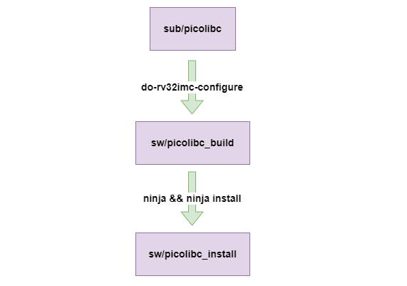
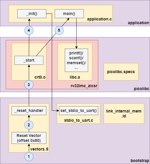
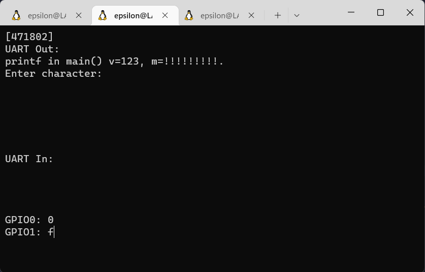
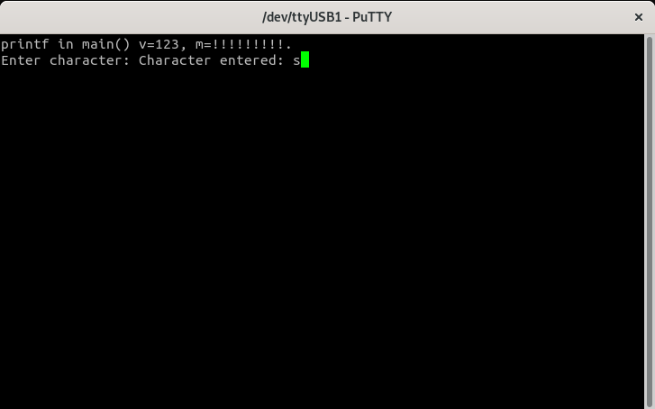
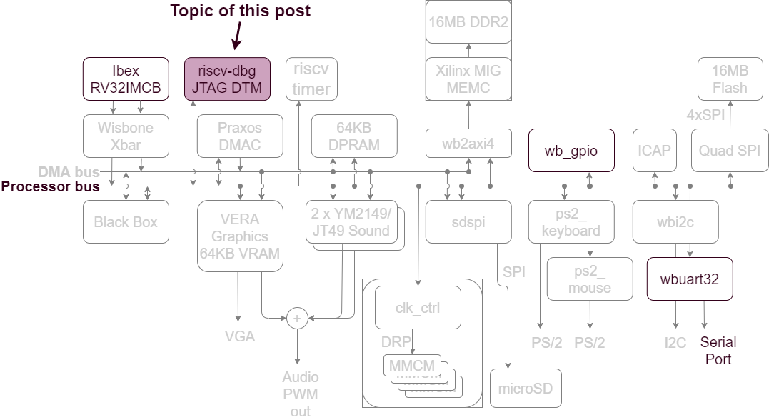
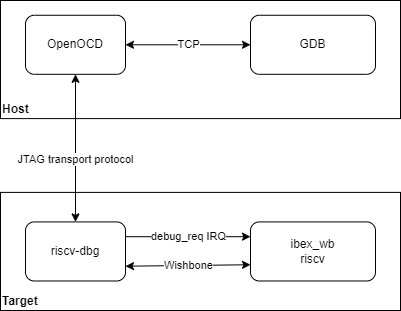
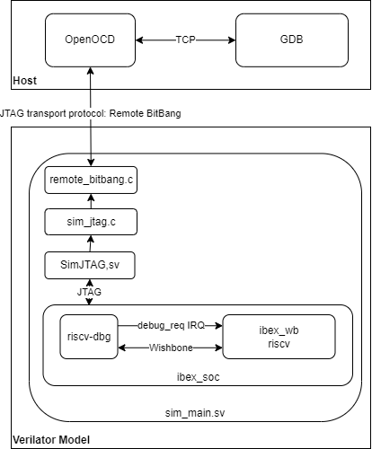
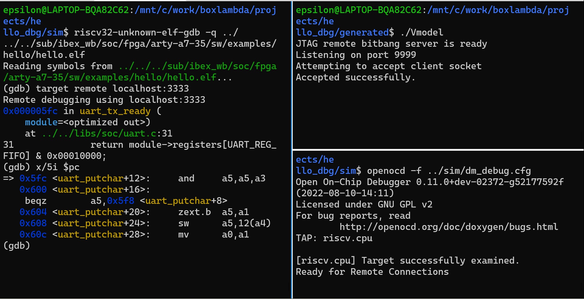 OpenOCD JTAG Debug Session on Verilator
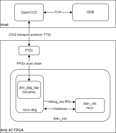
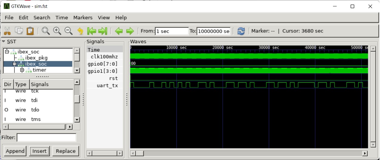 Gtkwave View of Waveform Trace Generated by *Hello World Verilator Test Bench*
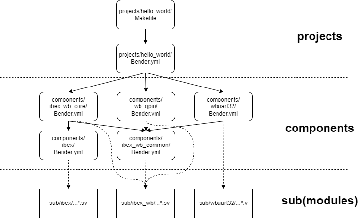
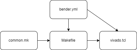
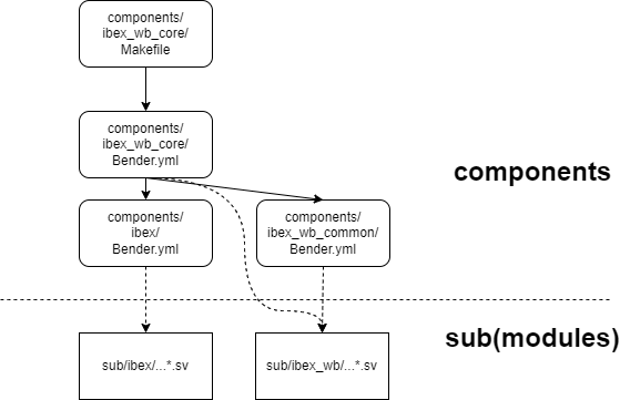
 Iterative Design Spiral
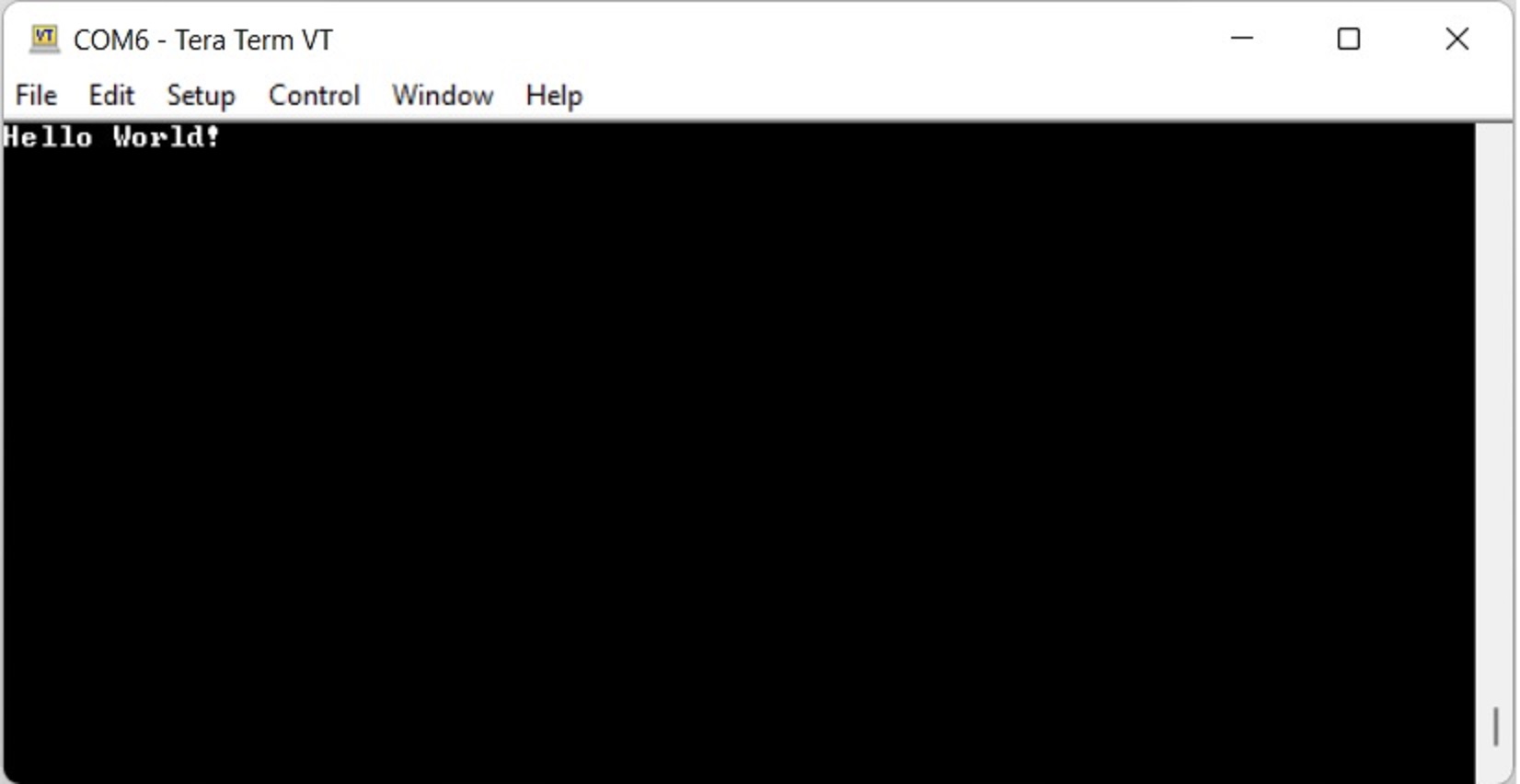 Hello World! from ibex_wb on Arty A7-35T
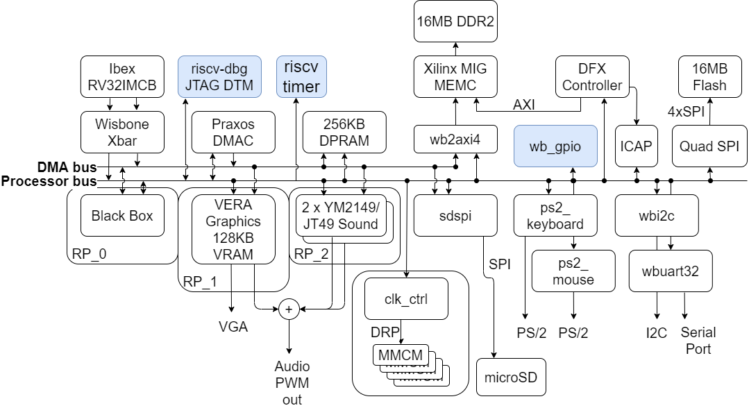 BoxLambda Architecture Block Diagram (Nexys version)
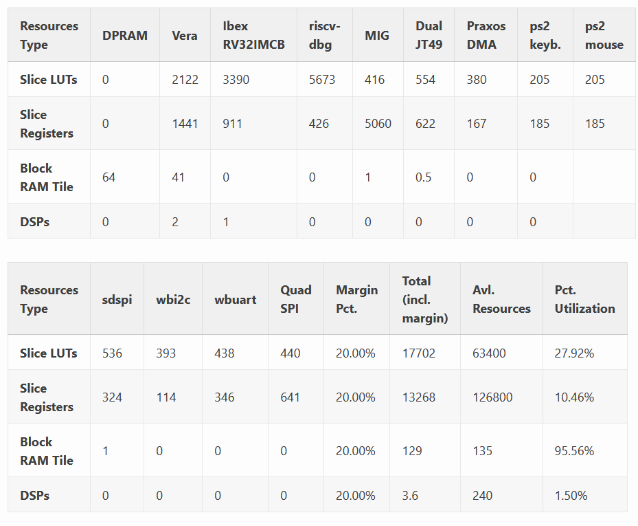
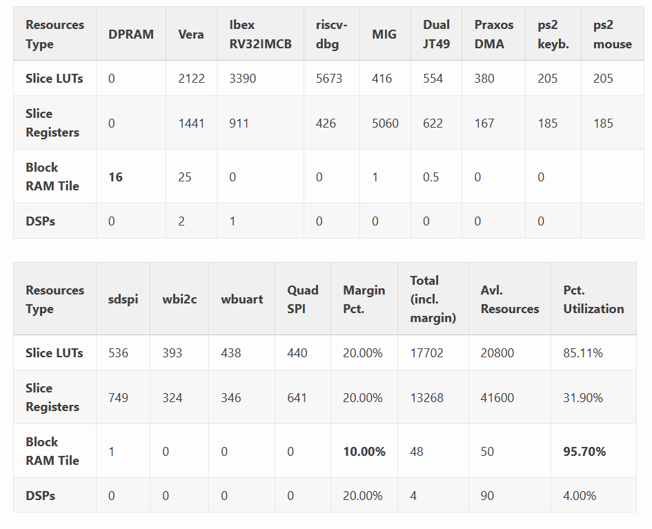
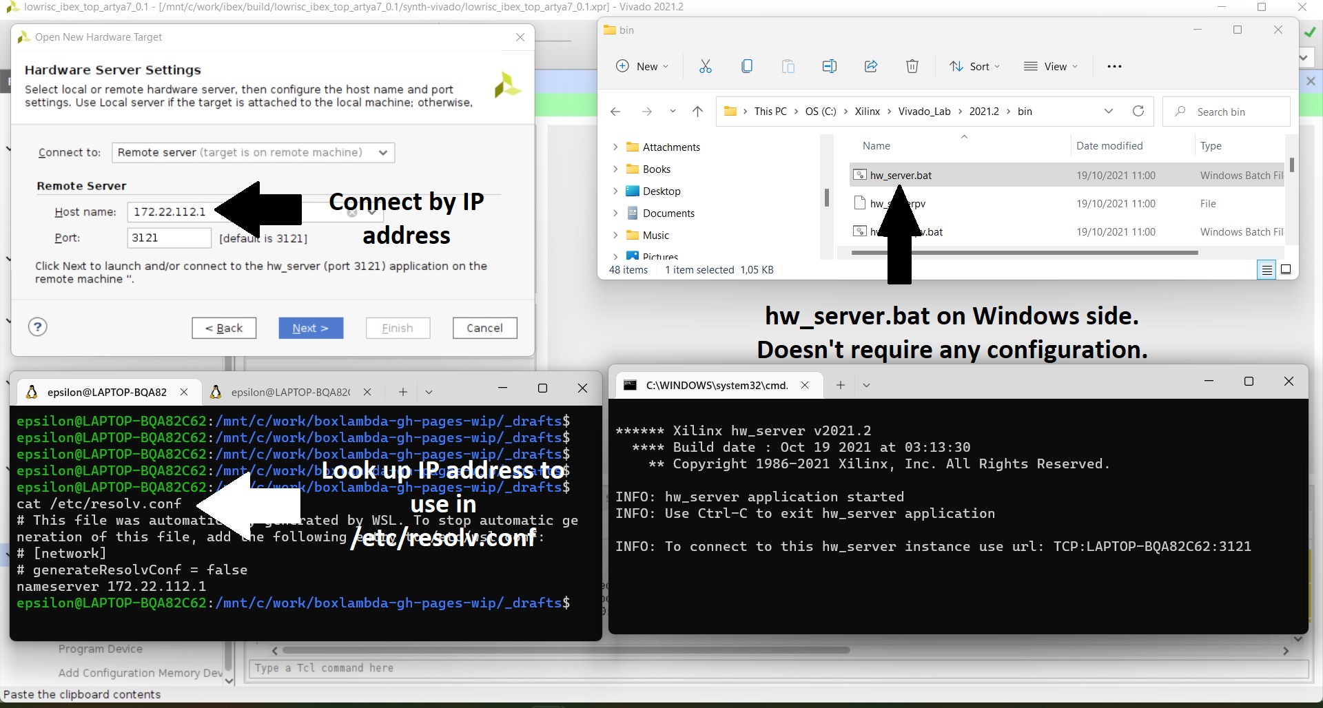 Connecting to Target from Vivado on WSL
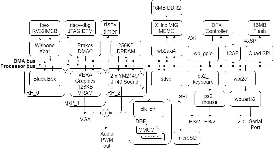

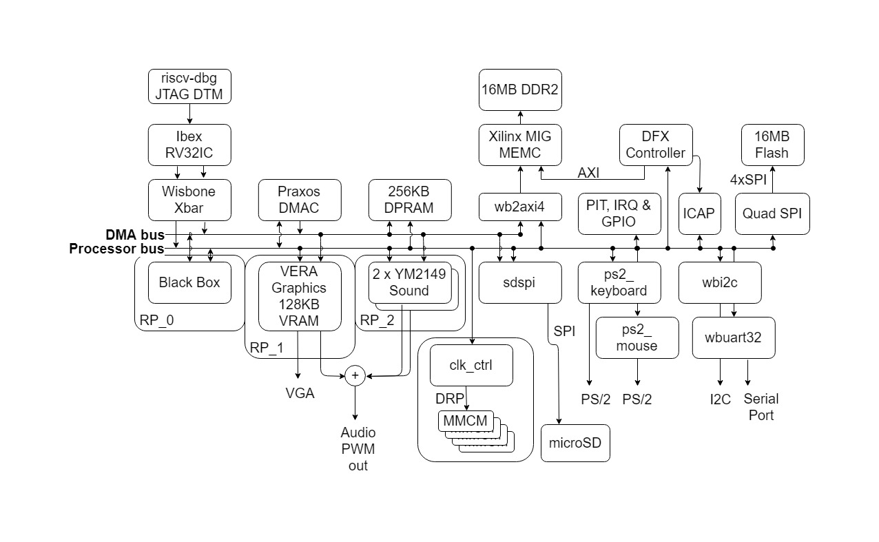 BoxLambda Draft Architecture Block Diagram for Nexys A7-100T.
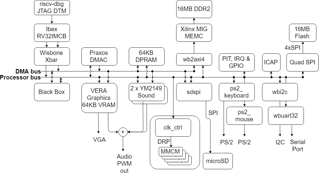 BoxLambda Draft Architecture Block Diagram for Arty A7-35T.