 NuclearPhoenix
Here are some of the most important key facts:
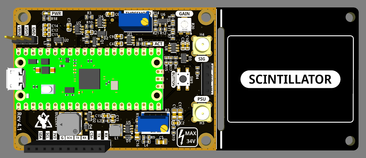
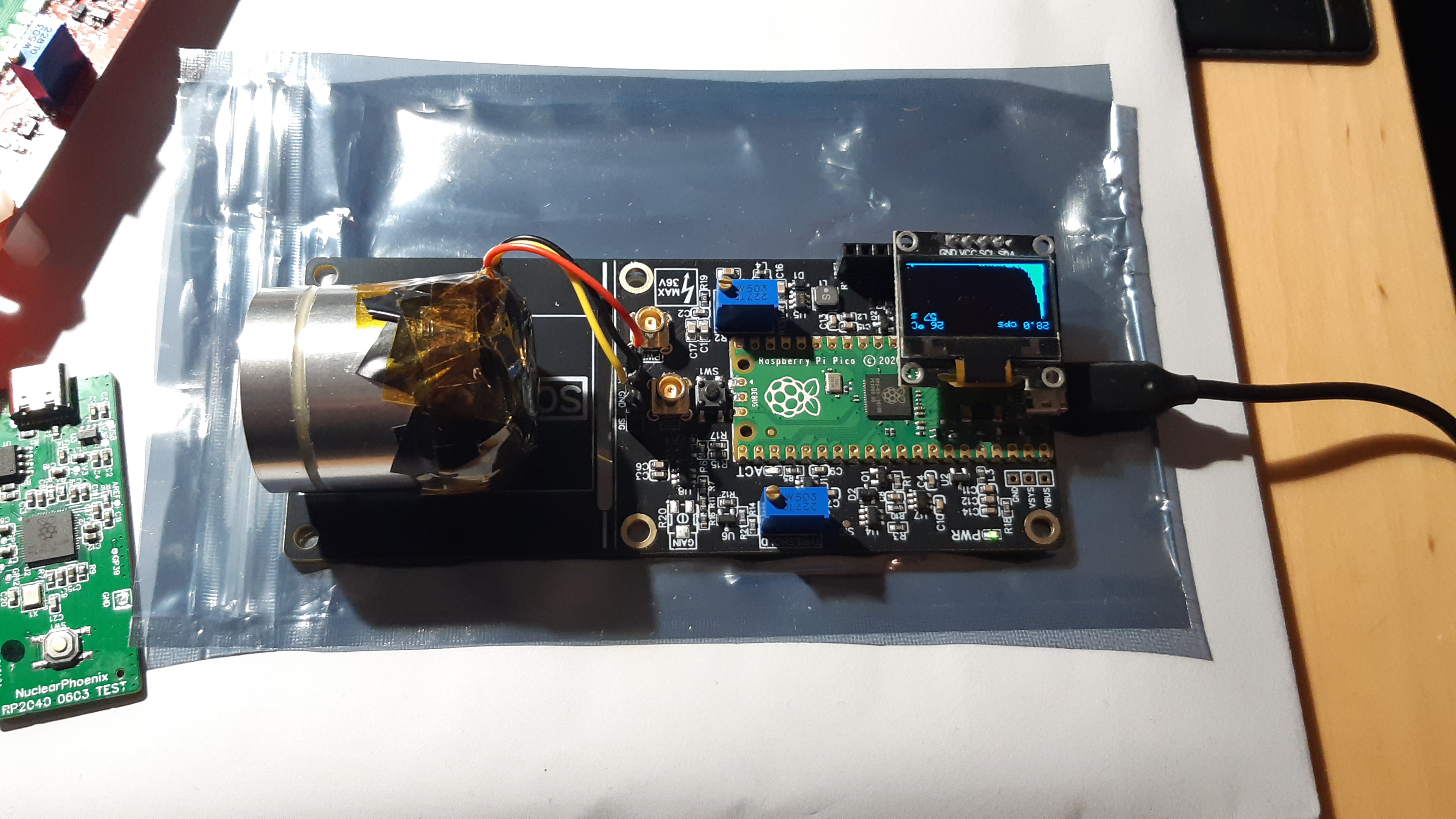
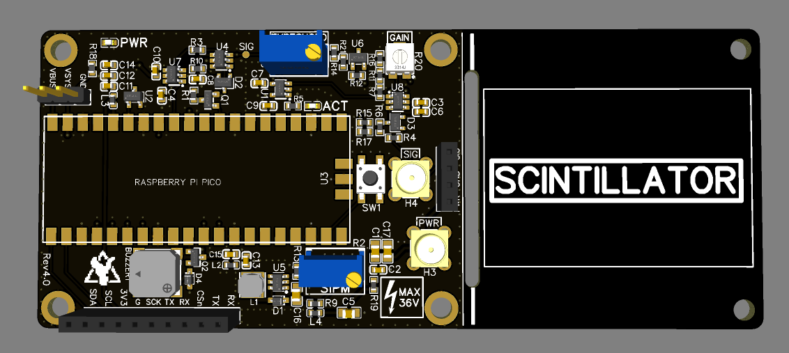
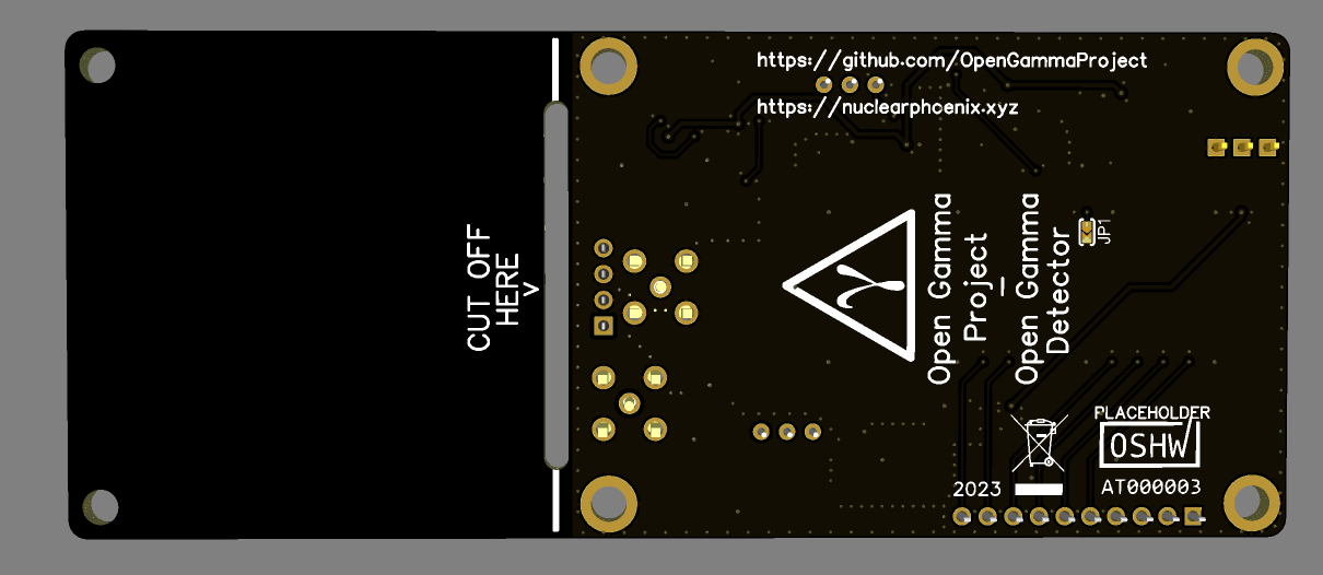
- Compact design: Total size 120 x 50 mm. Approx. 70 x 50 mm area for electronics and additional 50 x 50 mm to mount a scintillator.
- All-in-one: No external parts (e.g. sound card) required to record gamma spectra.
- Standalone spectra recordings on built-in flash.
- Easily programmable using drag-and-drop firmware files or the standard Arduino IDE.
- Low-voltage device: No HV needed like with photomultiplier tubes.
- Can use SiPMs in the voltage range of 27.5 V to 33.8 V.
- 4096 ADC channels with built-in 3 V voltage reference.
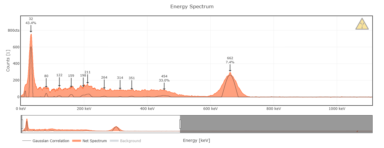
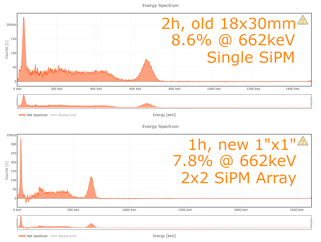
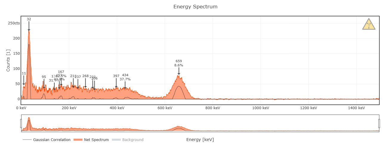
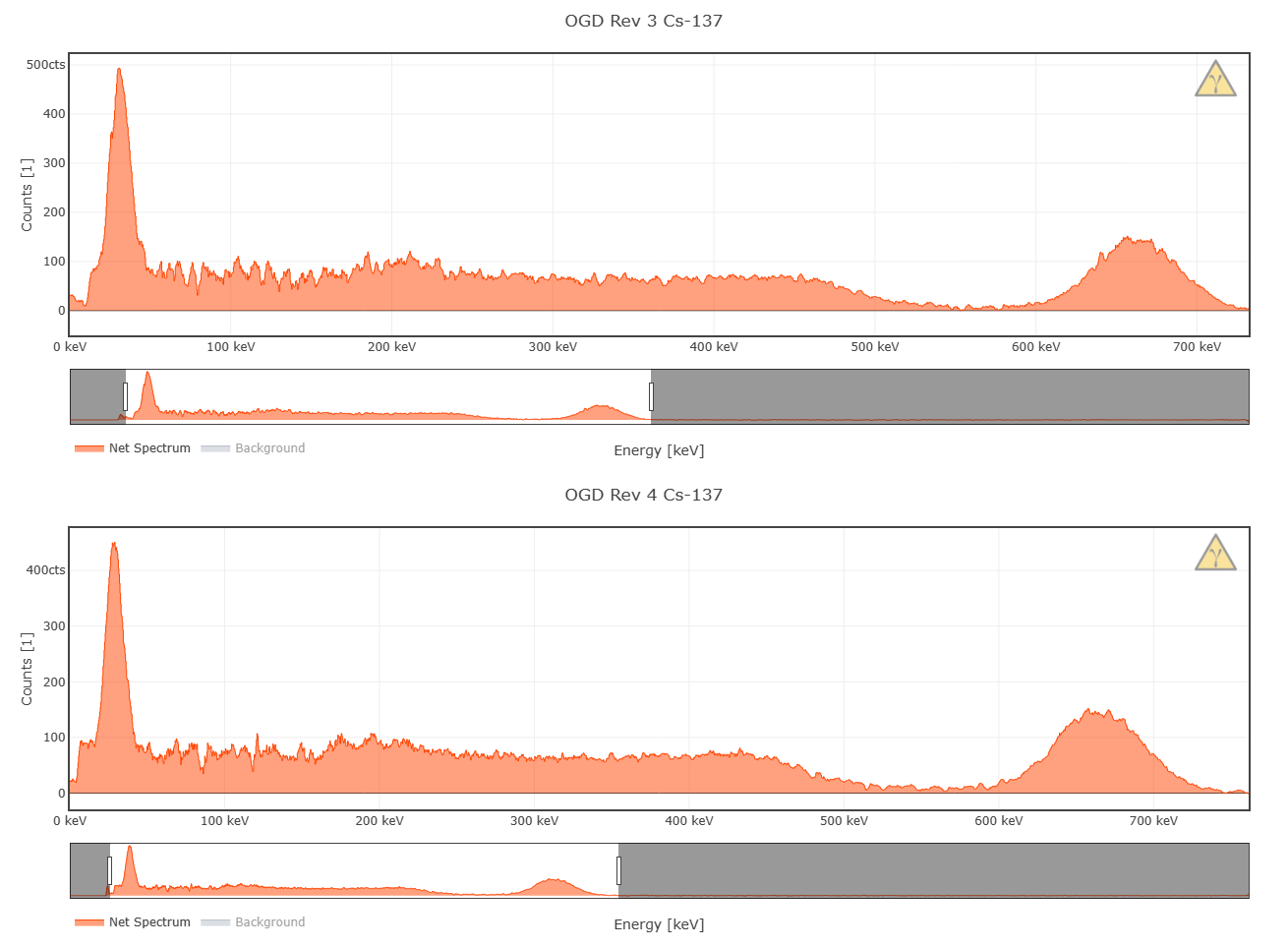
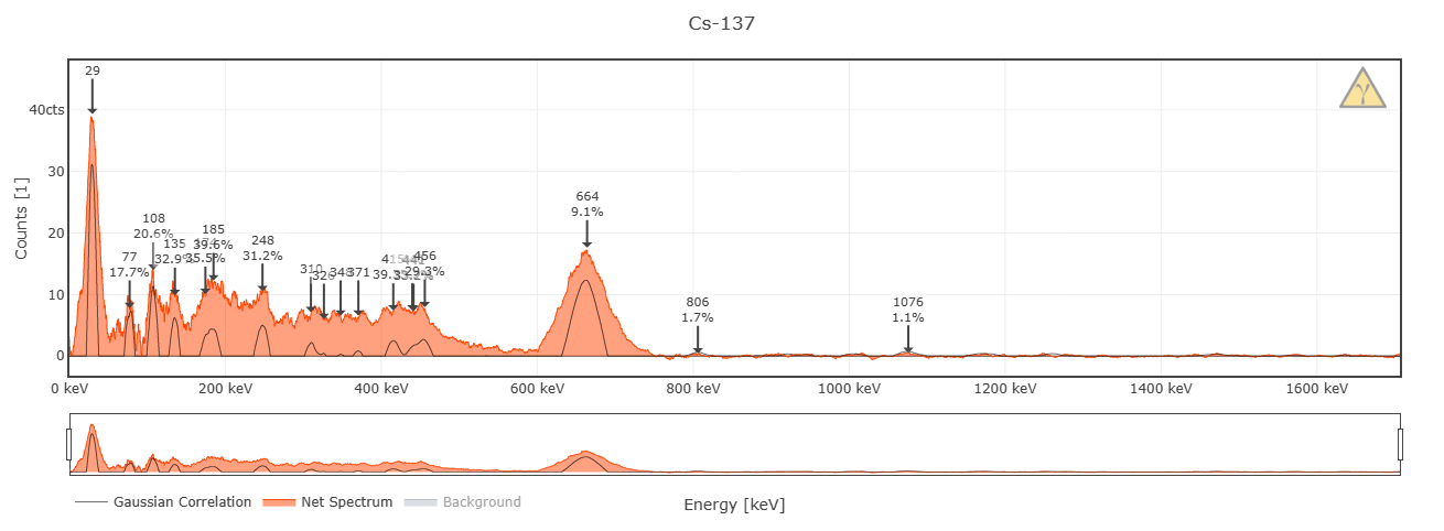
- Energy resolution of up to 7% @ 662 keV possible; highly dependent on your SiPM/scintillator assembly.
- Energy Mode: ~20 µs total dead time while measuring energy (default settings).
- Geiger Mode: <5 µs total dead time without energy measurements (default settings).
- Low power consumption: ~20 mA @ 5 V with default firmware at normal background.
- Built-in ticker (buzzer) for audible pulse count rate output.
- Additional broken-out power pins and I2C, SPI and UART headers for custom parts (e.g. display, µSD card, etc.).
- Simple OLED support out of the box (SSD1306 and SH110x).
- Built-in True Random Number Generator.
More information can also be found in the GitHub repository...
Ok nice, but how do I get it?
- DIY version: Download BOM and Gerber files or use Kitspace.
- Buy a complete board: Head over to Tindie.
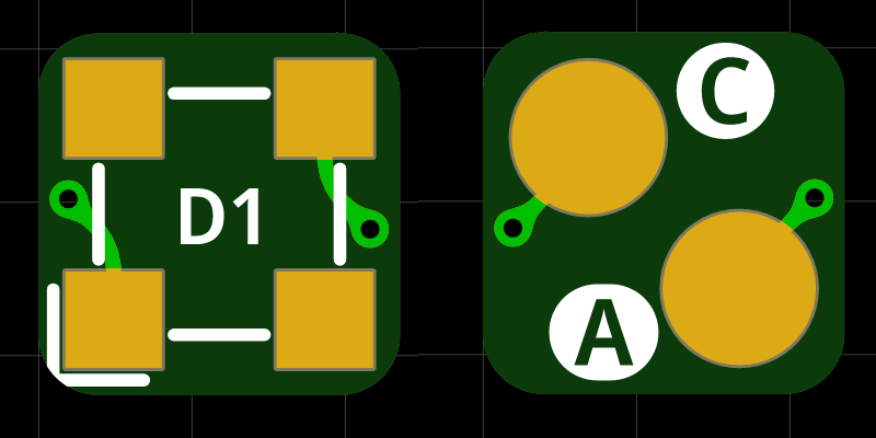
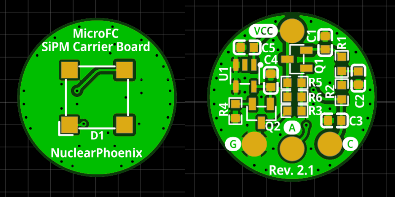
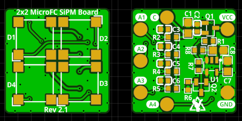
The principle of operation for the detector looks like this:
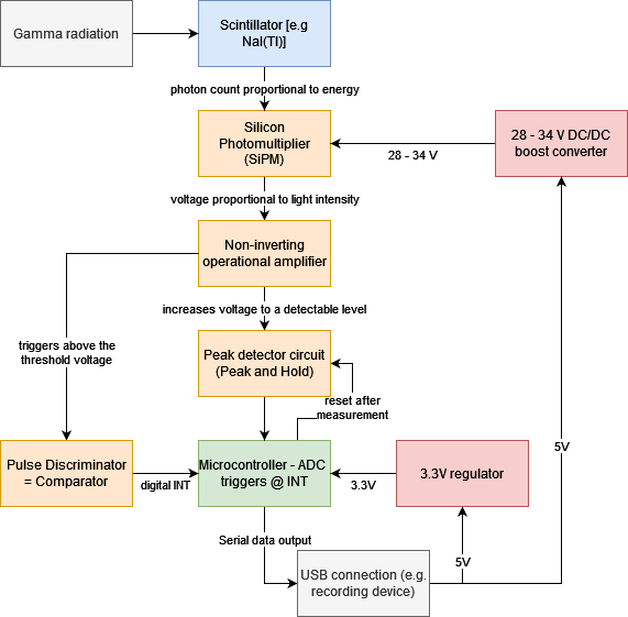
Read more »


 vysocan76
 Ondřej Petrlík
 The Big One
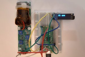
Hi,
I interested this project. I want to buy a complete board but it looks out of stock in Tindie. Is there anywhere else I can buy it? Will it be back in stock? Does anyone have knowledge about this?