 Ulrich
Lets make the short story long:
Often I got annoyed in my homeoffice and my workplace that i have to press over and over again same key combinations, change volume of my headset, enter phrases, mute my mic, mute my loudspeaker,.... You all know the typical tasks youz do you during a workday.
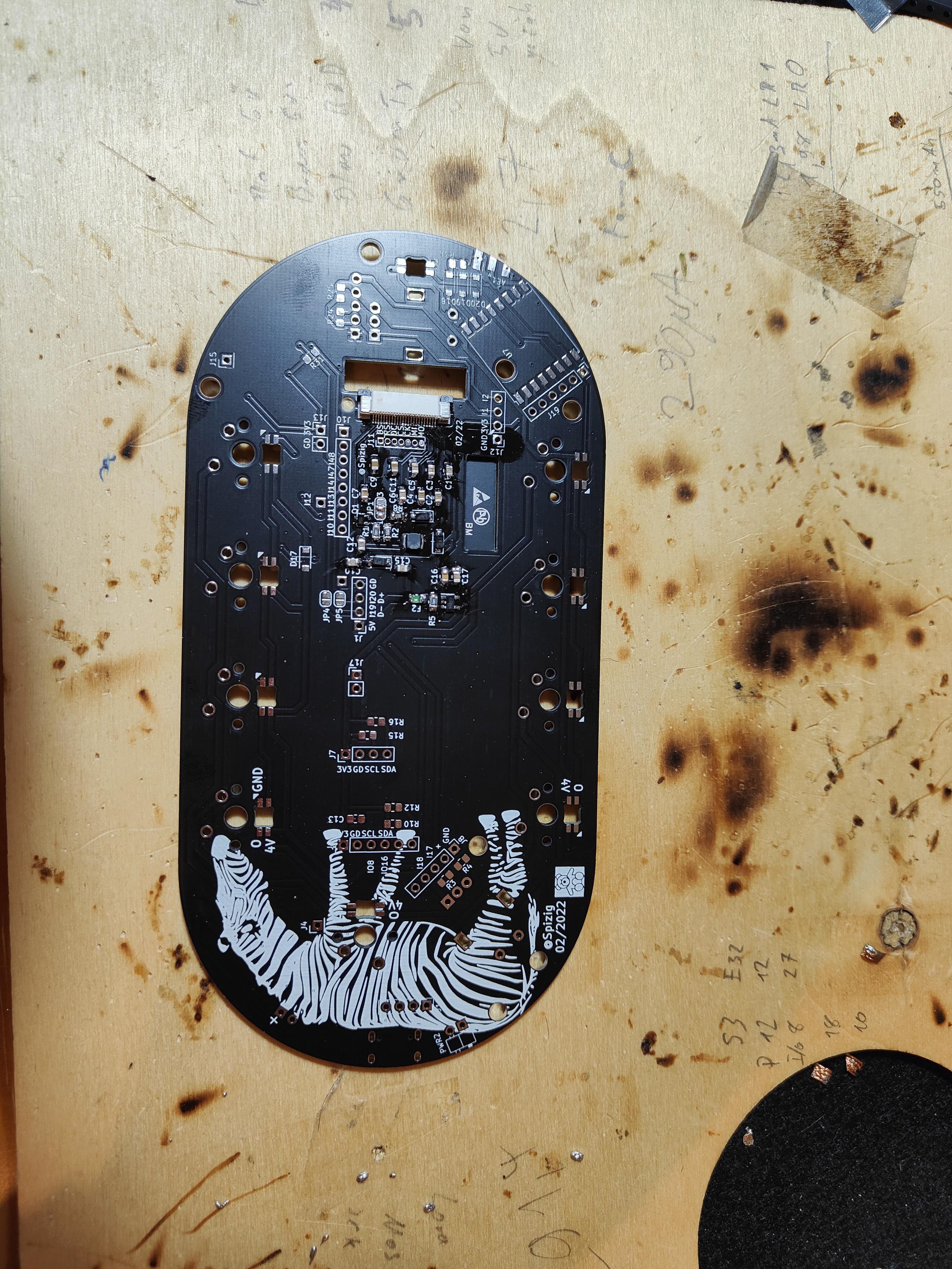
So there started this idea of an Shortcut Keyboard:
This Keyboard needed some more features than was available on the market... and I had the idea and the time in the winter to built it... and I am still building it.
Key facts in the Design Process:
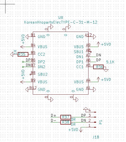
- Use it wired (secure communication), Charging of battery
- Use it Wireless (BLE) like a Keyboard,
- Use it Wireless with WiFi(for Remote Sessions),
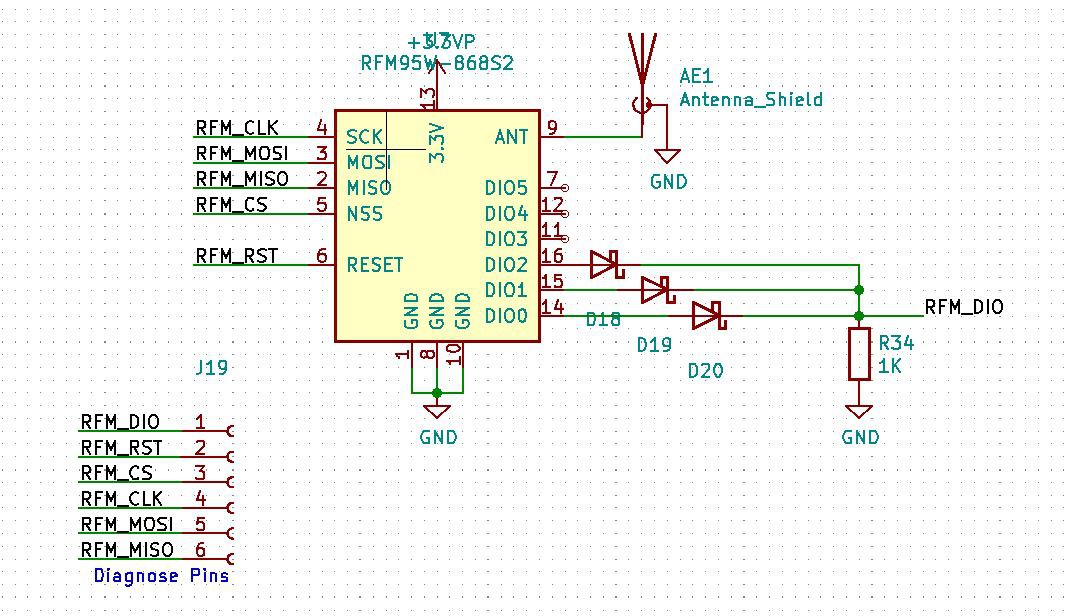
- Use it Wireless with LoRa (for very Remote Sessions out in the wild)
- Ultra LOW POWER. The whole thing shall automatically sleep if not used and save as much energy as possible(For Battery operation)
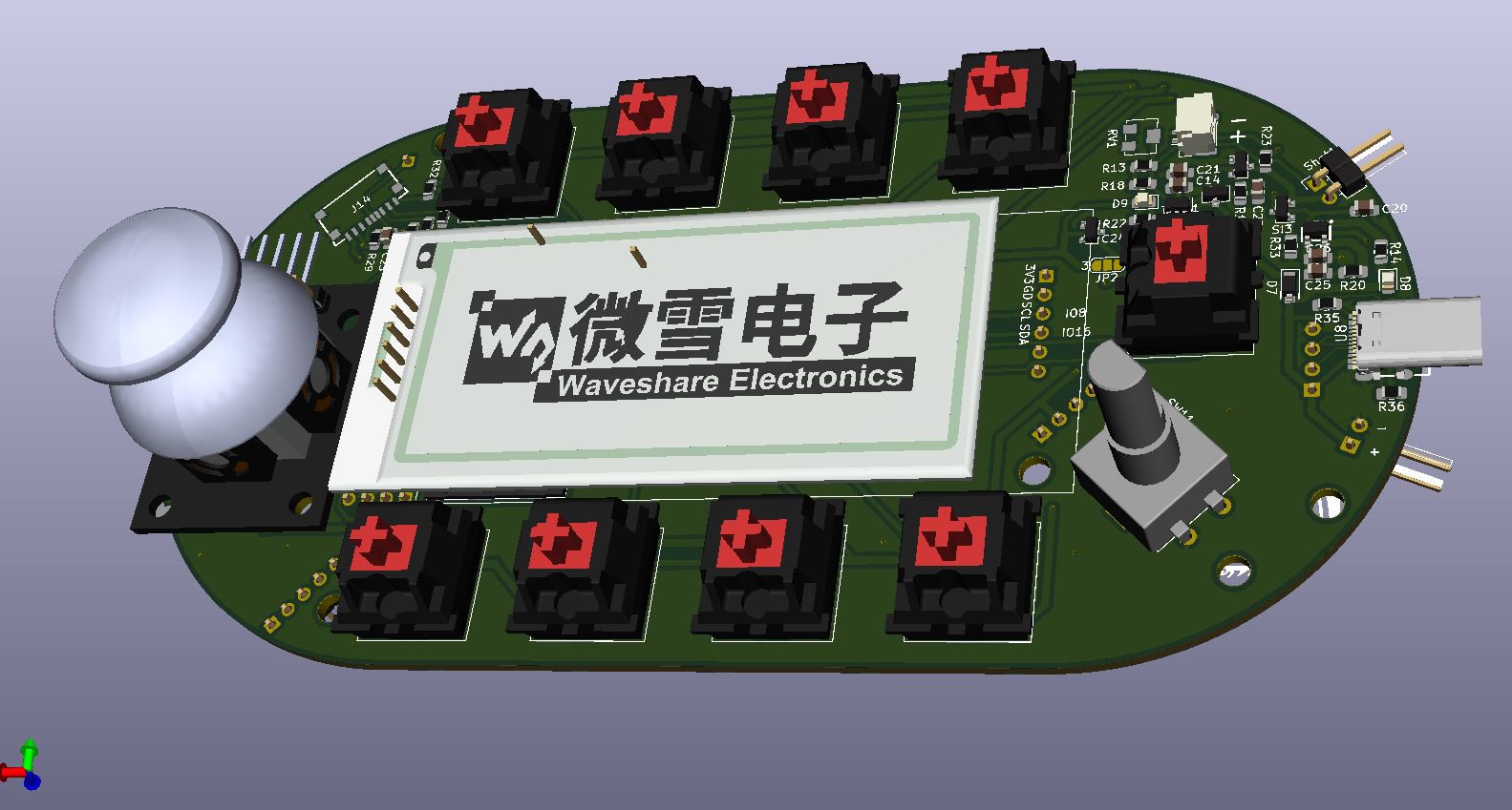
- Show some additional Data on a screen (Which Key does what, Room temperature,..)
- Volume Knob (including Mute)
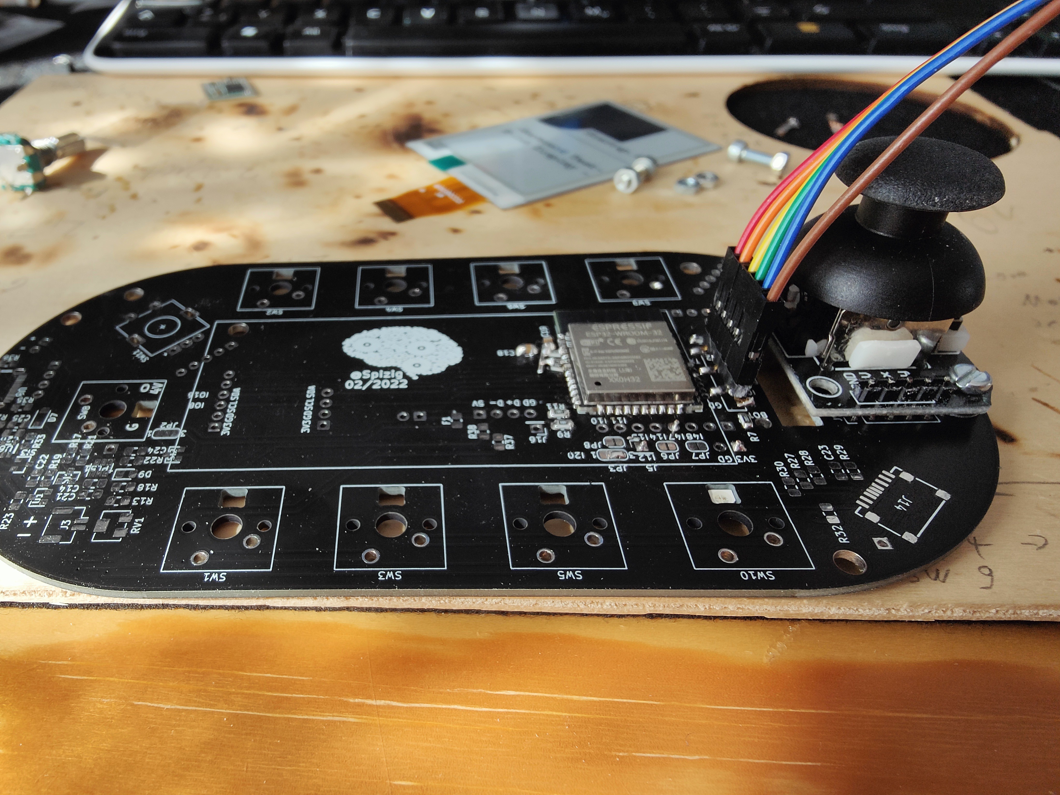
- Joystick or a Scroll Wheel (can not decide in design phase)
While Searching for something available on the market i did not found anything... but this one came close: Link ... A good design is always helpful. But this one was not doing all i needed.
So I decided to built this thing on my own.
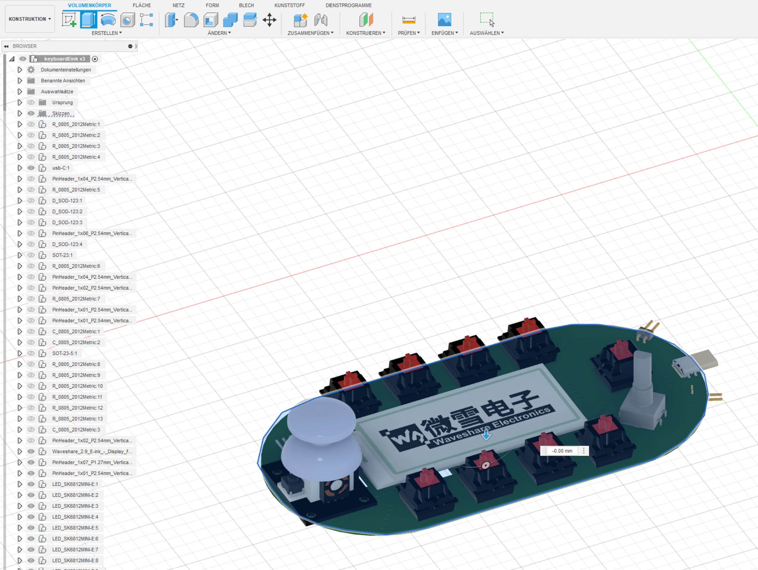
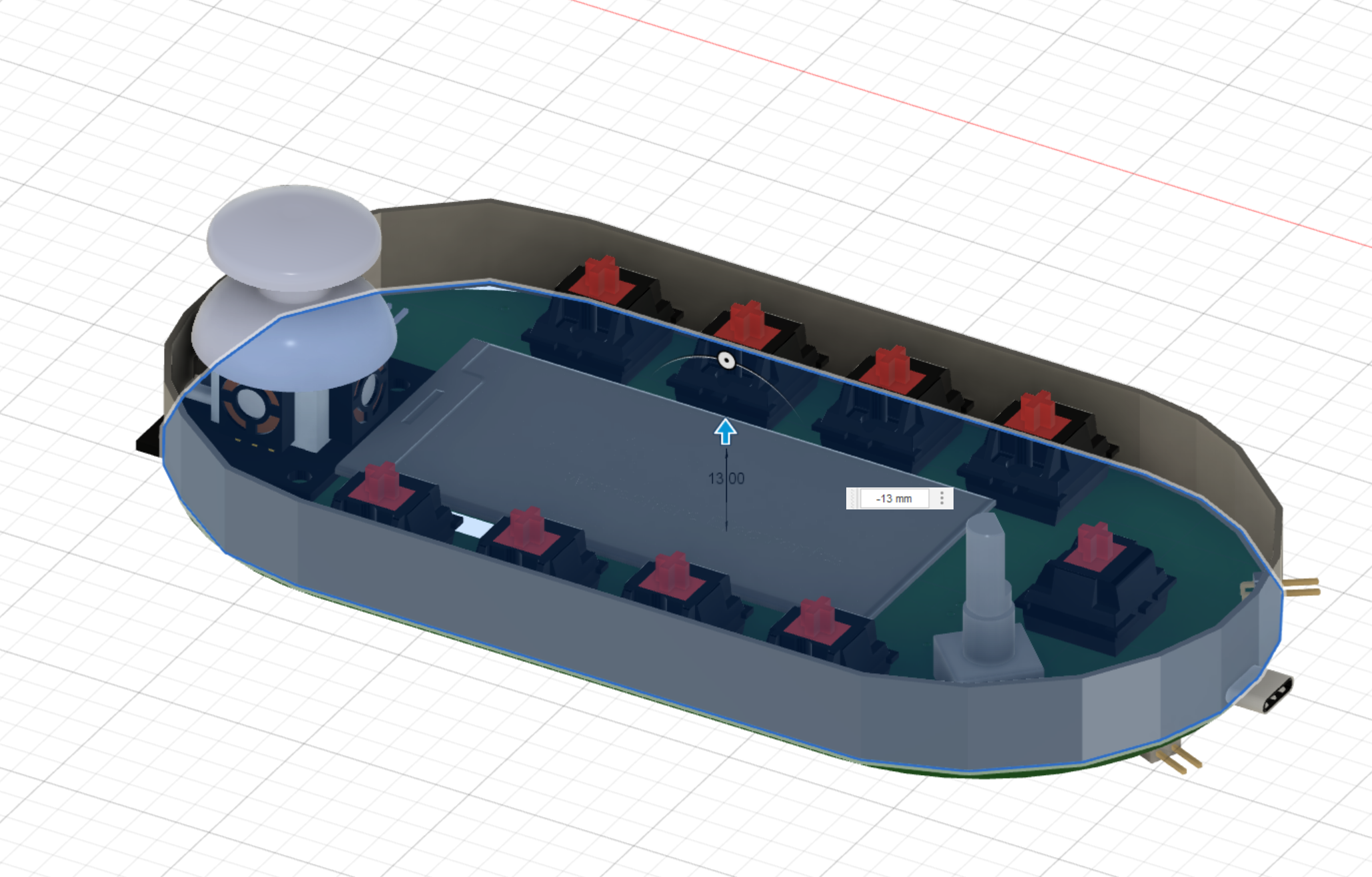
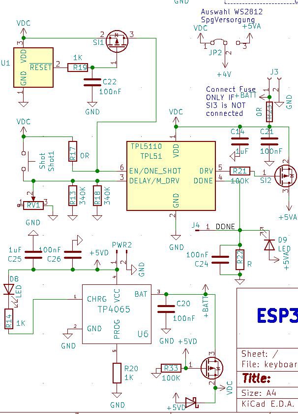
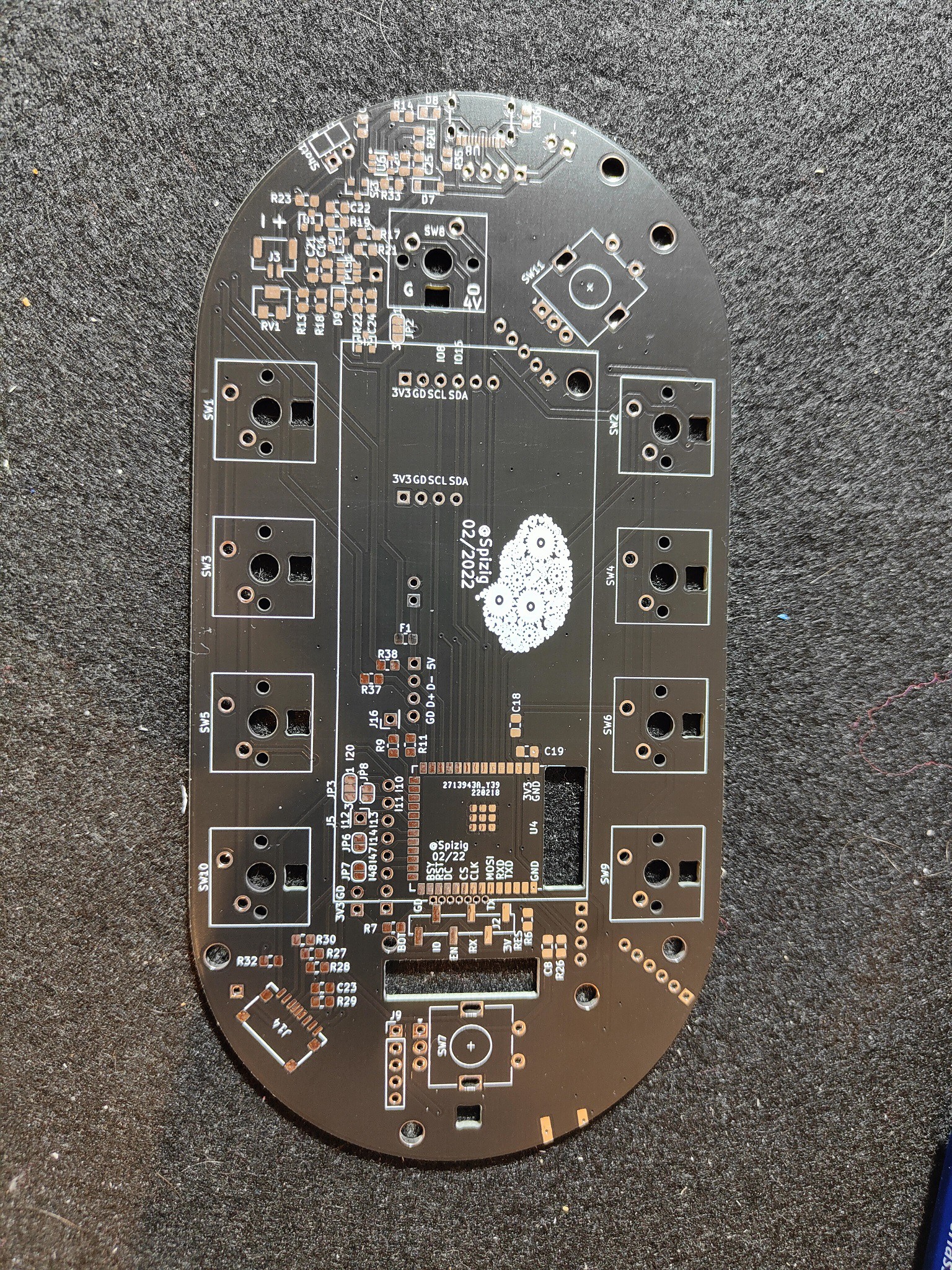
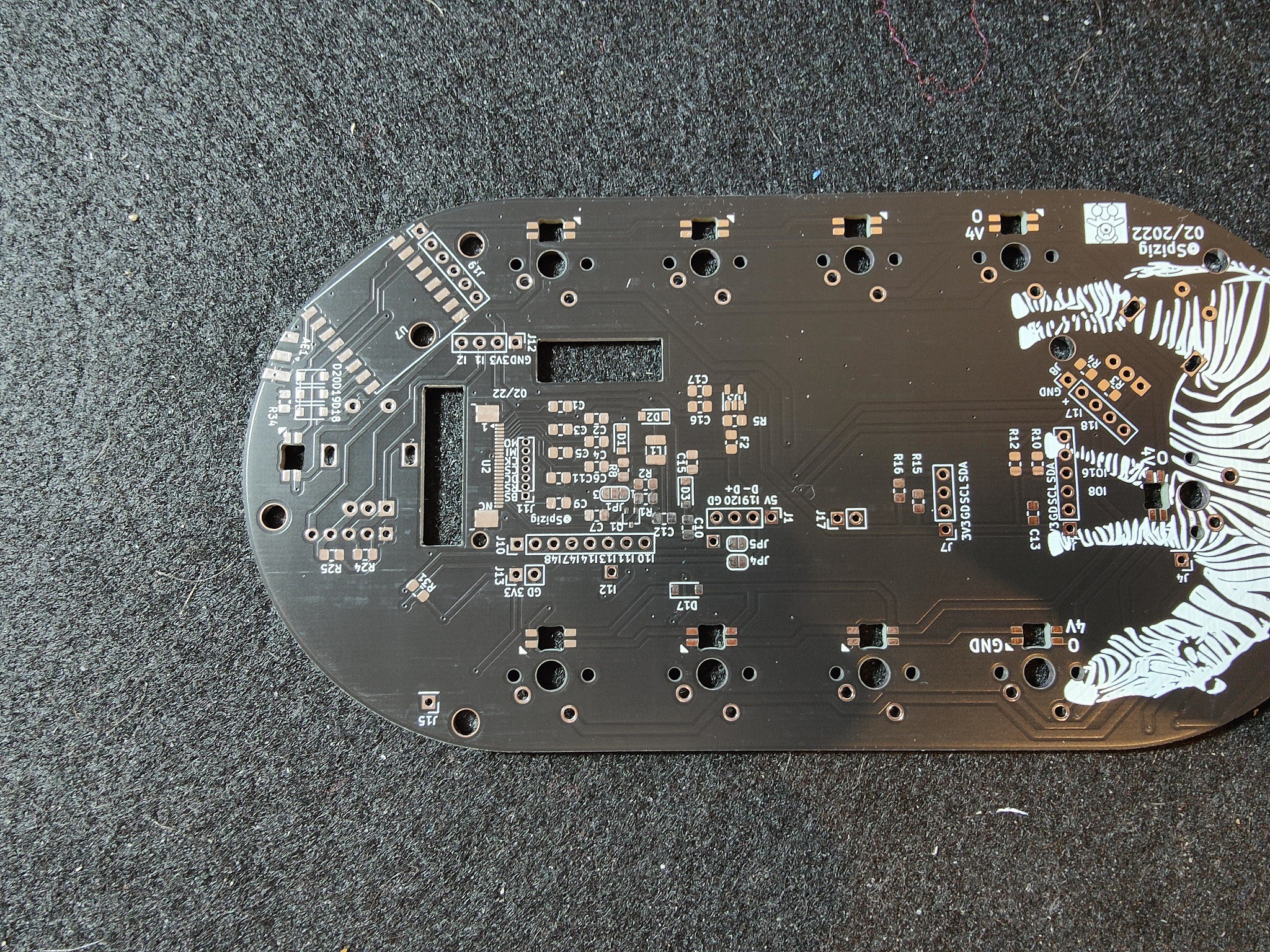
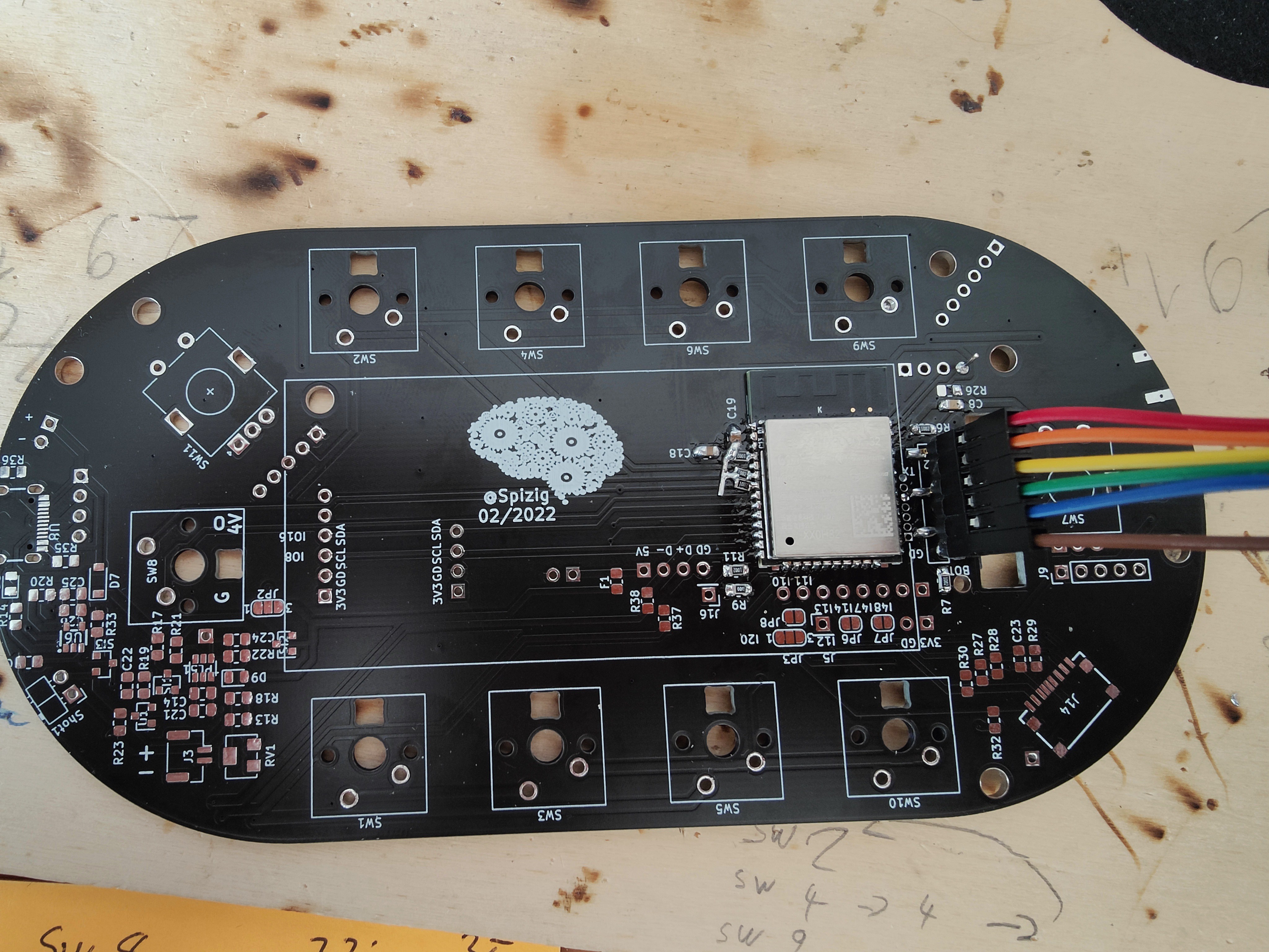
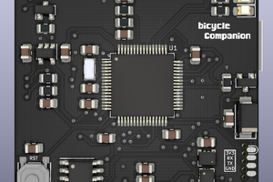
Lets start KiCad and make this thing happen.

 Matias N.
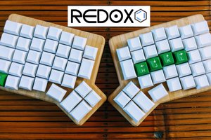
 Mattia Dal Ben
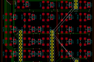
 Timm Murray
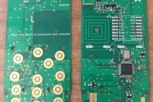
 Mastro Gippo