Hulk
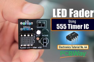
HulkThe 555 timer IC is an integrated circuit that is used in a variety of timer circuits, pulse generators and oscillator applications. The heart of the tutorial is the 555 timer IC that is wired as an astable multivibrator.
In this tutorial, I'll first blink "an LED" using the positive pulse generated by a "DIY 555 Pulse Generator Module" (video: https://youtu.be/bMAnipPOjFo), followed by "two LEDs" alternating and flashing at a regular interval. The output frequency of pulses can be adjusted using a potentiometer. The circuit can be operated from any voltage between 5 to 15 volt DC.

Watch this video for detailed step by step instructions on how to build this circuit and for a complete instruction on how the circuit works.
Items Required

For this tutorial we need:
2 x LEDs
1 x 555 Timer IC
1 x 10µF Capacitor
1 x 220Ω Resistor
1 x 1kΩ Resistor
1 x 10kΩ Resistor and/or
1 x 10kΩ Potentiometer
Circuit Diagram
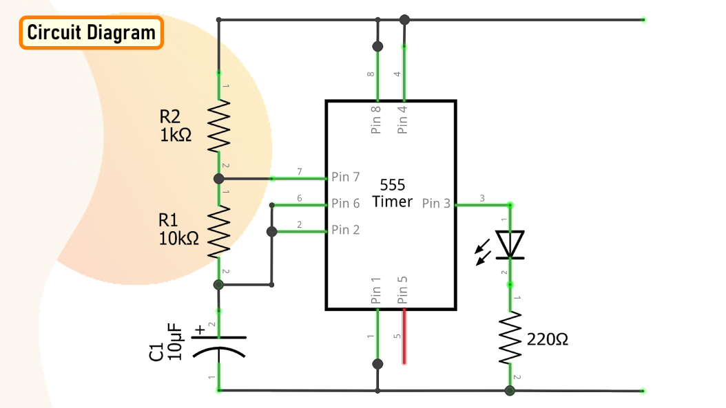
The circuit is very simple.
By connecting Pin 2 and 6 of the 555 timer IC, we put the IC in astable mode. In astable mode, the 555 timer IC acts as an oscillator (re-triggering itself) generating square waves [PWM Signals] from the output pin no. 3.
By changing the values of R1, R2, and C1 we can change the frequency of the output pulses generated at pin number 3.
Alright, let me explain this with the help of an animation.
How The Circuit Works
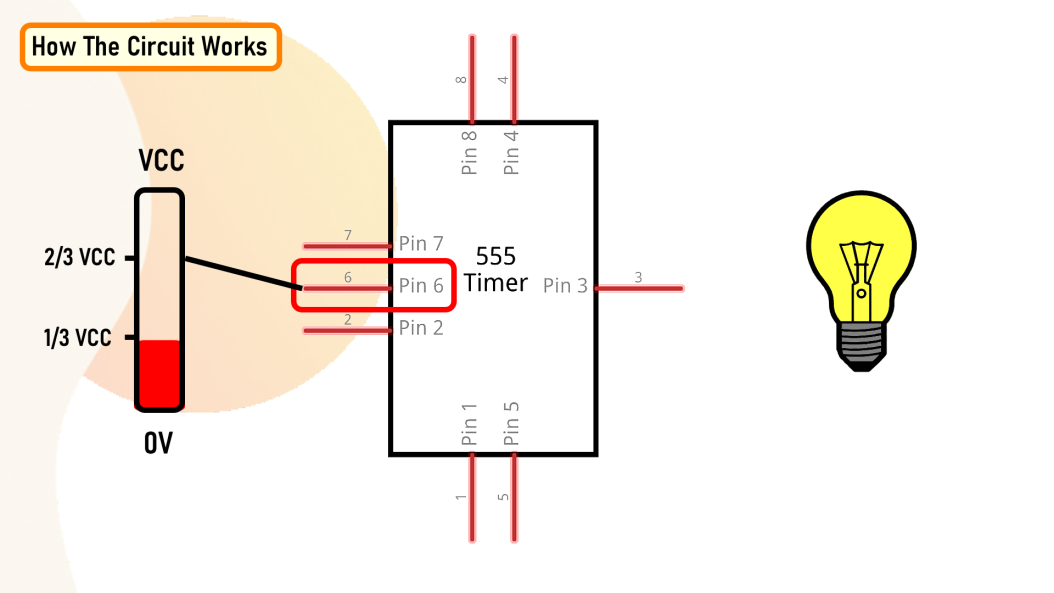
* When Pin 2 of the IC detects voltage LESS than 1/3rd of the supply voltage, it turns ON the output.
* And, when Pin 6 detects voltage MORE than 2/3rds of the supply voltage, it turns OFF the output.
* When the output is OFF, the Discharge Pin (Pin7) gets internally Grounded.
This is how the trigger pin (Pin2) and the threshold pin (Pin6) of the 555 timer IC sense voltages and controls the output at Pin 3.

* Capacitor C1 will be in a discharged state immediately when we firing up the circuit.
* So, the voltage at Pin 2 will be 0v which is less than 1/3rds of the supply voltage, this will turn ON the output on Pin 3.
* At the same time Pin 7 will internally disconnect from the GND and the Capacitor C1 will start changing via resistors R1 and R2.
* Once the voltage across capacitor C1 crosses 2/3rds of the supply voltage, Pin 6 turns OFF the output.
* At the same time Pin 7 will internally reconnect to the GND causing the capacitor C1 to discharge via resistor R1.

* Once the voltage across the capacitor C1 falls below 1/3rd of the supply voltage, Pin 2 turns ON the output, and the above cycle keeps repeating itself.
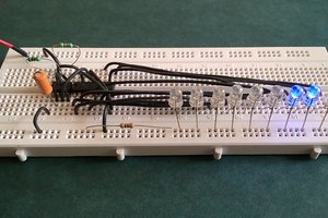
You can hook up a multimeter to the circuit to measure the charging and discharging of the capacitor.
Since resistance R1 is involved in both charging and discharging of the Capacitor, increasing or decreasing its value will increase or decrease the duration of the OFF cycle and will decrease or increase the flashing rate of the LED, as the capacitor will take more time to charge and discharge.
By replacing the capacitor with a higher or lower value, you can also get a longer or shorter flashing rate.
By replacing the resistor R1 with a potentiometer the blinking rate of the LED can be dynamically adjusted.

Now, for the Dual LED flashing effect we need to connect a second LED with opposite polarity to the Pin 3 of the IC. That's it, as easy as that.
Calculations

Now, lets calculate the output frequency and the duty cycle of the output waveform.
In my setup I have resistance R1 = 1kΩ, R2 = 10kΩ and capacitor C = 10uF
There are many online calculators to calculate this online. I will provide a link to one of the astable calculators in the description below: https://ohmslawcalculator.com/555-astable-calculator
Lets first calculate the value of t1 or the 'capacitor charge “ON” time which is 0.693(R1 + R2 ) * C1. Putting the values together we get 76.23 milliseconds.
Now, for capacitor discharge “OFF” time or t2 we need to multiply 0.693 to R2 and C1, which then gives us a value...
 kamalkedin123
 matseng