ElectroBoy
Thinking a little bit on audio recording device, Mic section attracted my attention. In mobiles inbuilt amplifier is enough to record the sound via external microphone. That’s why no preamplifier required. But while recording with camera device this mic system is not provide enough gain and hence voice get distorted. So, we always use a microphone which has camera option. This usually increase the signal gain.
This article is brought to you by JLCPCB, you can get 5pcs of 2layer PCB in just $2 and PCB assembly service in just $8. Visit JLCPCB to know more about offers and services. Get free coupons of $54 on first sign-up to JLCPCB.
Condenser microphone working:

A condenser microphone is an active transducer that converts sound waves (mechanical wave energy) into audio signals (electrical energy) via the movement of a diaphragm in a fixed-charge capacitor-based capsule and electrostatic principles. A very little amount of signal in the range of few millivolts is generated. It is not useable under any condition for recording.
Mic amplifiers:
There are many small amplifier available nowadays in market which can amplify the sound signal to a hundreds of millivolts and even higher. Most of them use operational amplifier non inverting configuration to amplify the sound. And due to this you can also found dedicated mic amplifier integrated circuits on internet.
Components required:
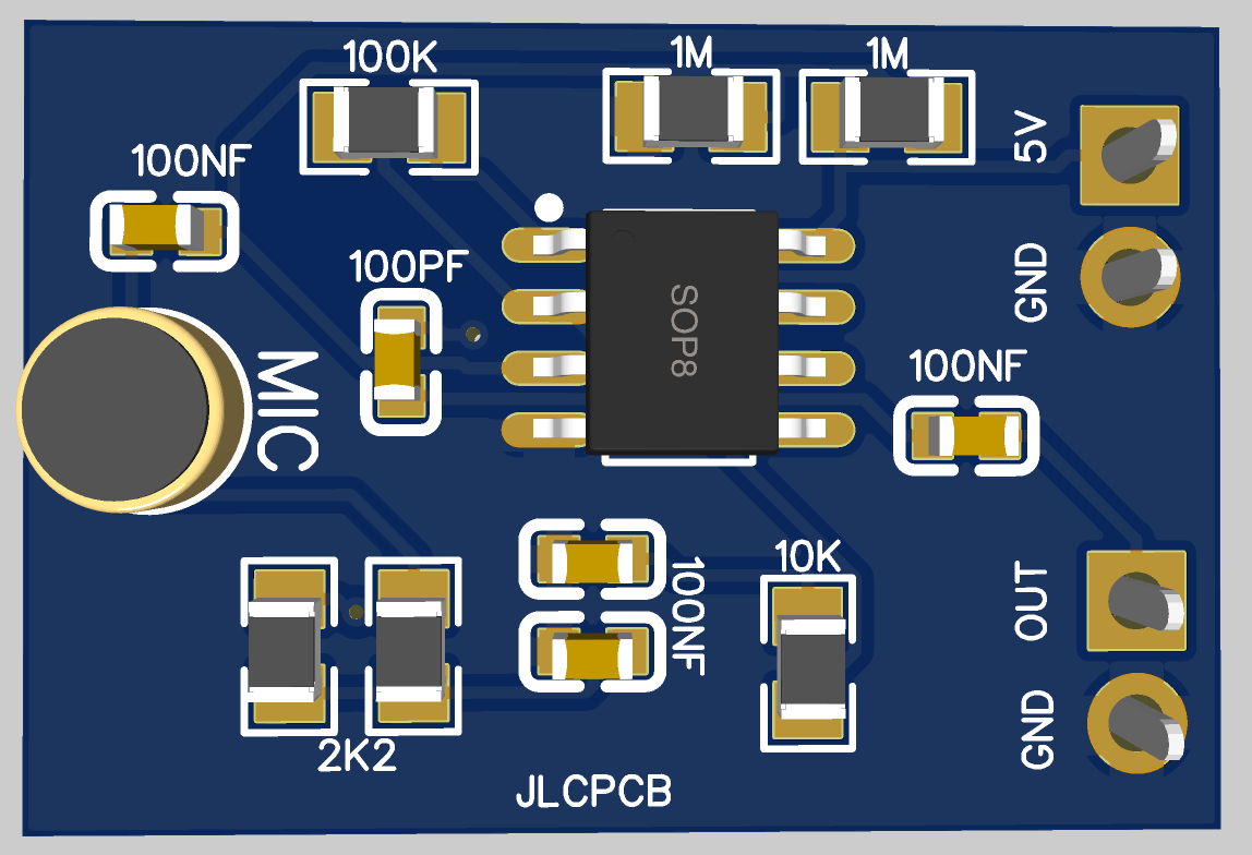
1) JRC4558D operational amplifier
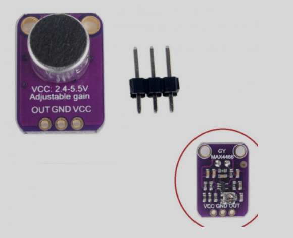
2) Condenser microphone
3) 1M, 100K, 10K and 2k2 resistor
4) 1nf and 1uf ceramic capacitors
5) 5-volt power supply
6) Custom PCB files
PCB files:
After modifying the circuit, I made a schematics and then turned it not a PCB. IF you want to use the same designs as mine then get them from here. I always use JLCPCB for my pcb prototype projects. Because they are providing the best service in very low price.
You can get 5pcs of 2layer PCB in just $2 and PCB assembly service in just $8. Visit JLCPCB to know more about offers and services. Get free coupons of $54 on first sign-up to JLCPCB.
Circuit diagram:
Here in the circuit operational amplifier is used in single supply mode. Because microphone is a battery operating device, dual power supply can’t be mounted on PCB. We used resistor divider network to set the middle voltage at VCC/2. Ceramic capacitors of 100nf are there to reduce the overall system noise.

I used 4558d operational amplifier, but any other op amp with same configuration will work as charm. R7 and R8 resistor to adjust the gain of the operational amplifier. If you want the adjustable gain then place a 47k potentiometer instead of 10k resistor. This is the non-inverting configuration and the gain of our circuit can be given as:
1+R8/R7 = 1+100/10= 11
Vout= Vin(gain) that is Vout= Vin(11)
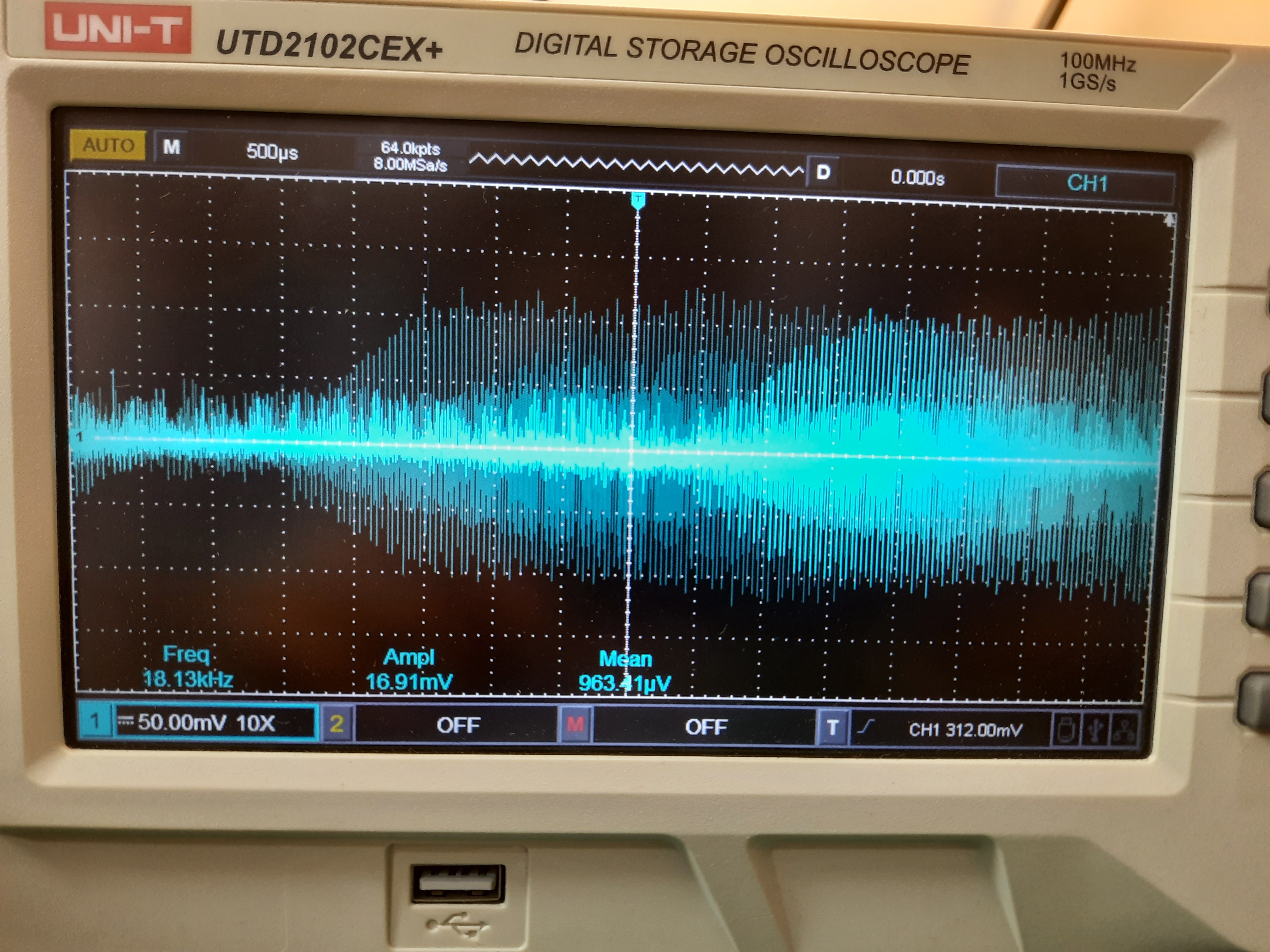
So the input signal is amplified 11 times, if the input signal is of 10 milli-volts then an output of 110 milli-volts is generated.
You can get more gain by increasing the ratio of R8/R7, but keep in mind noise will also amplified with the gain. Try to use low noise operational amplifiers. Try SMT assembly service of JLCPCB all the required files are provided her in the description.
 Sagar 001
 ElectronicABC