 alberto nunez
Repurposing a PLC clone for use with Arduino
It is fairly common to find in online shopping pages, advertising like this: “Industrial control board compatible with FX1N, FX2N, FX3U and programmable with GX software”. The price is attractive, however, the documentation is non-existent, and there is no mention of how to program it with other tools like Arduino in other operating systems different from Windows. This article will introduce a few key concepts to help solve this problem.
Industrial control board compatible with PLC programming software of a specific manufacturer
Key component: Industrial control board compatible with FX1N
Attack of the clones
These boards mention compatibility with GX software, which is manufactured by a Japanese company that makes PLC and also cars. At first sight, the compatibility is not official, as no trademark is printed. Their origin is unknown, maybe they were simplified copies based on original schematics and source code, or somehow the native binary format of the PLC was reverse engineered and an interpreter was built and runs in the microcontroller translating the code. Most of the cards are based on STM32 microcontrollers, and according to some articles and videos, the original programming software actually recognizes them as an original PLC!
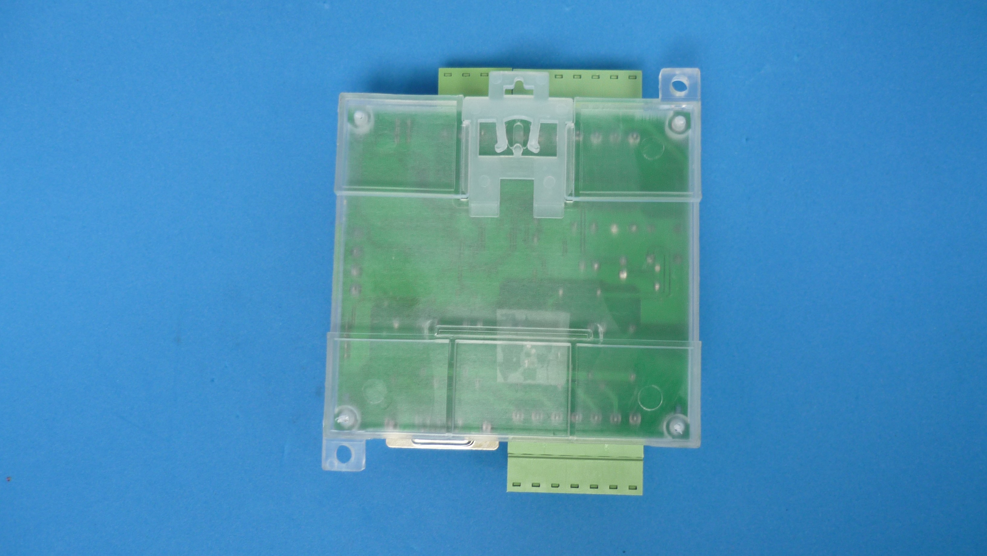
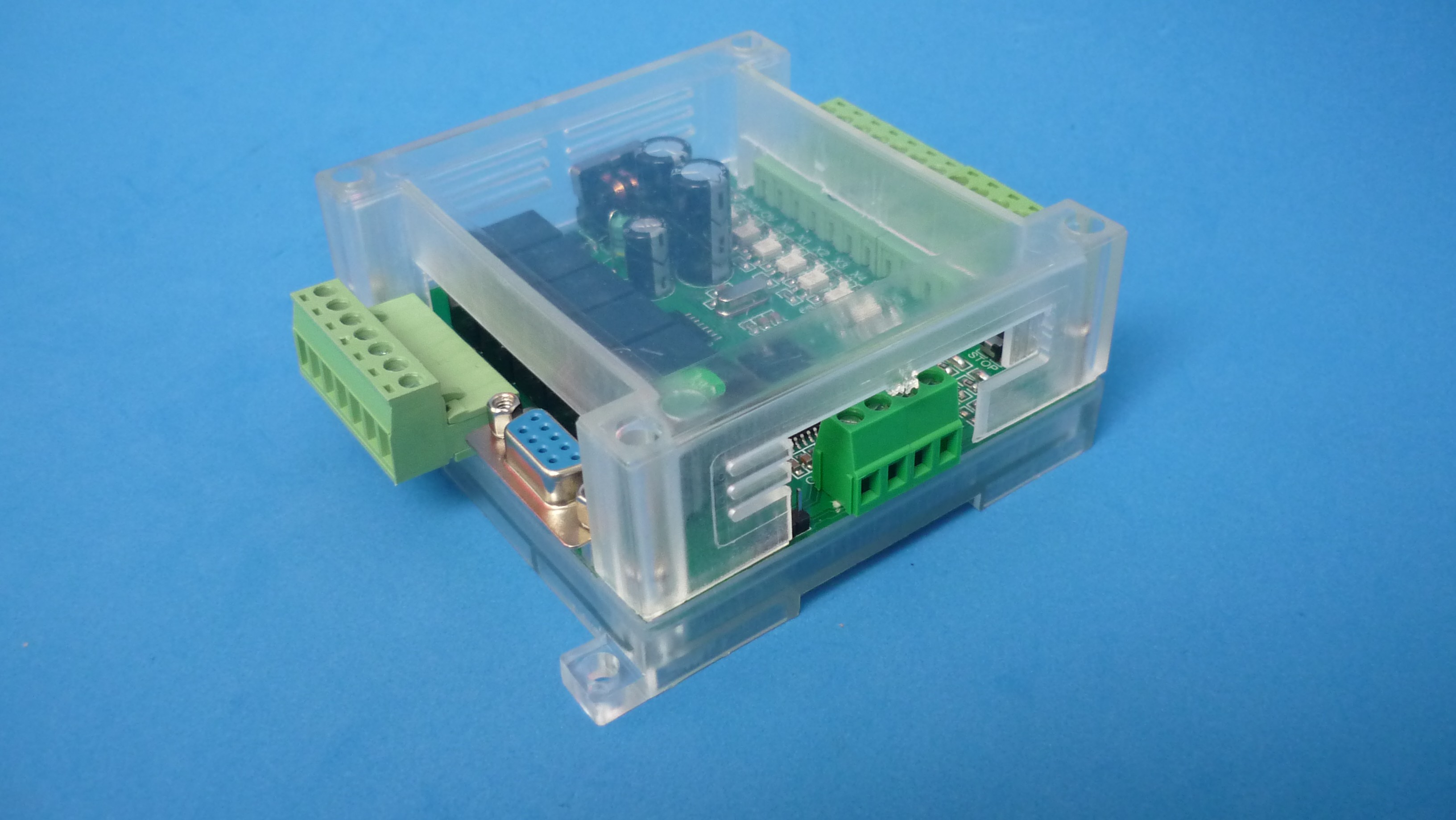
Plastic enclosure, DIN rail installation
Due to their low cost (around $25 USD), and for their relay isolated outputs, optically isolated inputs, RS232 serial port and regulated power supply, are great candidates for small projects as long as they can be programmed with a free multi-platform tool like Arduino or STM suite. In addition, a schematic diagram is needed to find out which I/O of the microcontroller goes to which peripheral in the board!
Bill of materials
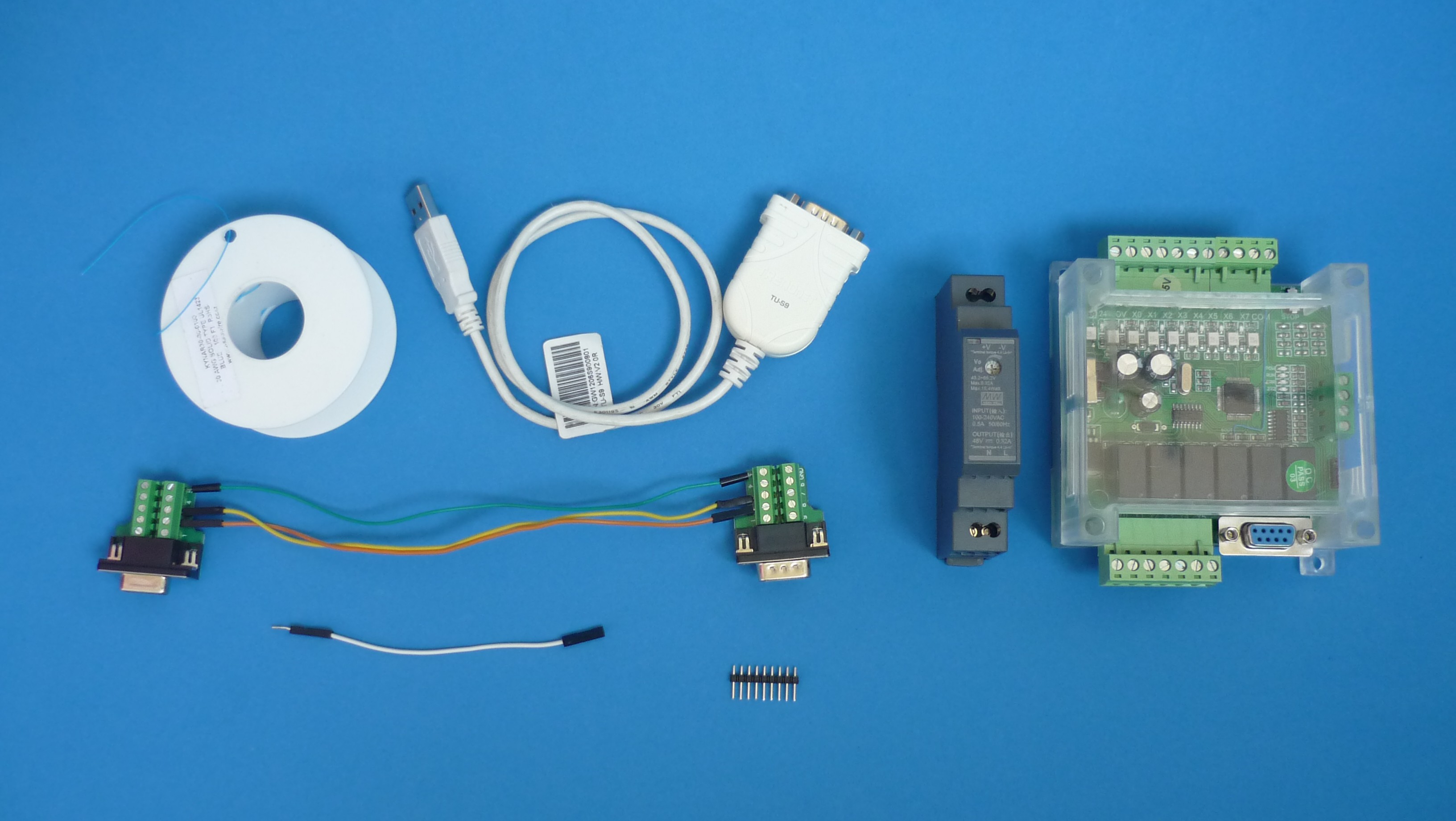
Parts used
COMPONENT DATASHEET - BUY LINK
- Industrial control board compatible with FX1N - buy link
- 24 V 15 W DIN rail mount power supply - buy link
- USB to RS232 converter - buy link
- DB9 solderless terminal connector - buy link
- 30 AWG UL1423 type PVDF wire - buy link
- Dupont cable jumper - buy link
Pinout for industrial control boards - repository
- Industrial control boards based on STM32 - stm32-industrial-control-boards
OPTIONAL COMPONENT DATASHEET - BUY LINK
- Magnifying double eye for jewelry - buy link
- USB digital microscope camera - buy link
- Digital multimeter powered by AA batteries - buy link
Reprograming
The aforementioned board, sports a STM32F103 microcontroller, so instinctively a footprint for a SWD programming header should be looked for.
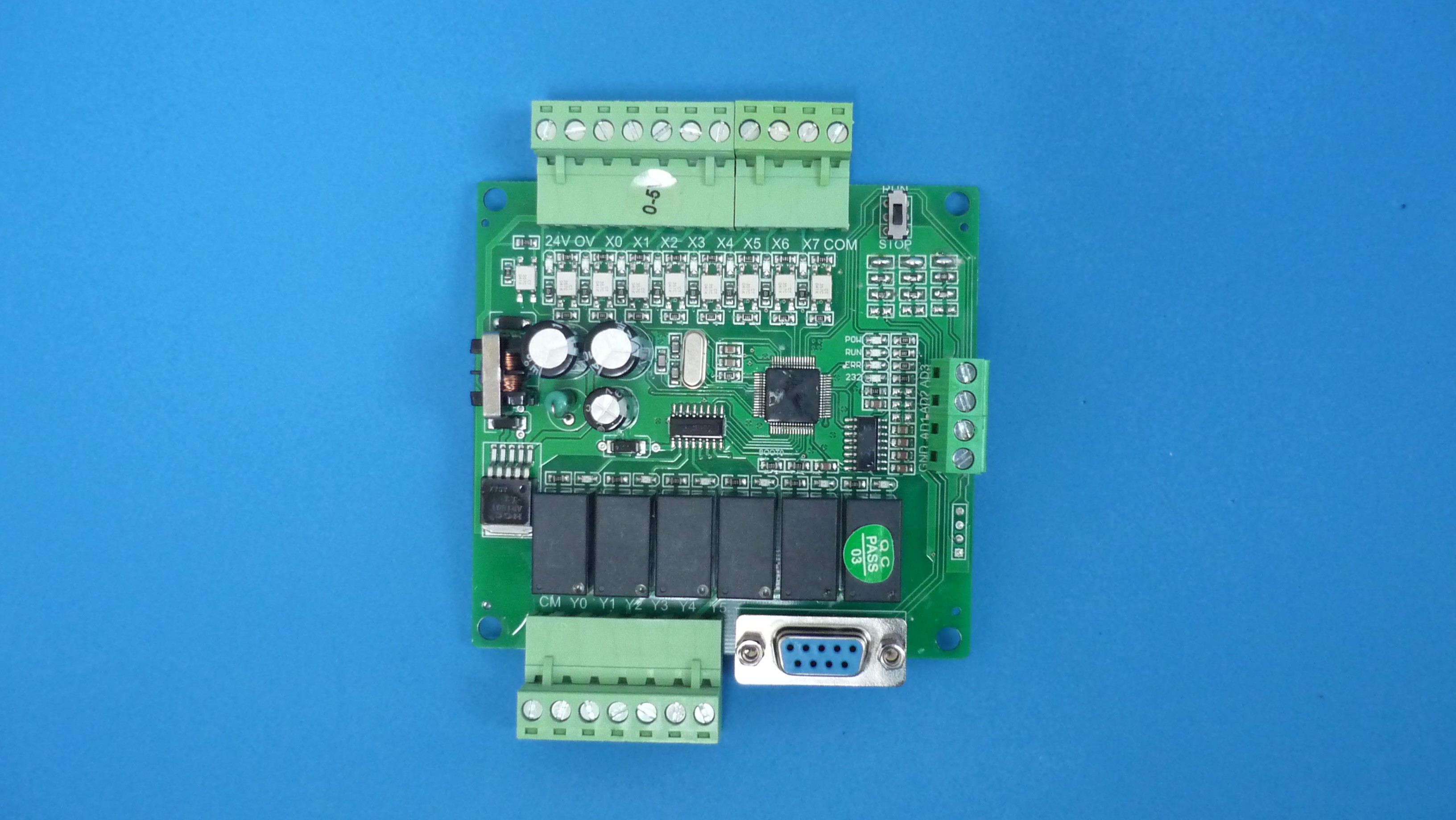
Possible programming header footprint at lower right
After following the tracks of this header, one pin was found connected to 3.3 V, another one to GND, but the other two pins were not connected to SWD pins on the microcontroller but to PC10 and PC11 pins. Starting the search from the microcontroller, there are no tracks from SWD or USB pins, so the only alternative available for reprogramming is through UART1 using the bootloader stored in ROM
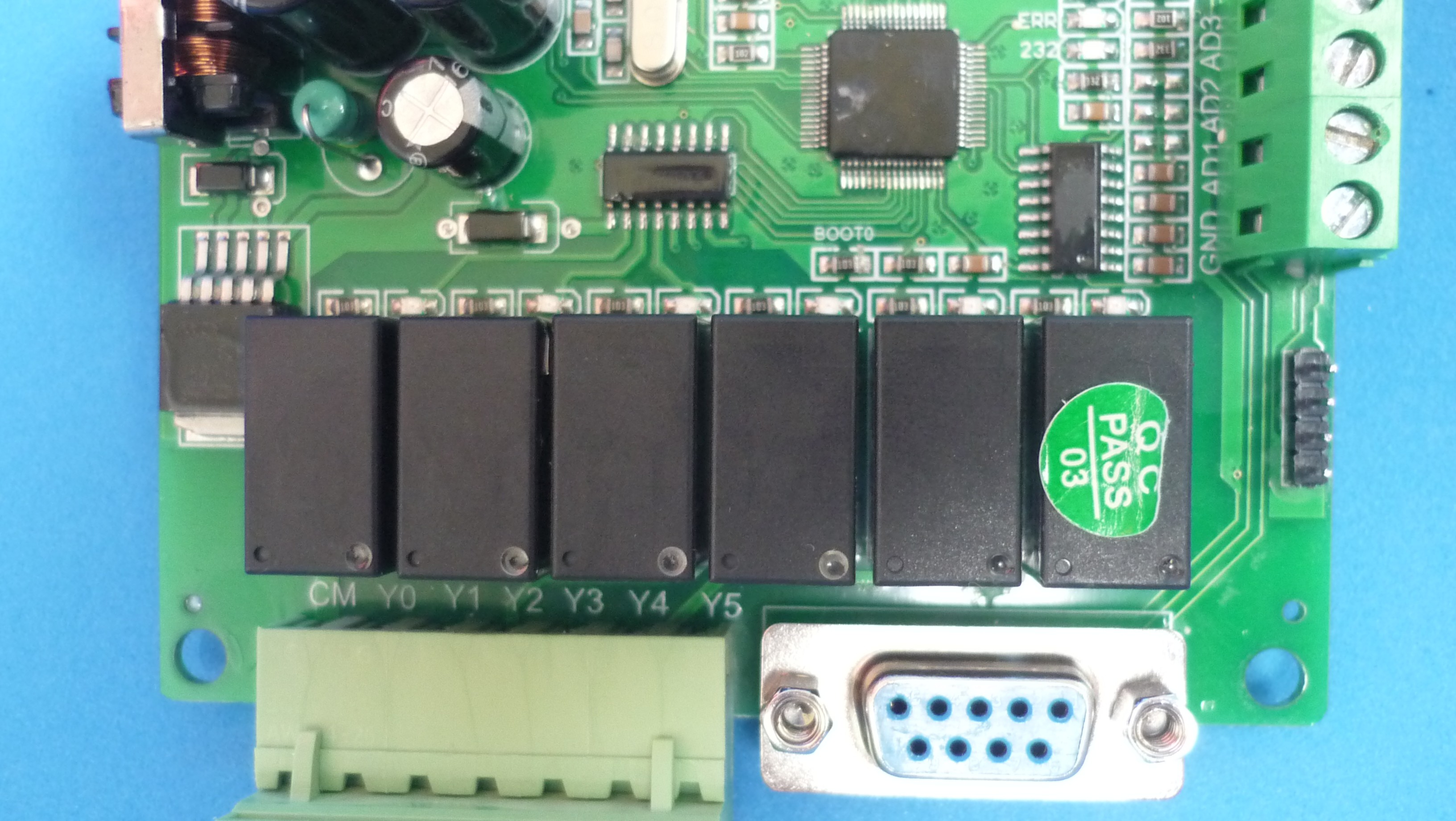
Serial port related components
Following the tracks leaving from the DB9 connector, they end in an unmarked chip, however, due to the nearby capacitors it is probably a MAX232 or equivalent. Following the tracks leaving from this chip they end in PA9 and PA10 pins of the microcontroller which are the UART1 pins.
Luckily in this board, the resistor which is connected to the BOOT0 pin is clearly marked on the silkscreen. To start in bootloader mode, a male header was soldered to the 3.3 V pad, and using a Dupont wire jumper, a temporary connection between BOOT0 and 3.3 V is made while the board is powered up

Method used for bootloader activation
Once the bootloader was running, STM32CubeProg was launched and communication with the microcontroller was verified. The chip was in read protect mode, so...
Read more »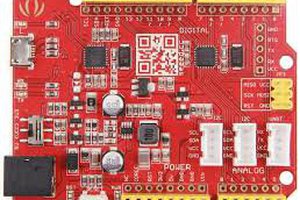
 Craig Hissett
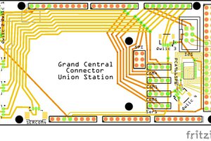
 bobgreenwade