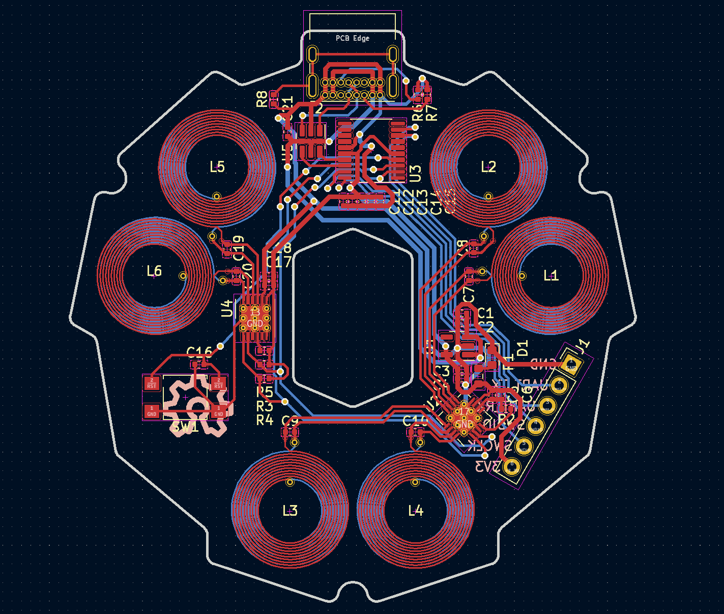
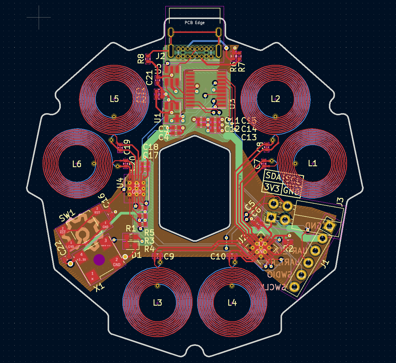
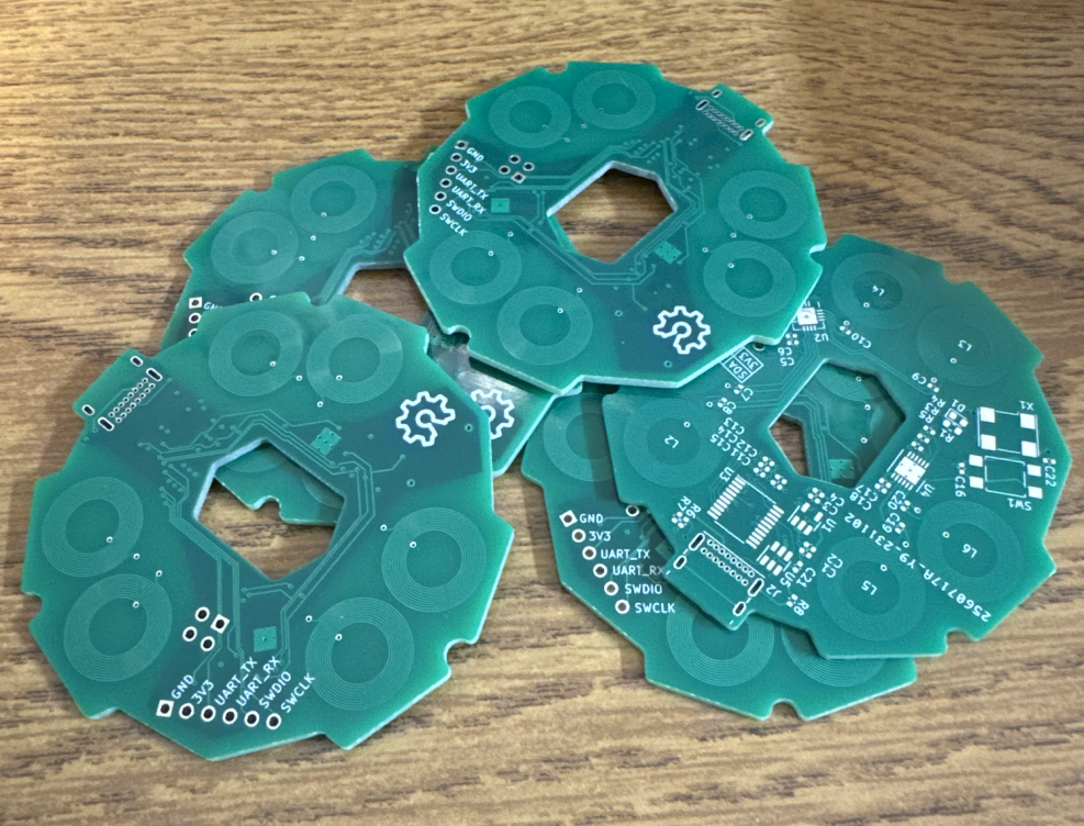
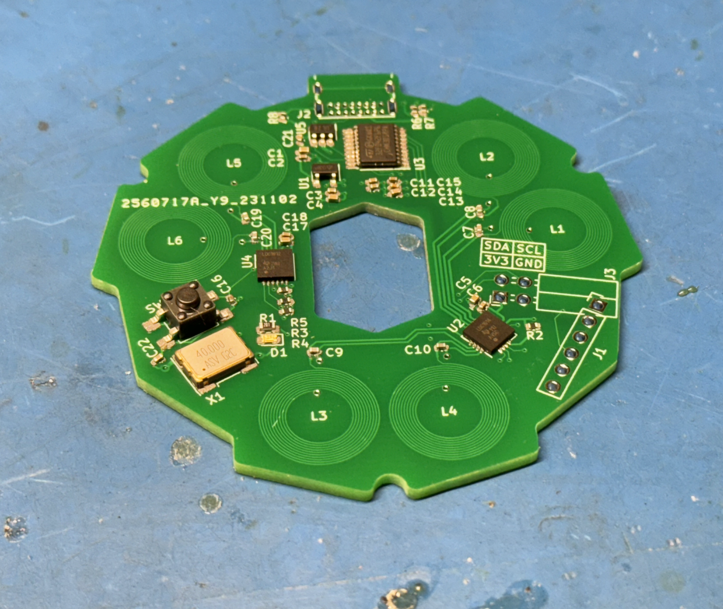
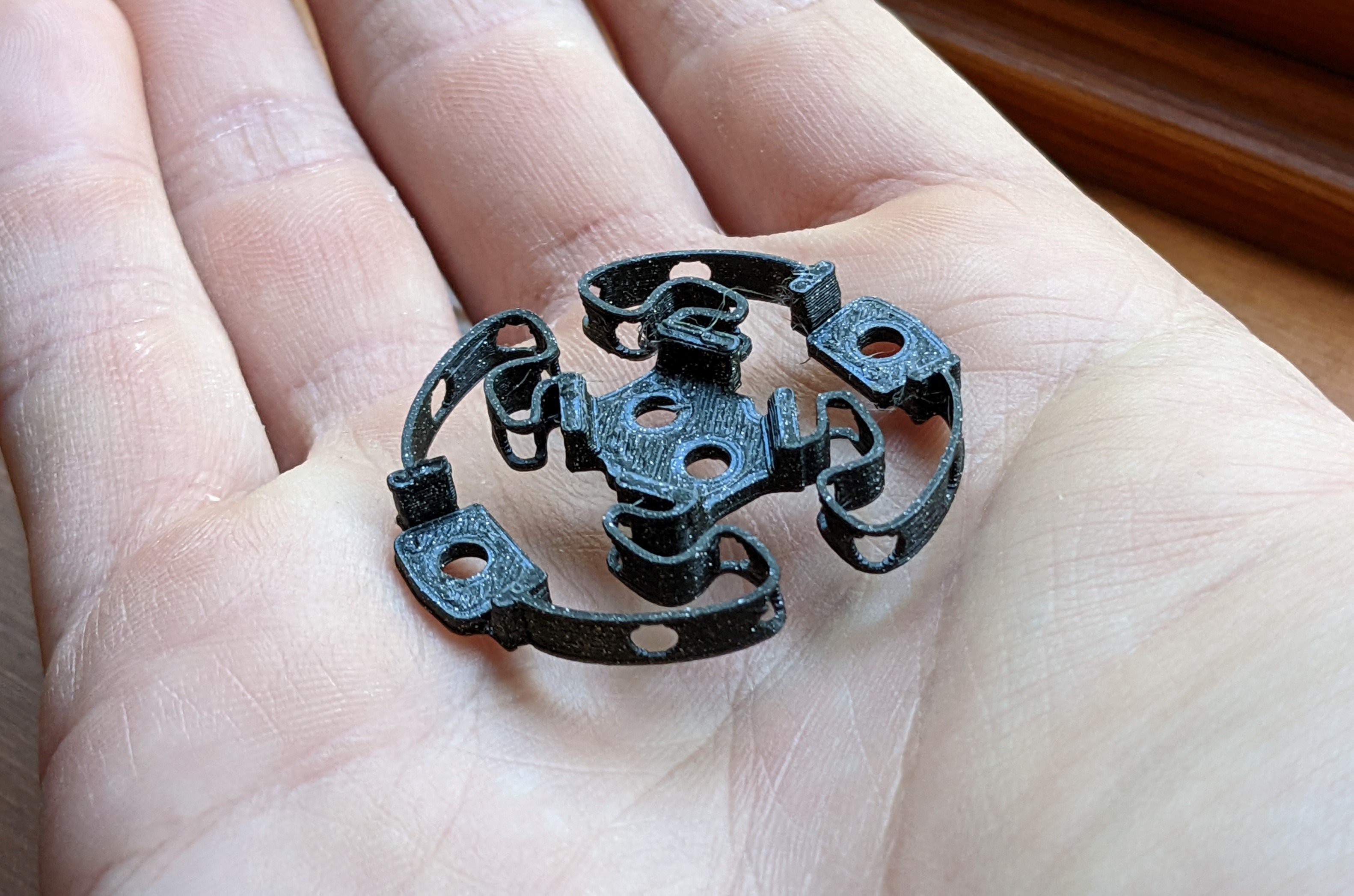
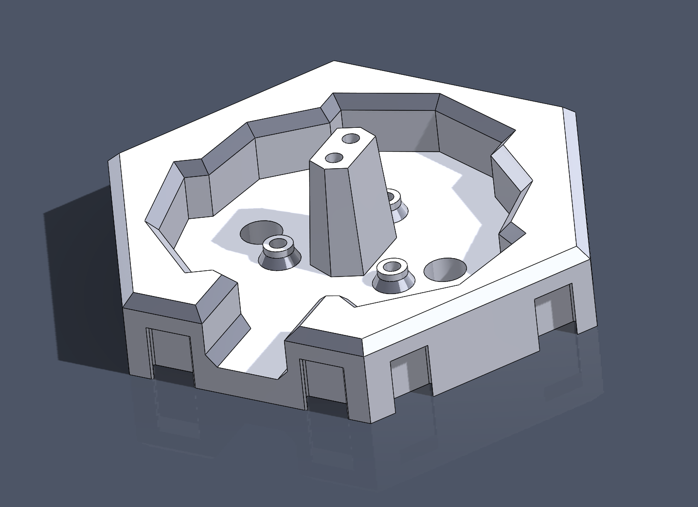
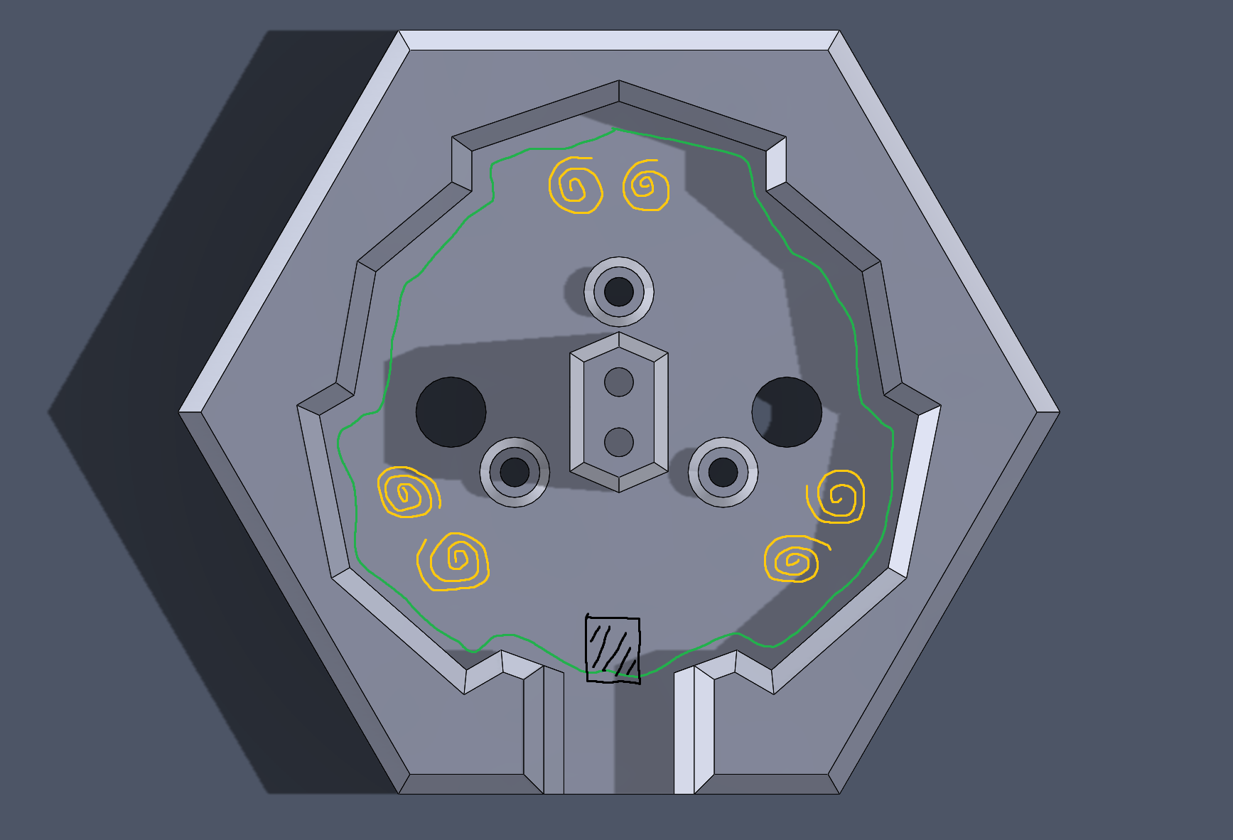
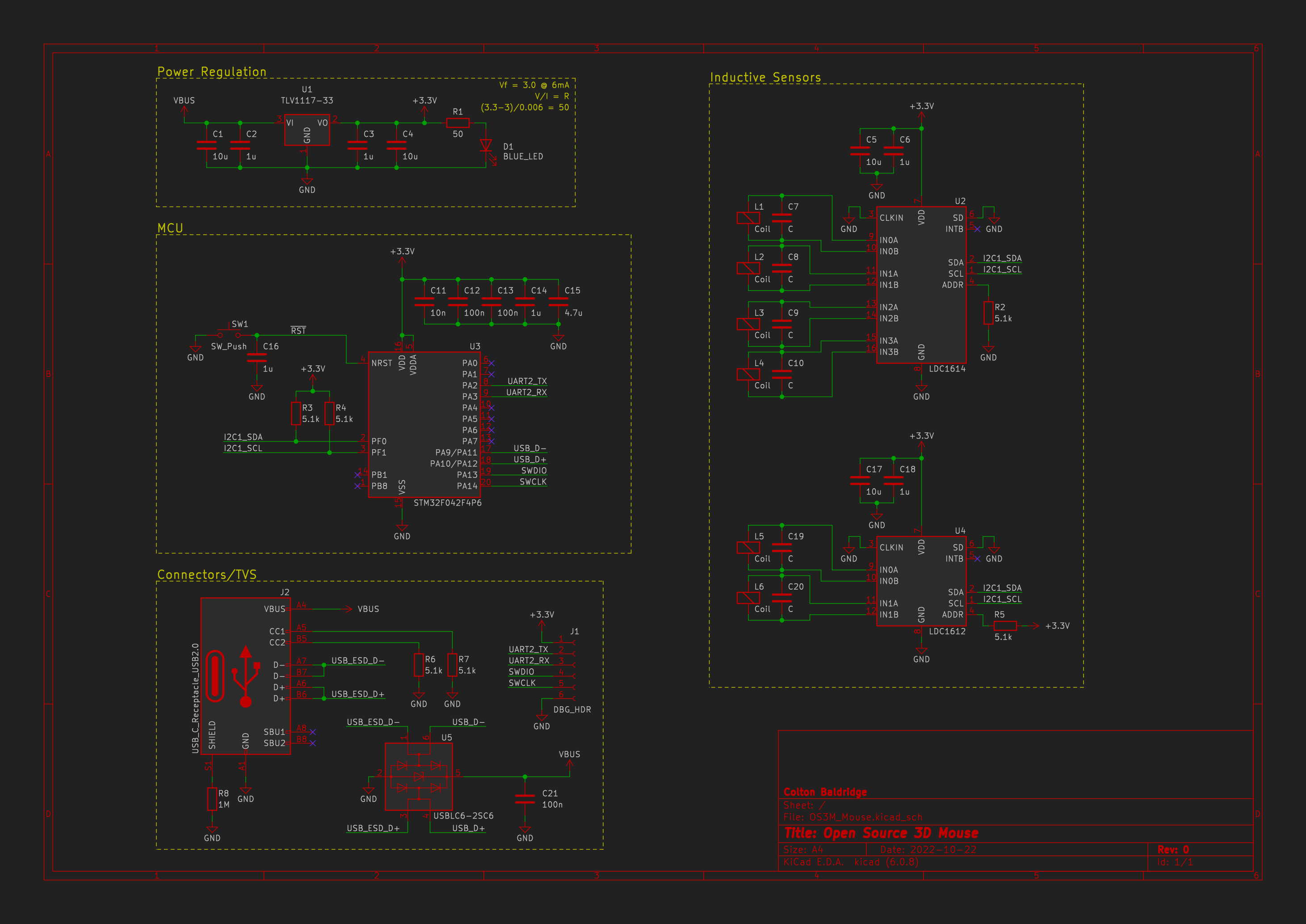
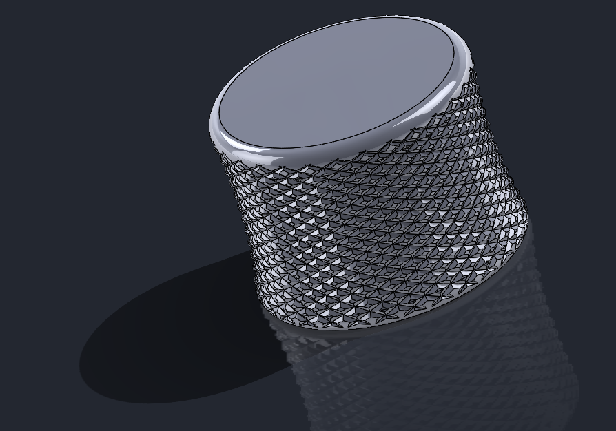
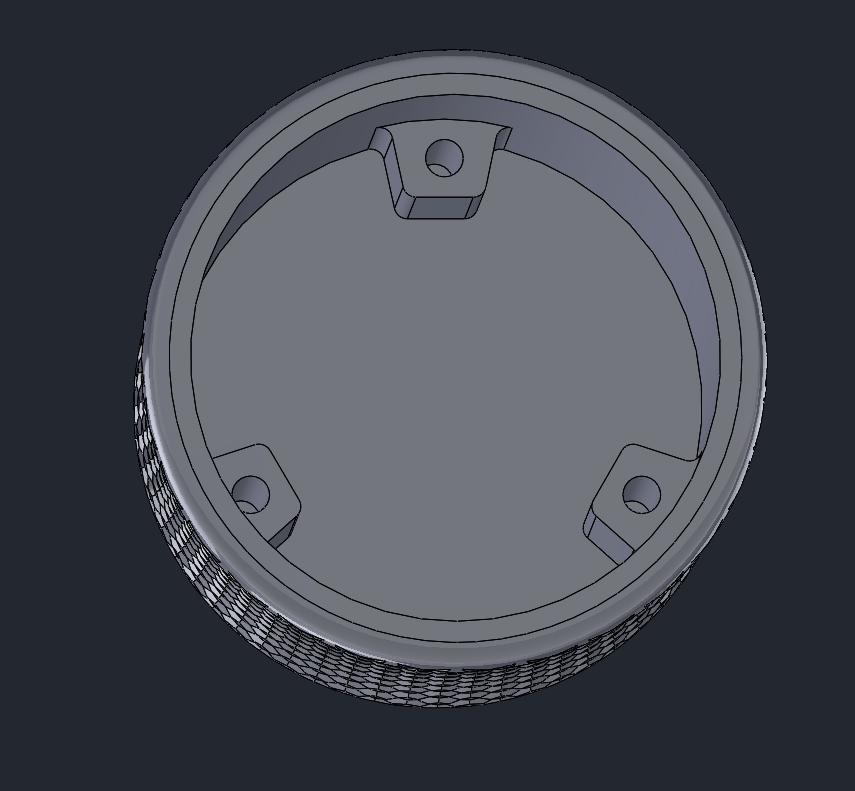
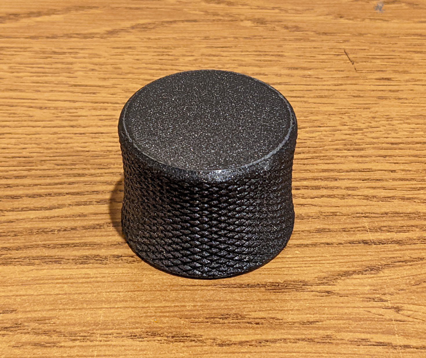
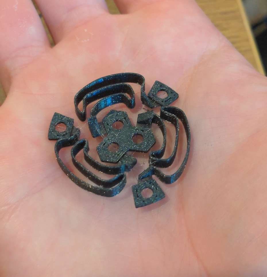
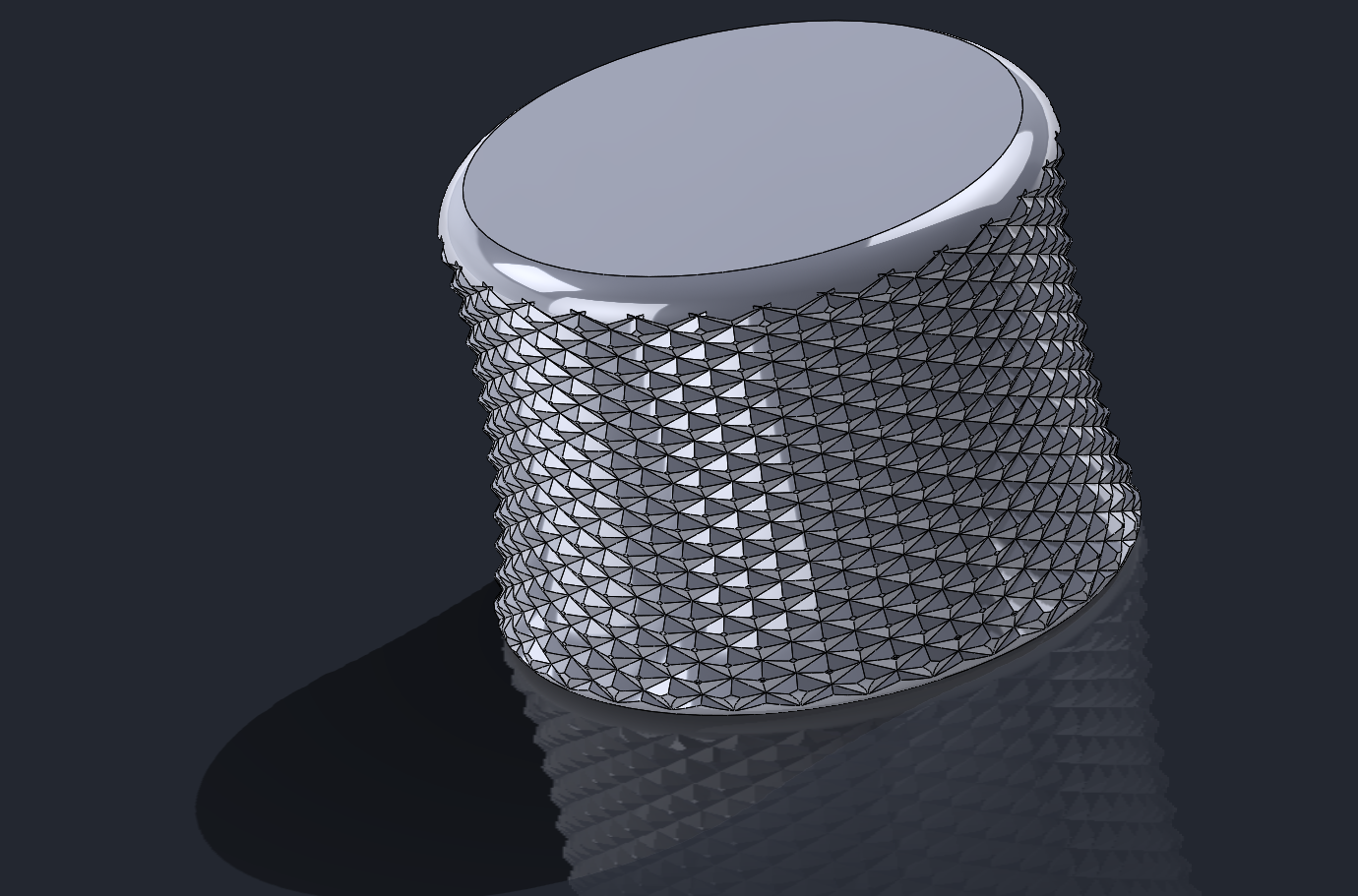
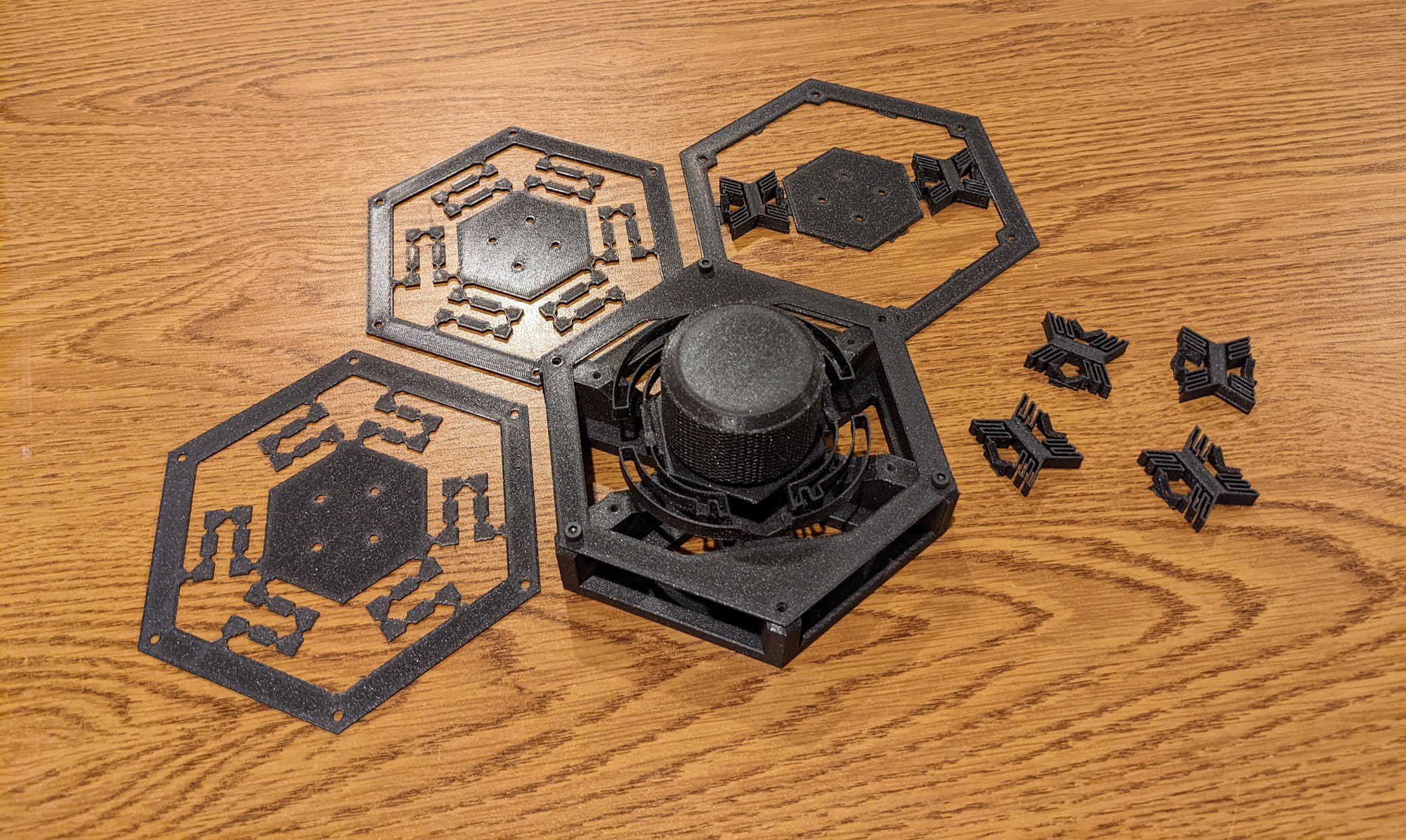
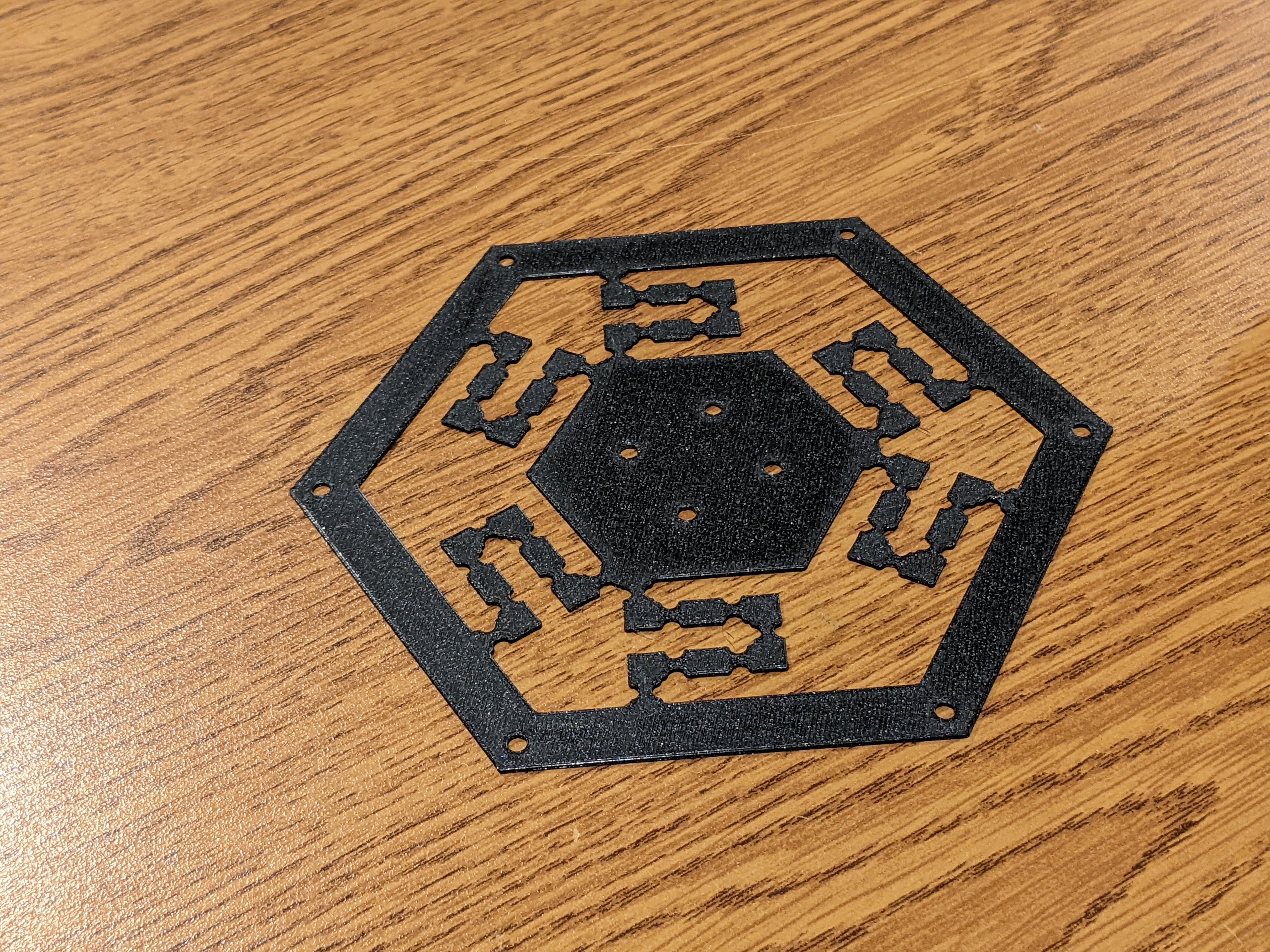
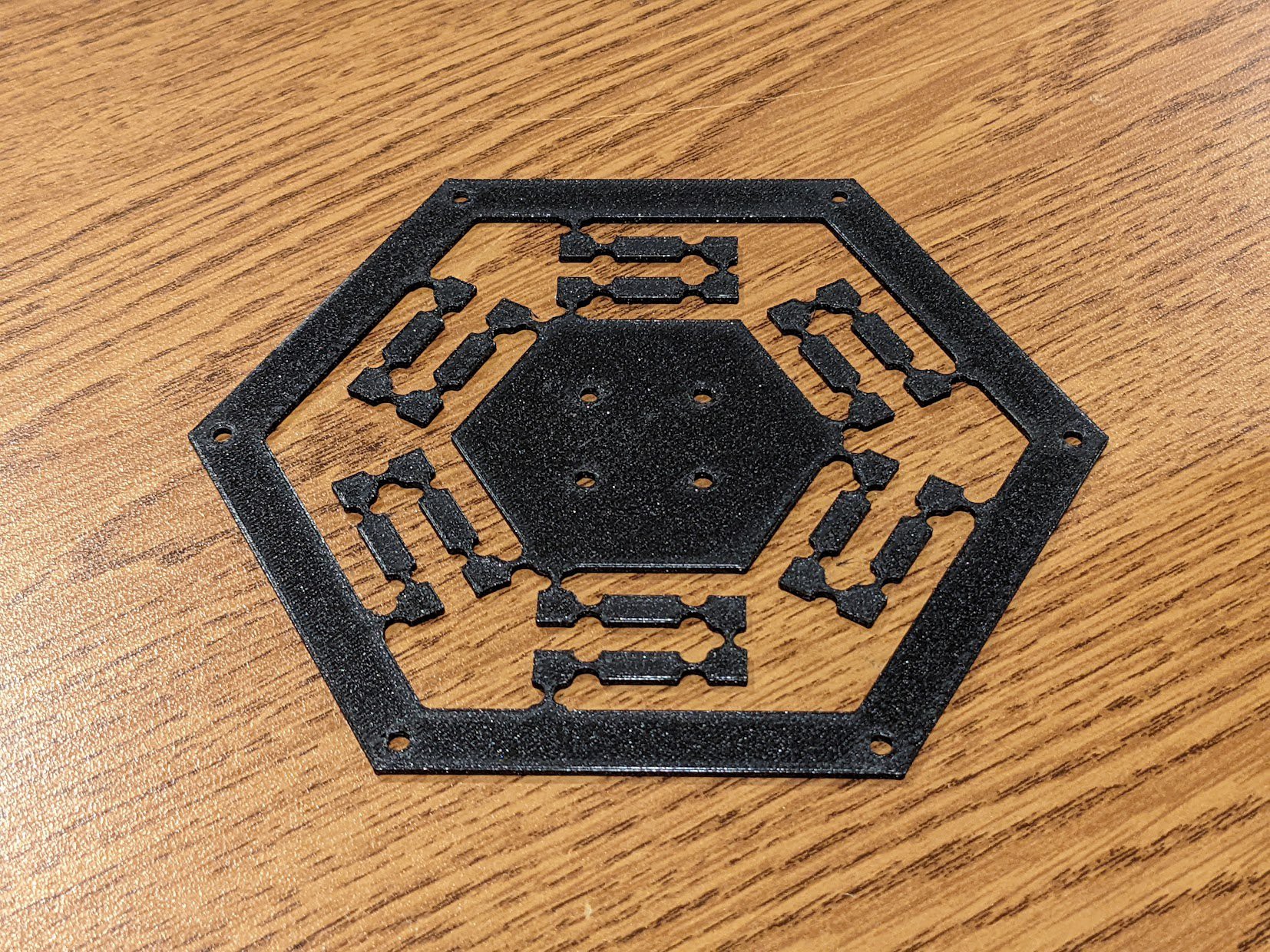
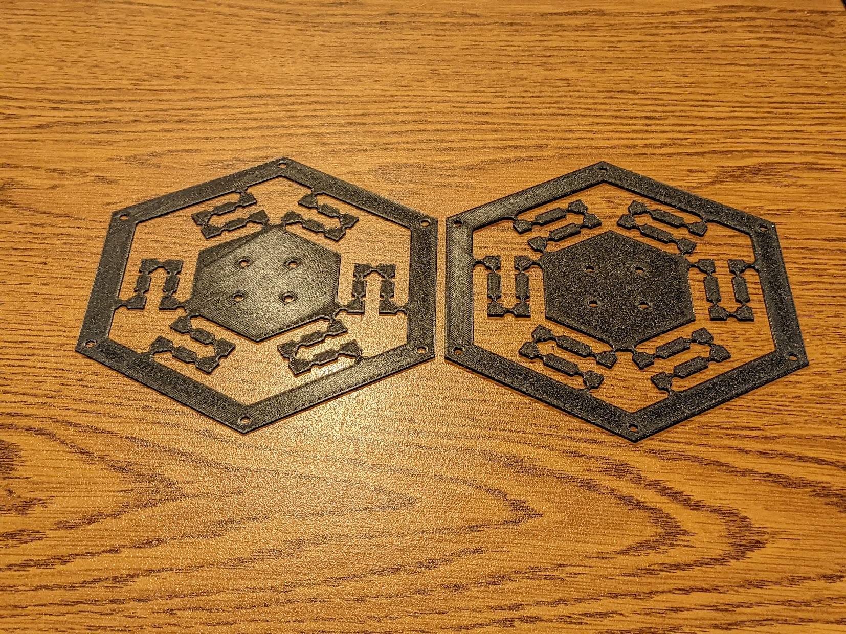
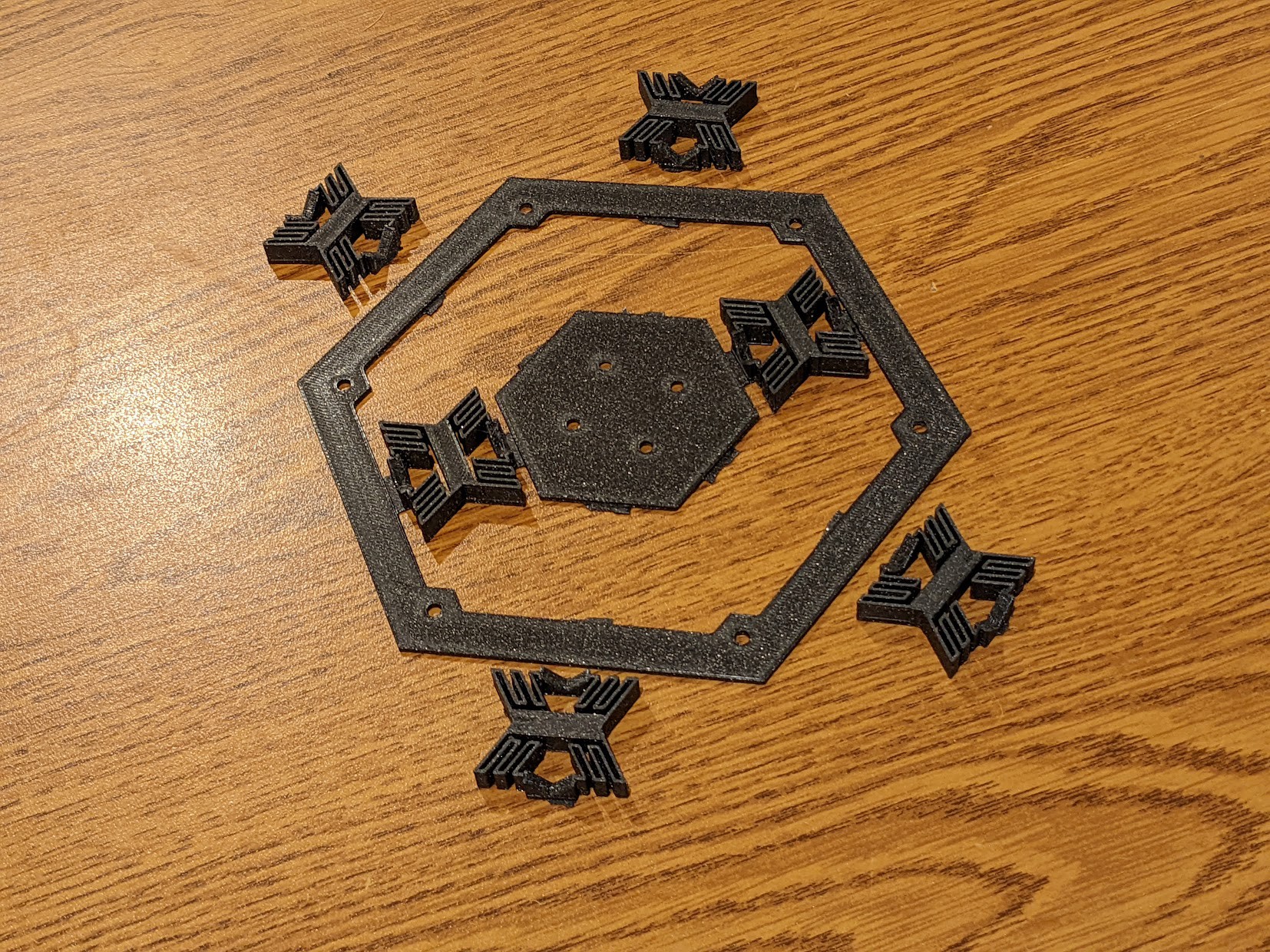
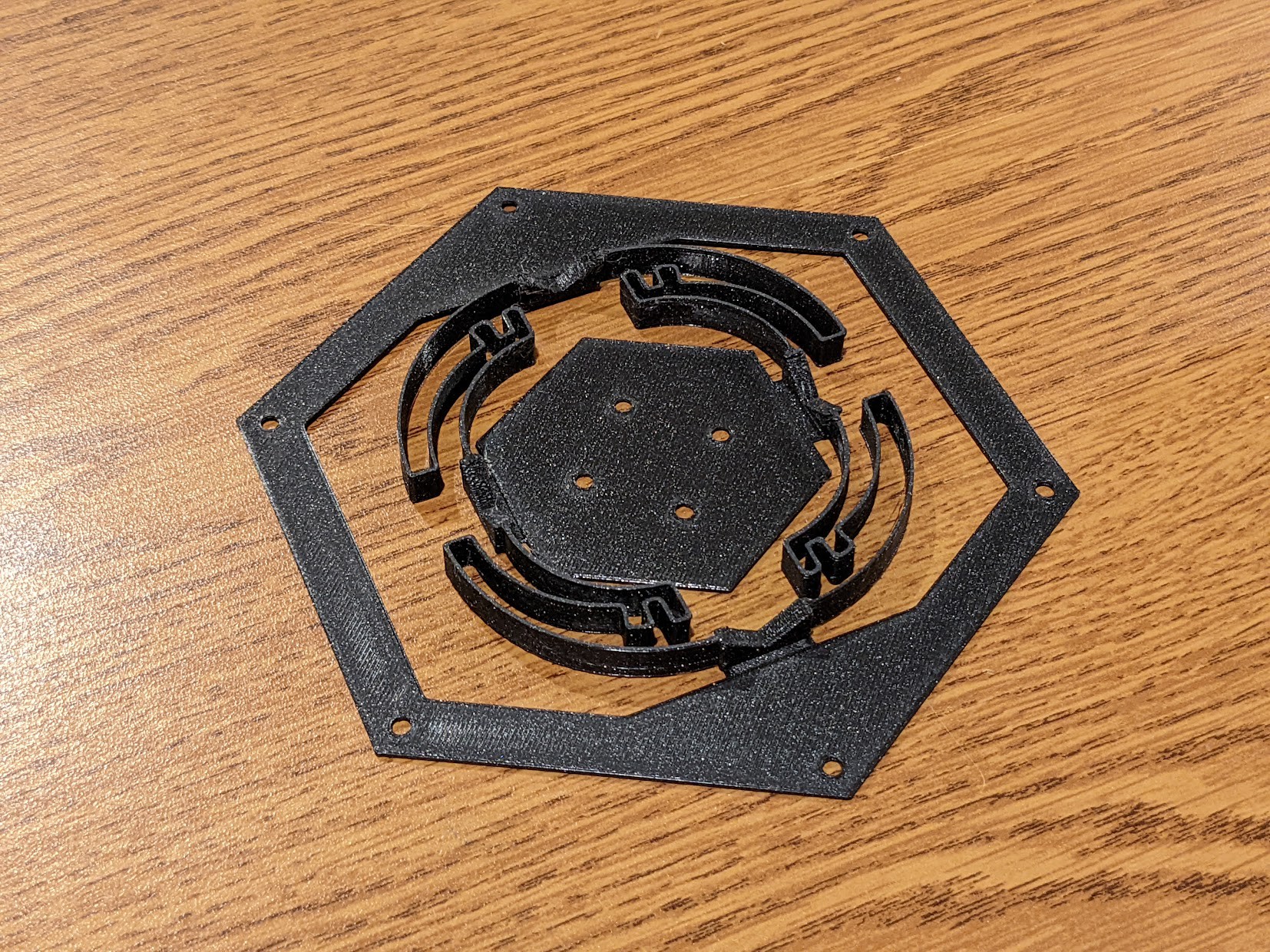
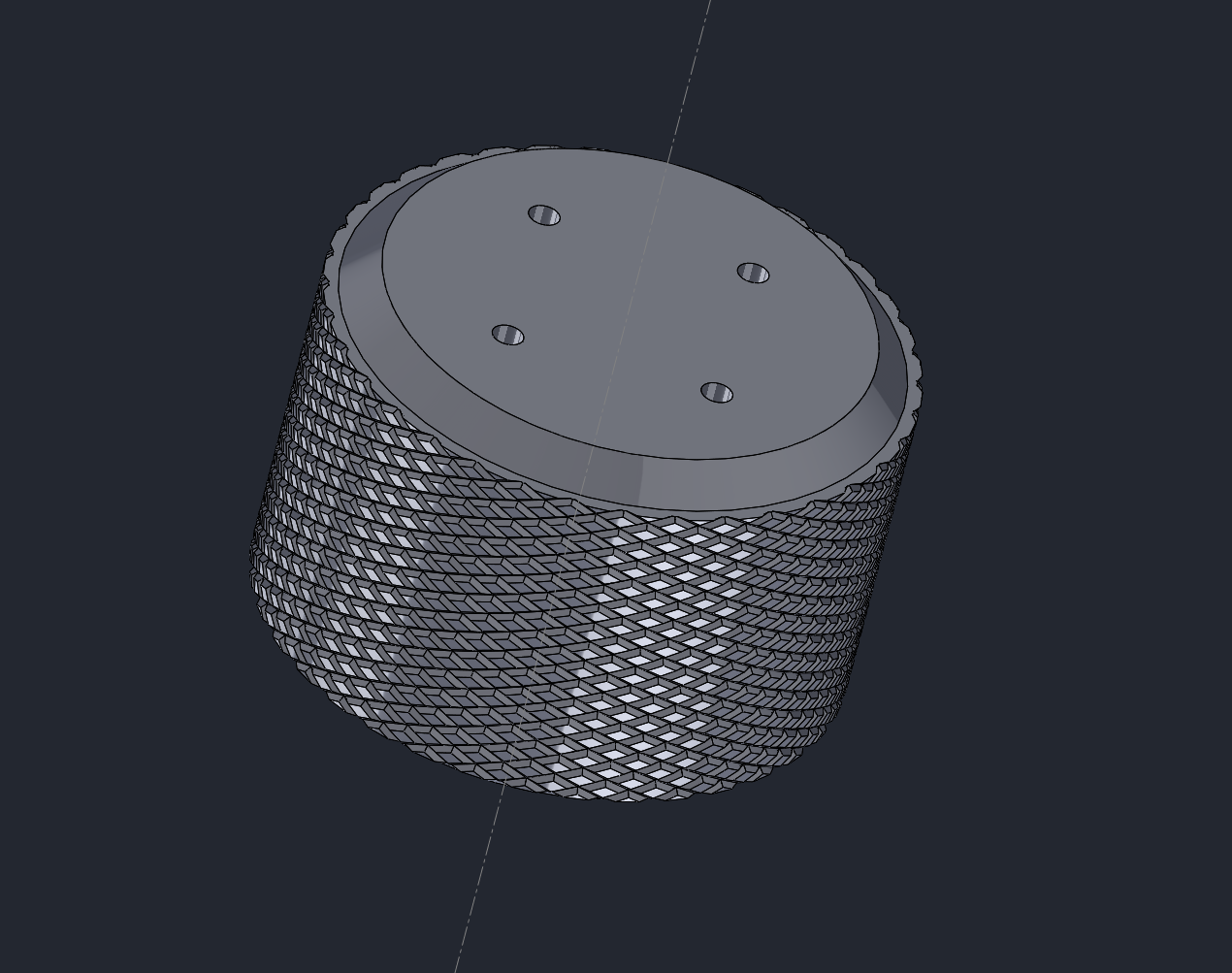
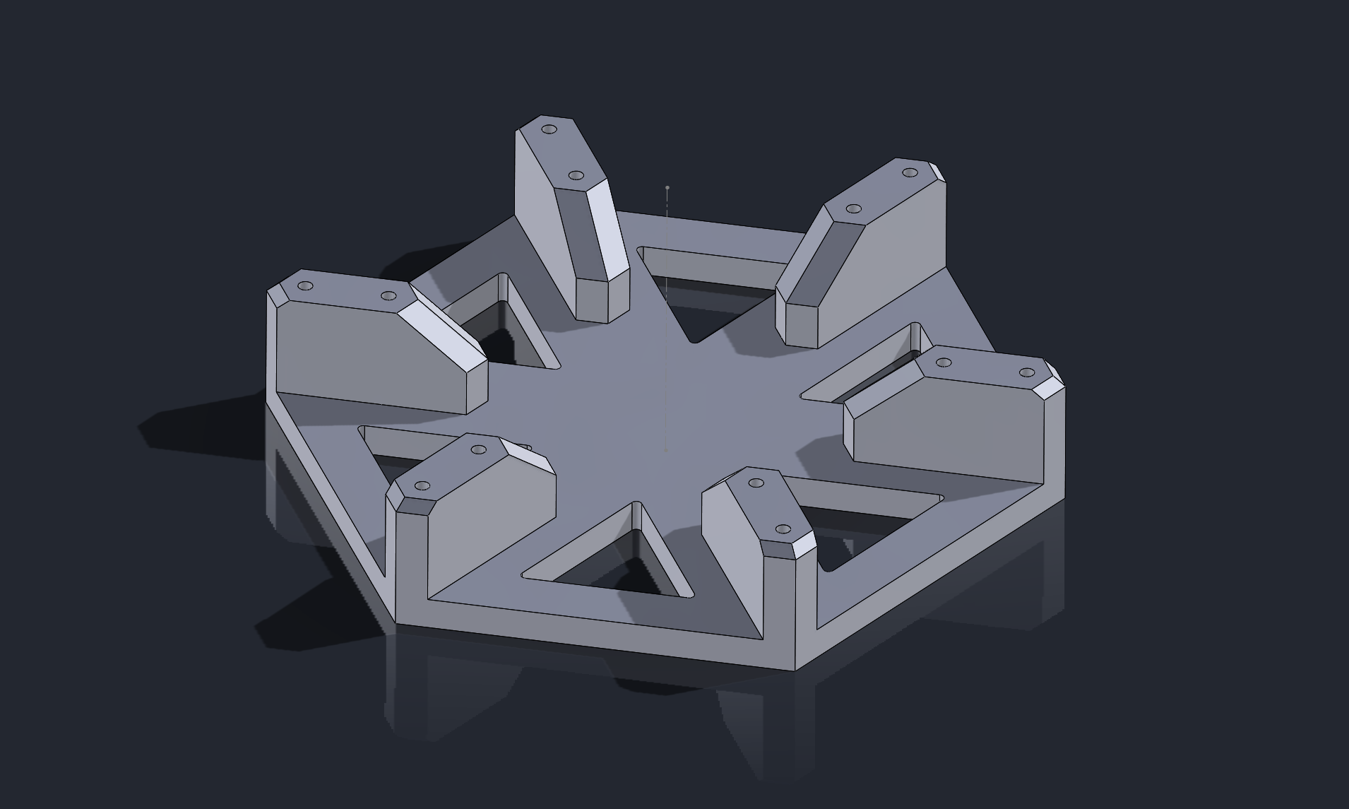
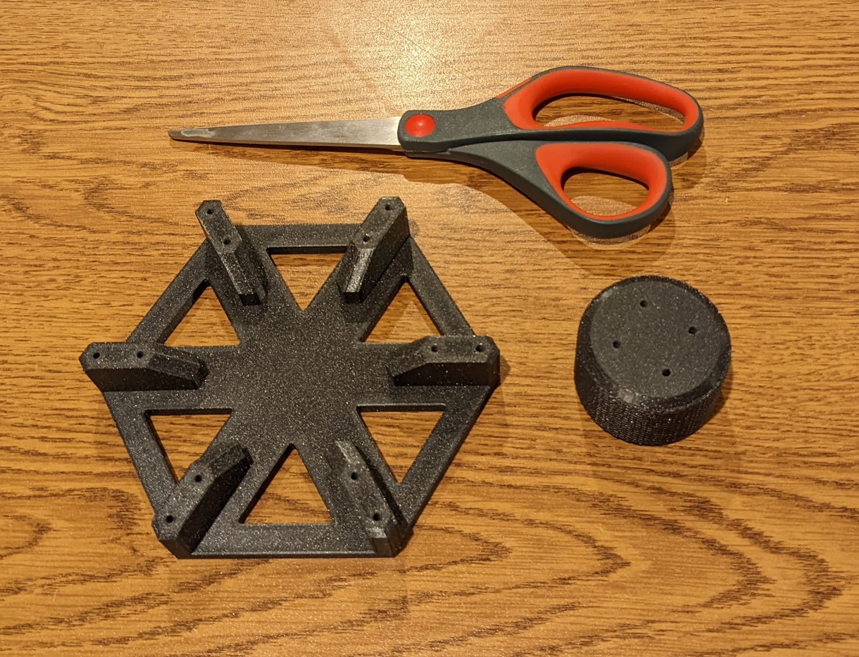
• Project Log 10: Awesome, a 3D mouse!

    colton.baldridge11/17/2023 at 06:39 7 comments

    Some of you might be wondering, if I had MVP 5 months ago... what happened to the OS3M mouse? And I'll tell you - my life got busy! Work on the project stalled for a few months following the last update. I reached a point where I knew a hardware revision was the right path, yet wasn't ready to take the plunge and actually do it with everything else I had going on. But, now that pretty much all daylight is gone here in Seattle, I don't feel bad about sitting inside after work! So, over the past month or so, I crafted the next revision of the OS3M mouse. It wasn't a major upgrade, but a necessary one nonetheless. I had the following list of improvements I knew I wanted to make after building and using revision 0 (the one in the MVP video):

    • accidentally ordered an 0402 resistor for R1 when the footprint was 0603
    • the power LED is too dang bright
    • I didn't place SDA and SCL test points
    • C11 - C15 were in a line that was painful to get in place
    • the 2n caps on the coils should be 1n for good parallel impedance
    • INTB should be connected on both LDCs for interrupt driven comms
    • I should use the STM32 with larger flash (in the same package)
    • add 40MHz external oscillator for increased accuracy
    • add an expansion header for future external GPIOs (or whatever your mind can imagine!)

    All things considered, revision 0 was a very good prototype that unlocked a lot of testing, but it wasn't good enough in my mind to be released to the public. That's where revision 1.0 comes in. It implements fixes to all of the above issues and (spoiler alert) is actually a viable release candidate! But first, I want to explain the needs behind a couple of the improvements I made.

    The 40MHz oscillator is probably the biggest change from the last revision, as it is the only major hardware addition. The reason for the oscillator comes down to noise. The LDC chips used to actually do the sensing rely on a reference AC signal and compare it with the resonant frequency of the coil circuits to get their output data. This means that any deviation in the reference signal directly couples into the output data as noise. Normally, this reference signal is generated by an RC oscillator internal to the LDC ICs, but TI also allows you to pipe in an external up-to 40MHz signal, which is what I have chosen to do. 

    The second major change is the addition of an expansion header. It breaks out GND, +3.3V, I2C_SDA, and I2C_SCL onto a right angle pin header. This should allow anyone to add something like the TI TCA9534 I2C I/O expander to the OS3M mouse, which could unlock even more functionality. Other ideas I've had are I2C LED controllers, I2C analog inputs (for potentiometers or sliders), or even I2C motor controllers. The sky is the limit.

    The design of revision 1.0 was actually a bit more involved than I initially expected. I did a full rip-up of all routing, and added in 2 more layers, making it a 4 layer board. Here you can see the revision 0 and 1 layouts side-by-side:

    You can see the clear addition of the expansion header in the bottom right, addition of the 40MHz crystal in the bottom left, and the movement of the 3.3V LDO to the top middle (where it probably should've been from the start). You can also see the orange ground plane and green power planes in the middle layers. I was slightly worried about adding the ground planes as close to the coils as I did (violates TI's recommendations), but this would prove to not be an issue. I sent the boards to good ol' JLCPCB and got them made with a stencil to boot.

    I squeegeed and soldered one up to use for development:

    And away I went.

    First development activities consisted of upgrading the project files to be compatible with the new, larger flash MCU. A task that actually wasn't as hard as I was expecting it to be. STM32CubeMX required a little finagling, but not too bad.

    I then set off on enabling the 40MHz oscillator, since it was only a single bit flag to turn on. And let me tell you... it...

    Read more »

  • Project Log 9: MVP!

    colton.baldridge06/21/2023 at 05:11 2 comments

    After long last, there might be light at the end of the tunnel for this project. Since the last update, I have been hard at work on the software front, both for the mouse and for the PC. At the point of my last update, I was so close, yet so far. I still had USB to implement and a Solidworks driver to write. For any hobbyist, USB is a BEAR. There is so much you have to learn... controlled impedances, differential pairs, the MCU's USB peripheral, descriptors, classes like HID, etc, etc. It gets out of hand really fast. On top of that, I had to figure out how to use the Solidworks API, which (thankfully) I already had some experience with back when I wrote that VBA script for FEA (in project log 4). 

    Setting off, I began with MCU code containing the algorithm I discussed last log and some serial transmission logic. And since I was already transmitting serial data, I figured the next easiest move would be attempting to add the USB CDC serial class. I thought this would be as simple as adding a few files provided by STM, but found that the example code was too big to fit on my microcontroller! After messing around with varying compiler and linker options, I was able to reduce the code size but it still wouldn't drop below the 16KiB that my microcontroller had. So, for the time being, I shelved USB.

    I then worked the other front -- the Solidworks driver. I went with C++ since that is the language I know best, and this proved to be not terribly difficult once I got everything setup properly. The lack of examples certainly hampered progress, but in general the online documentation was pretty alright. My biggest time sink was stumbling through what function calls I needed to make in order to emulate normal CAD mouse controls. This left me back with the bear... USB.

    Attempt 2 at tackling the USB implementation went a bit differently. I decided to dig deep, watching YouTube videos and reading sites like USB in a NutShell. I even started poking around the official USB 2.0 specification. The 650 page spec seems daunting at first, but once you've read enough summaries, the actual content doesn't surprise you with much, it just fills in the gaps. With this newfound knowledge, I decided to go right for the kill. The actual target for writing USB for this device was to make it a USB HID compliant joystick. That way, people can write Python, C++, or whatever to read data off this thing and not have to worry about a custom OS driver. (This also saves me work). Ready to fight hard, I went in expecting much pain and suffering as I selected the USB HID example from STM. However, much to my surprise, it compiled just fine, and when plugged into my PC, it just worked. Welp, so much for all that research. 

    (not true but still)

    The only real modifications I needed to make to the STM example were changing the HID report descriptor (which tells the PC what HID device the device is) and some buffer lengths. And with that, it was no problem! I loaded up the Windows game controller settings and bam, there it was:

    So with that, I modified the Solidworks driver to input data from the specific USB VID and PID of the of the OS3M mouse and whadayaknow, it works!

    So following up on last log's goals, I'll finally design those book holders (though I have since moved apartments and am not using that bookshelf the same anymore), and get to cleaning up code and releasing it. This is where I'll need some help from you all (the community). I've never released an open source project and the licensing situation is daunting to say the least. I'll put in my best effort to make sure I abide by all the licenses of software I'm using, but can't make any promises that I'll do it right. Please contribute and help me out!

    Thanks for reading!

  • Project Log 8: It Finally Works!

    colton.baldridge04/02/2023 at 07:59 1 comment

    Picking up from the last log, I had good working hardware that was able to send raw data from the LDCs to my PC, but I wasn't sure what to do with that data. In comes the software. I knew this problem would be a hard one. In one of my earlier project logs I mentioned using the Stewart platform as a kinematic model for the device. 

    This sounds great on paper until you try to go and actually solve the direct kinematics of a Stewart platform. In direct kinematics, you know the lengths of the legs and try to solve for platform position, rather than inverse kinematics where you know what platform position you want and solve for leg lengths. I am but a humble electrical engineer and this world is extremely foreign to me, but I dove in anyways hoping to find some example code or something that I could port to my application. All I found was disappointment and papers with names such as "Forward Displacement Analysis of a General 6-3 Stewart Platform Using Conformal Geometric Algebra". Much to my and probably your dismay, I have no interest in learning all the prerequisites necessary to even begin parsing a paper like that. And so... the project sat. I thought more and more about it, but wasn't sure who to reach out to for help with this problem. 

    And funny enough, my rescue came from the last place I expected it... someone doing the same project as me! When I first started this project several months ago, I thought I was alone, but just in that short time, at least 3 other projects with the same goal have popped up. My solution came from the SpaceFox, which claims to be the first true DIY 6DOF spacemouse. (and while my pride is a bit hurt, I think he may be correct). I have no idea how he came up with his solution for kinematics, but they seem fairly intuitive and would be easy for your average microcontroller to compute. I have taken these kinematics, made some slight modifications, and implemented them in my code. Much to my surprise, they worked! It took a bit more debugging than that makes it sound, but still! No nasty univariate polynomial of the 40th order! After seeing this, I felt reenergized about the project and started making more progress (including publishing the last update). 

    My next goal was to visualize the translation and rotation. I dug in more to see what would be necessary to get the serial data to actually interface with Solidworks. I didn't like the answer: it seems like I will have to write a custom C++ application in order to do the interfacing. I wasn't feeling up to that to start, so I did the next best thing - write something scrappy in Python! If you've never heard of it, there's a wonderful game engine known as Ursina that's written to with nice Python bindings and is dead simple to get started with. I merely glued together pyserial and Ursina with the script below to create a working result! 

    import serial
    from ursina import *
    
    app = Ursina()
    ser = serial.Serial('COM5', 115200)
    
    cube = Entity(model='cube', texture='white_cube', scale=2, collider='box')
    
    
    def my_update():
        line = ser.readline()  # get the serial data
        line = line.decode('ascii').rstrip().split(', ')
        coil_data = [float(i) / 200 for i in line]  # break apart the data, scale it down
        print(f'vals: {coil_data}')
        coil_data = [0 if abs(i) < 0.2 else i for i in coil_data]  # filter out small drift
        x, y, z, rx, ry, rz = coil_data
        cube.position = cube.position + ((x - rx * .3) / 2, z / 14, (-y - ry * .3) / 2)  # apply rotational correction
        cube.rotation = cube.rotation + (rx * 1.5, rz * 2, -ry * 1.5)
    
    
    cube.update = my_update
    EditorCamera()
    
    app.run()

    Check it out!

    As you can see, it works!!! But, it is certainly not without its issues. If you look closely at the script above, you'll notice that the position data is having rotational correction applied to it. I'm not sure what the technical name for this is, but I imagine it's something like "inter-axis interaction". My understanding so far is that...

    Read more »

  • Project Log 7: Hardware Complete(ish)!

    colton.baldridge03/31/2023 at 01:57 0 comments

    Wow, long time no see, huh? To make a long story short, my life has been pretty hectic since the last log I posted, but lately I've finally gotten some time to work on this project.

    Picking up where I left off, I had just received the PCBs and was getting ready to do some bringup - and bringup I did! The first board I populated was meant to be for dev test only. It lacked both a MCU (hadn't arrived yet) and a USB port (no point without the MCU). It did have all the other features though, like the LDC chips, voltage regulator, and a slightly melted reset button. Glamor shots:

    I used this board in combination with an Arduino to do some checkouts on the LDCs. 

    In doing so, I found a couple mistakes I made with this board:

    1. The footprint for the current limiting resistor for the LED (R1) is 0603, while the actual part I ordered is 0402
      1. This was not a big issue as I was still able to verify the voltage regulator worked with a multimeter.
    2. The capacitor I chose for the coils was too big (2nf) and pushed the parallel resistance of the coil very low.
      1. This was a big issue, as the LDC chips have a minimum parallel resistance spec that needs to be met. I was able to compensate for this error on one coil by enabling the 'high current drive' feature on the LDC, but this unfortunately that feature is only available when you're driving 1 coil, not multiple. 

    All in all though, the dev board served its purpose quite well and enabled me to prove out a number of systems. By this point I had finally received the MCU I planned to use and it was time to tackle the real deal. I headed back to the soldering bench, populated another PCB, soldered it up, and was ready to get to programming. 

    Unfortunately, the universe had other plans... I noticed when I was spreading the solder paste that it was a bit thin. This actually led to several shorts on the board. The reset button would short power and ground, one LDC has a channel shorted, and the current limiting resistor had tombstoned. After fixing all of these issues, however, it did successfully power on. I plugged in the MCU to my computer and BAM, the bootloader for the STM32 popped right up, which meant the USB implementation was good. NICE! So naturally, I kept rolling and opened up STM32CubeIDE to get to programming. I setup my IOC file to enable all my peripherals that I needed, typed up a basic Hello World program and told it to build aaaaand

    tools\arm-none-eabi\bin\ld.exe: os3m_dev.elf section `.text' will not fit in region `FLASH'
    tools\arm-none-eabi\bin\ld.exe: region `FLASH' overflowed by 22292 bytes

     ...oh no. That's not good.

    Turns out, the MCU I bought did not have enough flash space to fit even my Hello World program. Like way not enough (16kb). Unsurprisingly, the HAL to operate the USB peripheral is quite large, but I didn't have a good feel for just how large it was before I decided on my specific MCU. (I could've done all this compiling ahead of time and saved myself some time, but alas, hindsight is 20/20). I tried changing the optimizer settings a bit to see if it could reduce the code size a bit, and it did, but ultimately was not enough to help what was a pretty hopeless situation.

    At that point I decided to pivot to try to do as much as possible with the hardware I had. The HAL for UART and I2C comms was much smaller and did fit into the flash section so I focused on trying to get something working. I first started with Hello World but this time using serial. This fit no problem, and worked just fine. I then ported over the arduino library I had been using for the LDCs, stripped it way down to only the subset of functions I wanted, and tried to implement it. Now, you might remember what I said above about the parallel resistance of the coils being too low for the LDC to take multiple coil measurements. The way you decrease the parallel resistance is by reducing the capacitance...

    Read more »

  • Project Log 6: Release the PCBs!

    colton.baldridge11/06/2022 at 00:48 5 comments

    Ah, home at last. After spending so long in the mechanical world, I almost felt disconnected from my electrical roots (ba-dum-tss). Corny jokes aside, it has been really nice to get to dig through datasheets, lay down some traces, tear through app notes, and do many other things that I'm used to. 

    So starting off with the component selection, I knew I needed a few things:

    • USB Type C (because it's the hip thing now)
    • A microcontroller with USB support
    • TVS (transient voltage suppression)
    • TI's inductance to digital converters
    • And a regulator to power all of the above

    The first one was easy, I just went with a generic USB 2.0 type C connector that already had a part made in the KiCAD library, and was in stock at digikey. It also had the advantage of being through-hole. I've had some experiences with SMT type-C connectors in the past and they were not positive ones.

    The MCU is the heart of most hobbyist PCB designs and this one is no exception. I had a few requirements when looking for one to support the OS3M mouse: low cost, low passive count, good developer experience, and in stock. To be transparent though, I do have previous experience with STM32s, so naturally I started looking there first. There, I found the SMT32F042 line of parts, which satisfy all of my requirements. A key selling point of this product line is that they support "crystal-less" USB. This is important because most MCUs need an accurately tuned external crystal to work with the tight timing requirements of USB, but not this one! To quote the datasheet:

    > The STM32F042x4/x6 embeds a special block which allows automatic trimming of the internal 48 MHz oscillator to guarantee its optimal accuracy over the whole device operational range. This automatic trimming is based on the external synchronization signal, which could be either derived from USB SOF signalization, from LSE oscillator, from an external signal on CRS_SYNC pin or generated by user software.

    This is wonderful for me, and anyone else who wants to use this mouse, as it means lower component count, less things to mess up when soldering, and lower cost. Additionally, I already have experience using STM32CubeIDE, ST's poorly named but decently functional IDE. It's Eclipse-based and so there are plenty of plugins and problems are readily google-able. 

    TVS for this board was a requirement due to it being something people touch a lot. It's highly likely that at some point when plugging in an OS3M mouse, the USB port will take one or more ESD (electrostatic discharge, a static shock) strikes. Conveniently, the MCU I chose was already USB-focused, so it was relatively easy to find ST's app note on USB guidelines from which they recommend the USBLC6-2 IC. This monolithic chip is a device purpose built to save our bacon from spicy static shocks.

    As mentioned in the last post, the sensing solution I've been betting this whole project on is inductance to digital conversion. In this realm it seems TI reigns king, and I know first hand that the products they make are quality (summer internship, sweet place to work btw). Since I needed 6 coils worth of sensing capacity, and I didn't know the degree of accuracy I needed, I went with a pairing of their higher end (26-bit resolution) LDC1612 and LDC1614 chips. These guys come in nice small, but not unsolderable, QFN and TSSOP packages. Another wonderful aspect of TI is that their datasheets, web resources, and app notes are top notch. Here, I used their coil designer webapp in combination with their app note on sensor design to actually perform the design of the PCB coil I integrated.

    Lastly came the regulator, and here I chose the simple solution - a linear regulator. Since I was only going from 5 to 3.3V, the energy needing to be burned off as heat wouldn't be all that substantial and I could keep everything nice and compact. Going to a switching architecture would only have needlessly complicated things.

    With the above key...

    Read more »

  • Project Log 5: Exit Mechanical, Enter Electrical

    colton.baldridge10/23/2022 at 18:15 0 comments

    True to my last log, I ended up only making a few (ahem, more like 7, but who's counting?) more revisions to the flexure before calling it good enough. Unfortunately, in doing so, I realize that what I've created is more of a 3D printer torture test.

    As you can see, the bendy parts of the flexure are a mere 0.5mm thick, with several holes placed in them. My Prusa mini has actually been printing these with a 100% success rate (lots of iterations on hole location and other factors) but I worry about releasing this for others to try to print, as I've spent a lot of time with less reliable printers and know the pain of failed print after failed print. 

    This has inclined me to start considering alternate solutions. I'd like to still keep the flexure 3D printed, but if I'm unable to come up with a reliably printable design, swapping to metal springs might be the easy way out. 

    For now though, this god-forsaken solution is going to be the one to stay, as I really need to keep moving forward with the project. I don't want to fall into the trap of perfectionism, and I'd really like to get to my bread and butter -- electrical design.

    To keep moving, I started thinking about what features the final base should have. Up to this point I've just been using a small spire of an adapter that has been taped down to my desk. But, for this to be a real product, I'd need the base to be able hold a PCB, and it would be especially nice if it could look good while doing so. Additionally, I've been thinking more about what the capabilities of this mouse should be. Something that I think is really interesting on the commercial solution is the inclusion of buttons and even a display on the highest end model. This inspired me to add an additional requirement that this base should include some sort of modularity. I've been inspired by a lot of open-source mechanical keyboards in the fact that they often break out bonus functionality using I2C over a headphone jack. I think that would be super cool to support accessories like the ones mentioned above. I probably won't start with including it, as there is a lot of technical risk already associated with my current electrical approach, but once I buy down some of that risk, I'll roll in an exposed I2C bus on a future revision.

    And after having these many thoughts, I designed the first revision on the base:

    To understand the design I have here, you first have to understand the plans for the electrical side of this mouse. My thinking is that I can use some of TI's super cool inductance to digital sensors to read the position of  metal objects within the knob. Using 6 coils/sensors (needed to determine the 6DOFs) in 3 pairs, I can use the math associated with a Stewart platform to back out the position/rotation of the mouse, like so:

    An example of six-DOF Stewart platform. DOF: degree of freedom. | Download  Scientific Diagram

    The only variables here are the lengths of the actuators, so if I can back out the kinematics of the system, I can determine the translation/rotation of the mobile platform (in our case, the knob). This wondrous MS paint drawing shows roughly the plan for the PCB:

    And with that, I've set away at making the PCB. The schematic is actually already mostly done, so I'm hoping to have hardware in hand sometime in the next couple weeks (we'll see about that timeline, lol).

    As an added bonus, I've attached the .sldprt and .3mf of the latest flexure, base, and knob to the project. There are a couple caveats though:

    • If you're using PrusaSlicer, you must use the classic perimeter generator, otherwise the bendy parts of the flexure don't get incorporated to the rest of the flexure. (I have not tested other slicers)
      • Settings -> Layers and perimeters -> Advanced -> Perimeter generator = Classic
    • All you should need are 4 M3x10mm fasteners to put it together. The hole sizes are made such that the screws self-tap. Be sure to tap the holes before trying to assemble! If you are having trouble, just open up the .sldprt and make the holes a little smaller/bigger....
    Read more »

  • Project Log 4: Not So Much Fun With FEA

    colton.baldridge09/20/2022 at 05:44 1 comment

    I originally intended this log to be titled "Fun With FEA." But, the deeper down the rabbit hole I got, the less fun I was having. Please, let this log be an example of what not to do if you're not a mechanical engineer, and how you shouldn't fall for the sunk cost fallacy.

    It all started out with a pretty simple goal -- use Solidworks' (or some other open source alternative's) FEA tools to analyze flexure designs before 3D printing them. I felt that I had a pretty mature flexure design, and wanted to hone in the finer details. For example, I felt that it was slightly stiffer in the X translation DOF than in the Y translation DOF. I figured FEA would be the perfect tool to analytically capture this, and then iterate the design until stiffness was balanced. I planned on to create permutations that modified a few variables: flexure height, width, thickness of the connections to the mounting points, etc. 

    Solidworks actually makes it really easy to run a basic FEA simulation, so to start, I created a couple "studies," as they're called, where I moved the center mounting point 3mm in the X and Y directions and looked at the resulting forces on the knob mounting points. Effectively analyzing from the knob's perspective.

    The outputs of these baseline studies aligned with my feel - the resultant force (assuming this part was made of isotropic ABS, a bold assumption, to be clear) was X_Translation: 2.40N, Y_Translation: 1.87N. A stronger force here means that the flexure is stiffer in that axis.

    Now here is where I made my first mistake. In order to capture the resultant forces in Solidworks, you have to go through a dialog menu in each study, make several selections, click a couple buttons, then you can finally see the forces you want. So naturally, after my Google searches showed no simple way to do this in an automated fashion, I jumped ship to FreeCAD. With hindsight, I now know I should have persevered. 

    Moving to FreeCAD really opened up a whole other can of worms. It allowed me to do the above simulations relatively easily, but it took half a day to get up to speed and recreate the simulations. The bigger problem came when I went to expand them. You see, I didn't just want to capture X and Y translation for every permutation. I wanted to capture the forces for all 6 DOFs and try to balance them. FreeCAD, however, had other plans. You see, FreeCAD FEA is really only a frontend to a sim program called calculix. To spare you the details, it effectively proved impossible to do any of the pitch/roll/yaw simulations using this combination of FreeCAD/calculix. I did manage to get some sort of yaw simulation going, but felt that it was hacky at best (I was manually editing the txt input file FreeCAD passes to calculix) and gave me results I wasn't super confident in. Maybe there is a way to do what I wanted and I wasn't able to figure it out, but after spending another half a day digging through calculix documentation and manually editing text files before every run, I was ready to return to the more user-friendly Solidworks.

    Thankfully, Solidworks makes it easy to do the pitch/roll/yaw simulations I wanted, and within a few hours, I got those working and the results showed something interesting.

    The results showed that the pitch and roll torques needed to create a 10deg rotation were almost identical, within 5% of each other.  But, when I went to feel my 3D printed model in real life, they felt substantially different, like 30% more stiffness in one axis than the other. This tipped me off that something was wrong, but I persisted. I wanted to get this working no longer because it would be accurate (and thus practically useful), I wanted to get it working just to say I did FEA, and I already had spent a lot of time on it, I might as well do something cool like automate it, right?

    So, from stage left, enter the Solidworks API written in none other than VBA. Now this is really where I should've stopped....

    Read more »

  • Project Log 3: Miniaturization!

    colton.baldridge09/07/2022 at 08:04 0 comments

    After the success I had with the rev 3 large flexure, I felt as though I had reached a "good enough" point with the flexure design. It was clearly not perfect, but I felt confident I was only a few iterations away from reaching something that would be quite useable. I was also restless to move towards the mini flexure design so I could redesign the knob to feel better, and move the pitch/roll axis to within the knob. So without further ado, I present HollowKnob (rev 0):

    HollowKnob rev 0 features the following improvements over the original knob.

    1. It's hollow (duh), but as a result of this, it prints faster, uses less filament, and feels better in the hand
    2. It's hourglass shaped. I knew based on the name brand 3D mouse that this is something I wanted, but man, did it take a long time to figure out how to get the knurling to properly apply onto the Solidworks model
    3. It uses only 3 mounting points instead of 6, which is useful in terms of designing fixtures to fit inside it with wiggle room.

    And with HollowKnob designed, I sent it to the printer and set to designing a flexure to fit inside. Unbeknownst to me, however, there was a devil lurking in the details. As I designed MiniFlexure rev 0, I started to realize something. The reduction in mounting points to a multiple of 3 meant I either had to design a symmetrical flexure, with each flexure getting 60deg of angular area, or go big and try an asymmetrical flexure with each one getting 120deg. I decided to go with the latter, and this meme about sums up that decision:

    So I'm going to cut right to the chase on MiniFlexure rev0 -- it kind of sucked. I don't even have CAD screenshots because of how quickly I iterated away from it, but here's a good photo showing the design and size:

    For a first guess, it wasn't that bad, but I really should've known better. As you might expect, the spiral nature of it's design means that any Z movement results in a yaw torque and vice versa, shown below (I'm not applying any z force here, just trying to yaw it):

    I also got a little too carried away with making things thin. To try to increase the pitch/roll rotation, I made 0.2mm (1 layer!) think links between the screw mounts and the vertical flexure. These, of course, started to tear almost immediately. I also only made the vertical walls 0.4mm thin, which further made it too flexible. All that said, rev 0 really set me on the right course for rev 1, which turned out substantially better. First though, I needed to redesign the knob. 

    Now presenting... HollowKnob Rev 1:

    It doesn't look a whole lot different on the outside, but on the inside is where the real difference is:

    I decided instead to go with a more compact 4-point mounting system, that way I could design a symmetrical flexure with each part getting 90deg of the angular area. This does mean that there might be some X/Y flex asymmetry, but you'll soon see that my design mostly mitigates that. Since I was going to be reprinting the knob anyways, I also took the opportunity to make a few other tweaks, such as:

    • Fixing the fillet on the top - it was cutting into the knurling, and also since I have to print from top to bottom, I made it takeoff the build platform at 45deg instead of 0deg, so my printer would have a less bad time with it
    • Moving the flexure mount points down a bit, as I made the axis of rotation too high within the knob
    • Sharpen the knurling for better grip

    All this culminated into a substantially more useable knob that was easier to design around. In the future I may actually even go down to just 1 mounting fastener on each side (2 total) with a little extra surface area for support. That's an upgrade for another day, though.

    Speaking of designing around, allow me to present in all it's serpentine glory, MiniFlexure rev 1!

    This design culminates the best of my learnings into 1 cohesive unit. It's still not perfect, but man, does it inspire confidence in this concept. It feels VERY close to the name brand (I snuck it...

    Read more »

  • Project Log 2: First Swags at Flexures

    colton.baldridge09/06/2022 at 07:16 0 comments

    As previously mentioned, I am but a humble electrical engineer, and with that comes the disclaimer that all mechanical solutions I devise are likely far from optimal and mostly intuited rather than calculated. That said, I am pretty smitten with how much progress I've made on the flexure design front. 

    Below are the first 4 iterations of flexure design I created that are compatible with the platform base and knob I created (see Project Log 1 for more details). 

    Rev 0: Gotta try something

    Revision 0 was just a test to see what type of flexibility I could get out of a 1mm thick piece of PLA, as well as see just how thin joints I could make with my Prusa Mini (which is an absolute beast btw). This flexure displayed decent performance in the pitch/roll DOF as well as the ±Z DOF. In the yaw, X, and Y DOFs, however, it was extremely poor offering almost no movement. Here, the joints were arranged as 5mm "bulk bars" with 2mm wide "hinges". This flexure informed me I was quite far from the limits of FDM manufacture, and thus, rev 1 was born.

    Rev 1: Basically Rev 0.1

    Revision 1 was simply rev 0 but with the overall thickness increased to 1.6mm and "hinge" width decreased to 1mm. See the side-by-side below and perhaps you can make out the difference.

    This displayed marginally better flex in the yaw, X, and Y DOFs, but it was clear a total redesign was in order. That said, I gained even more confidence in printing thin features, which was critical for rev 2.

    Rev 2: Check out this cool paper!

    Revision 2 was inspired by a paper titled "A New Butterfly-Inspired Compliant Joint with 3-DOF In-plane Motion." I found it while searching for ways to improve the flex in the yaw, X, and Y DOFs, and it certainly did help. This flexure was still pretty far from achieving the amount of flex I wanted, but again was a step in the right direction. Originally it had 6 "butterfly" sub-flexures, but in my unquenchable thirst for knowledge (and more X/Y flex) I ripped out 4/6 to see how much stiffness just 2 would provide. As an added bonus, this served to prove out just how much force it would take to break a thin piece of PLA. I have no empirical data to support, but let me tell ya, the 0.4mm thick hinges where each "butterfly" was attached took a lot more force to break than I expected. Again, I also cranked down on the width of printed features, this time trying just 0.5mm for the little wings of the butterflies. Again, the Prusa Mini pulled through with flying colors. 

    Rev 3: Now we're getting somewhere

    Revision 3 is what I would classify as my first breakthrough. I used the learnings from rev 2 about making vertical thin structures (as opposed to planar ones in revs 0/1) to inform the design of the wide sweeping structures surrounding the knob mount. With these large thin structures, the X/Y flexibility was drastically improved, almost to the point of being acceptable. After ripping out 4/6 of the butterflies in the rev 2 flexure, I also made the call to reduce the number of symmetrical flexures from 3/6 to 2. Basically, giving each symmetrical flexure 180deg of the area to consume, rather than 60/120deg. This allowed for more open space in the flexure and more room to space apart the thin links. That said, this does come at the cost of pitch/roll force asymmetry (I think? intuitively I feel the 3/6 layout is pitch/roll symmetric, but that may not be true). Regardless, the feel of this asymmetry is not noticeable.

    Here is a video of rev 3 in action (headphone warning):

    Note on all the scratching and grinding -- I forgot to see how much interference there'd be between the flexure an the mount, but this is an important learning for later. 

    Speaking of later, I felt that rev 3 is about as good as I needed to get before moving forward. The current design of the base platform and knob forces the axis of rotation to be at the bottom of the knob. If you've ever used a name-brand 3D mouse, you'll know that it actually...

    Read more »

  • Project Log 1: Mechanical Introductions

    colton.baldridge09/06/2022 at 05:57 0 comments

    As I approached this project, I thought about what the best way would be to create a 3D mouse, particularly one for makers like myself. To be quite honest, the solution on the market is really good and works well. In that regard, I took a somewhat "if it works, don't fix it" approach to the design. My plan is to use a sensing PCB in the base to read the location of a floating knob above it (with very high accuracy). As shown in this teardown on the EEVblog forum, the mechanical solution they chose is rather elegant. Simply connect 3 springs with a nice stiffness to 3 points and blam, you've got a floating 6DOF flexure. For me, it's a bit different. I don't want users to have to go out of their way to buy specific springs, and since they're already using a 3D printer, I figure why not have them 3D print a flexure. I've been a bit obsessed after Veritasium's video on compliant mechanisms anyways.

    So in terms of tackling this project, the most obvious challenge seemed to be designing said flexure. I don't know about you, but I'm an electrical engineer playing in a mechanical engineer's world, so the term "6DOF flexure" prompts equal parts interest and fear.  My initial intuition to attack this problem was going to involve using the electronics PCB itself to do the 6DOF deforming, but considering how sensitive ceramic caps are to cracking, and that the feedback loop of trial/error would be really slow, I decided instead to 3D print the flexure (along with the knob and most everything else in this project). This would allow both rapid prototyping and user customization if they didn't like the stiffness of the default flexure.

    With that in mind I decided to take the most flexible approach to flexure design *ba-dum-tss*. I started by designing a knob and a base platform that I could interchangeably connect to different flexure designs:  

    The platform offers two sets of mounting holes at r = 65mm and r = 50mm, and the knob has holes at r = 12.5mm. I printed both, and for the complete guestimates I made on size, they were quite good. 

    From there, I submerged myself in google searches trying to gain some understanding of what design might be best to start with. There are a plethora of interesting ideas out there, but many are based around actually driving a platform in 6DOF rather than just allowing motion. The closest thing to what I'm doing is a paper titled "A Decoupled 6-DOF Compliant Parallel Mechanism with Optimized Dynamic Characteristics Using Cellular Structure" which is available for free here: https://www.mdpi.com/2075-1702/9/1/5/pdf

    Regrettably, by electrical brain does not possess anywhere near the amount of required mechanical engineering knowledge to parse what is going on here, but the photos certainly provide a great source of inspiration for my future flexure designs. And with that, I set off CAD-ing away at revision 0 of my flexure design.