0%
0%
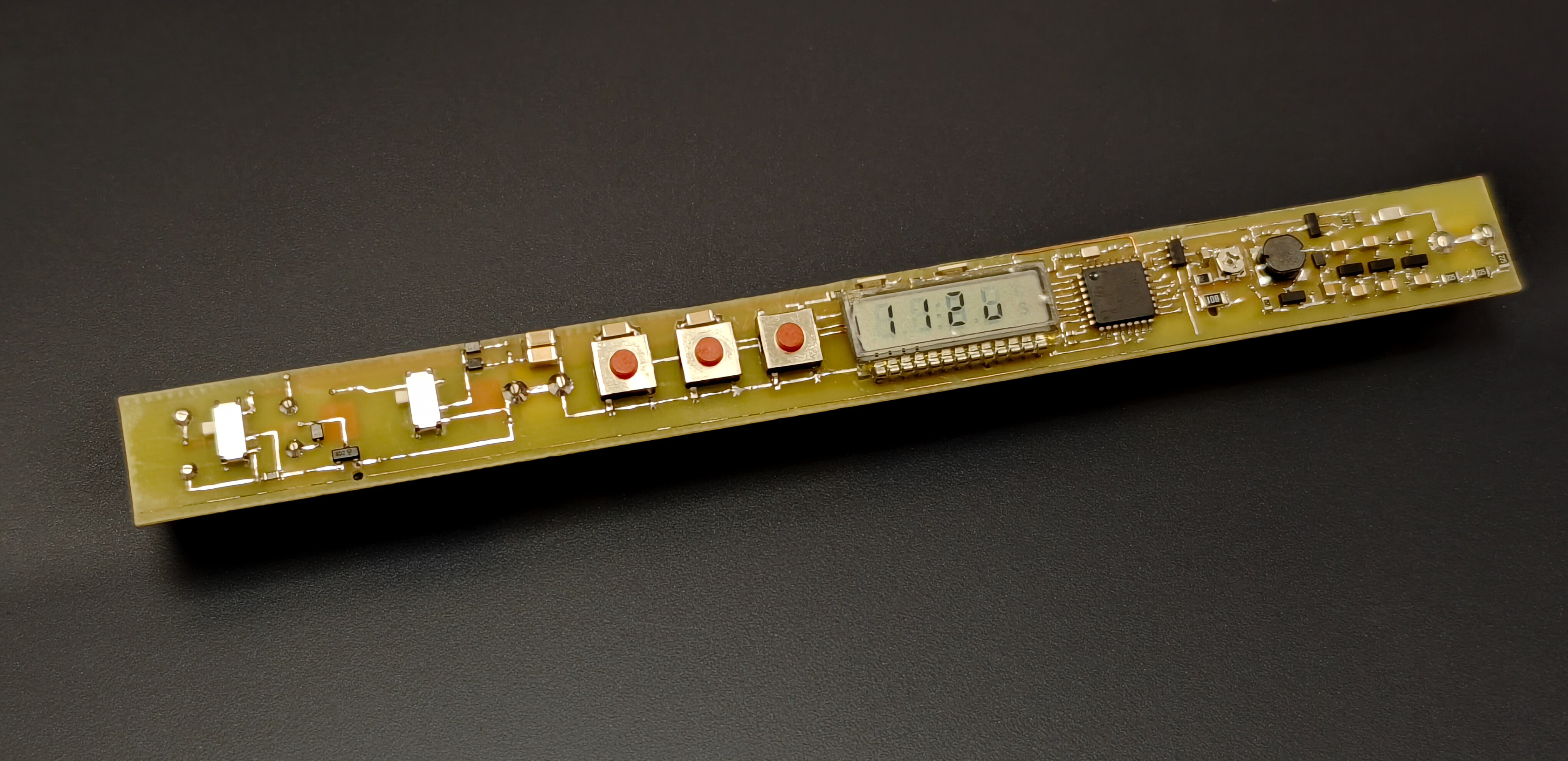
Compact, low-power Geiger counter
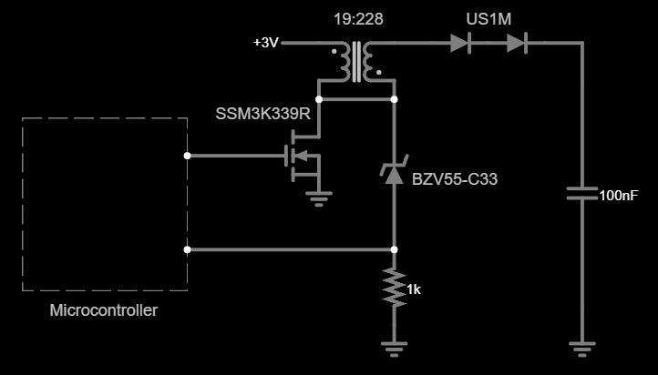
A marker pen sized Geiger counter with up to 12 months battery life from 2xLR44, based on STM8L152K4 microcontroller
 BleakyTex
Become a Hackaday.io member
Already have an account? Log in.
Just one more thing
To make the experience fit your profile, pick a username and tell us what interests you.
Pick an awesome username
hackaday.io/
Your profile's URL: hackaday.io/username. Max 25 alphanumeric characters.
Pick a few interests
Projects that share your interests
People that share your interests


 jaromir.sukuba
 Paul Andrews
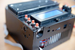
 Radu Motisan
 James Wilson
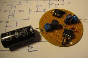
Congrats for the super impressive project! I love your detailed logs -- so much so that I shamelessly stole your previous boost design for half of my SiPM bias generator. Thanks!