ElectroBoy
Relays are the most useful and stable AC power switching components. Relays provide complete isolation of DC operating voltage from AC mains. The regular size of relays is big because of mechanical moving actuator and a coil. The coil forms an electromagnet which then used to attract the metal actuator points and thus turn on the AC power. The most popular relay SPDT (single pole double throw) has 5 terminals, 2 for the coil and 3 for the mains connections. NO (Normally open), NC (Normally closed) and COM (common point).
The main problem is that the takes a lot of current and due to mechanical action of actuators there is sparks in between of both terminals. Which cause serious problems like tear down, terminal welding and damaging. But there is one solution to all of these problems known as SSR (solid state relays). They are the electronic based switches which can be used for fast switching of AC appliances or to control the power ratings.
These electronic AC switches are known as TRIAC. In last we will build our own SSR module using 4 TRIAC and compare the same with the existing mechanical relays. I am using JLCPCB SMT assembly service, JLCPCB is the China’s leading PCB manufacturing company working in this field for more than 15 years. You can explore the all services from here. Sign-up using this link to JLCPCB and get $54 new user coupons for the next order.
TRIAC v/s SCR:
A TRIAC (triode for alternating current; also bidirectional triode thyristor is a three terminal electronic component that conducts current in either direction when triggered.
TRIACs are a subset of thyristors (analogous to a relay in that a small voltage and current can control a much larger voltage and current) and are related to silicon controlled rectifiers (SCRs). TRIACs differ from SCRs in that they allow current flow in both directions, whereas an SCR can only conduct current in a single direction. Most TRIACs can be triggered by applying either a positive or negative voltage to the gate (an SCR requires a positive voltage). Once triggered, SCRs and TRIACs continue to conduct, even if the gate current ceases, until the main current drops below a certain level called the holding current.
The bidirectionality of TRIACs makes them convenient switches for alternating-current (AC). In addition, applying a trigger at a controlled phase angle of the AC in the main circuit allows control of the average current flowing into a load (phase control). This is commonly used for controlling the speed of a universal motor, dimming lamps, and controlling electric heaters. TRIACs are Bipolar devices.
Switching modes of TRIAC and Driver:
As stated above “Once triggered, SCRs and TRIACs continue to conduct, even if the gate current ceases, until the main current drops below a certain level called the holding current”. But here in our case we are using a dedicated TRIAC driver, this one helps in switching the TRIAC by AC cycle feedback. There are two types of TRIAC driver available in market one is Zero voltage switching and other one is random phase shift. You can see all info in the video given above about these drivers.
Components Required:
1) BT136 (SMT package)
2) MOC3021 (TRIAC driver)
3) 10k, 1k Resistor
4) Pin headers and screw terminals
5) PCB prototypes from JLCPCB
Circuit Diagram:
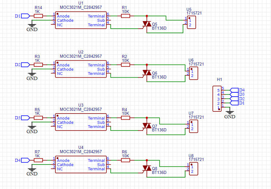
The circuit has a DIAC based optocoupler known as TRIAC driver, which has a LED, DIAC inside and triggered with help of DC voltage to the LED terminal. This provides fully insulation of supply to the mains voltage. DIAC has two terminals one is connected to the GATE pin of BT136 and other one is the AC mains with a 10k resistor. This circuit is the most practical one for the microcontrollers. But you can also change the driver form Zero volt switching to the Random phase in order to controller the supplied power to the load.
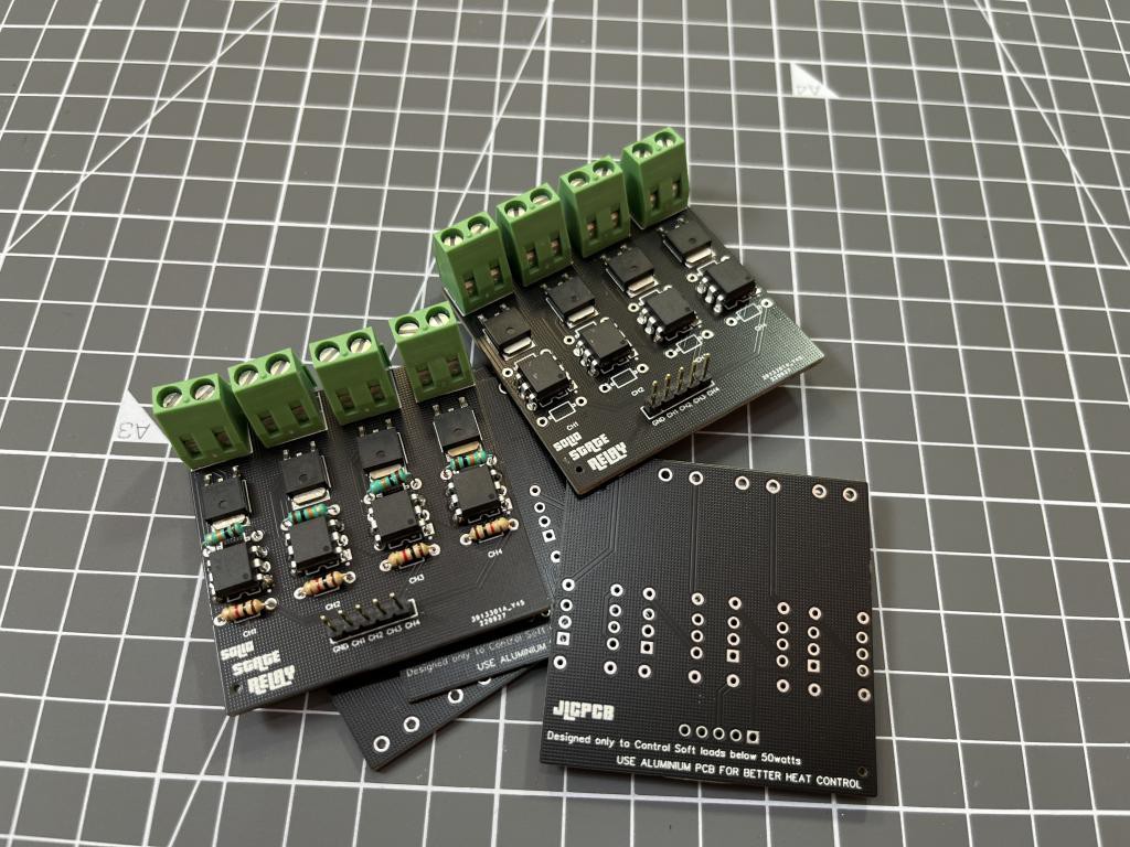
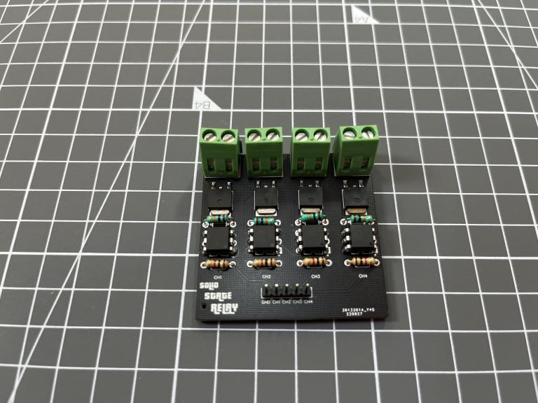
PCB soldering and components placement:
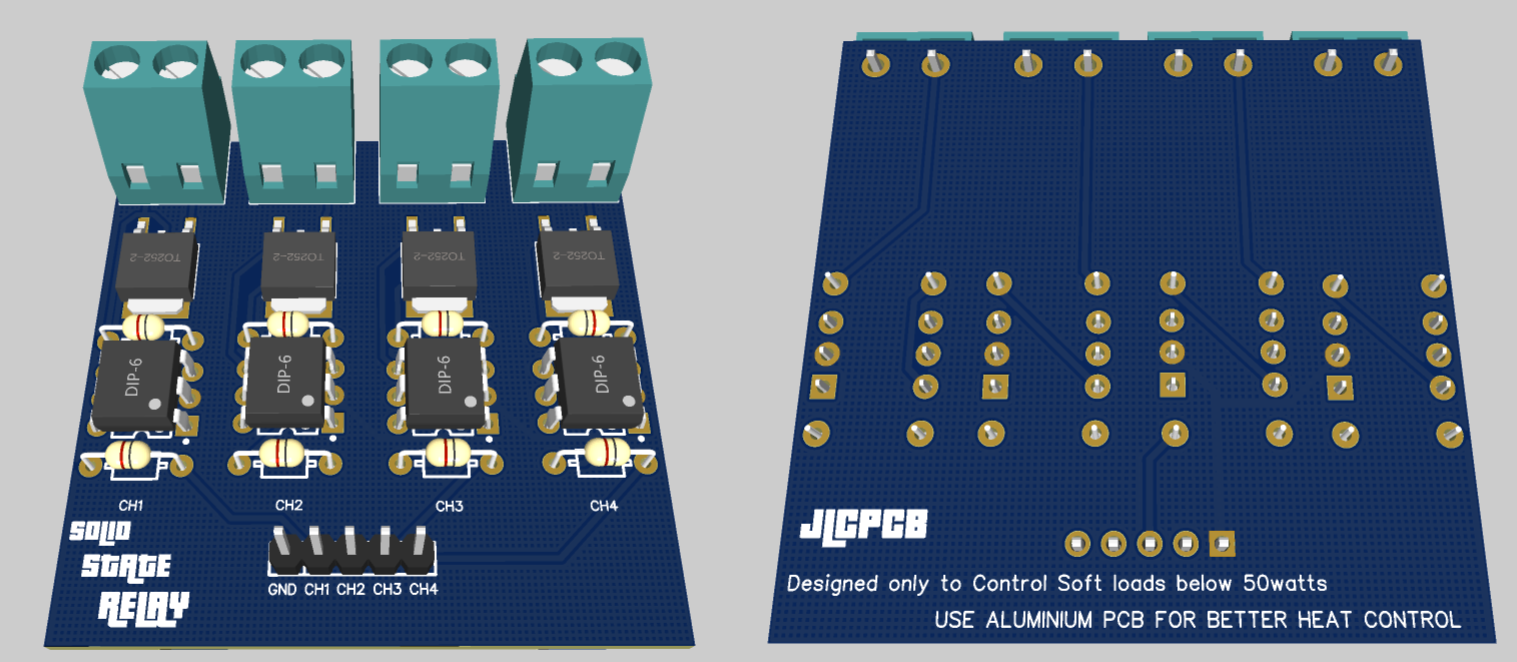
I used SMT assembly service from JLCPCB, because I want to make the PCB clean...
Read more »
 adria.junyent-ferre
 Sagar 001
 mbsg99