 Sagar 001
Inverters are widely used devices in electronics and electrical circuits. An inverter converts corresponding DC voltage into AC. We are very familiar with linear dc power supplies, which is used to convert 220v Ac into low voltage high ampere DC. In the same way, A high ampere battery or supply is required to step up voltage to required value. Transformers are very helpful in all of these cases. Induced EMF is based on number of turns and wire gauge.
Note** High voltage/ Square wave on high AC/ Circuit can handle 100w maximum with this driver stage. Overheating may occur if there is any further push in power limits.
To power up the load safely, we will make a PCB design and order it from best PCB manufacturer JLCPCB. You can order 5pcs of high quality 2-layer PCB in just $2. JLCPCB is one stop solution for all of my projects providing 3D printing, Stencil and SMT assembly service along with simple pcb prototypes in best prices. So, order you PCB now from JLCPCB and get free coupons on first sign-up.
Type of Transformer required:

Step-down transformer is used to convert high voltage AC into DC. AC is supplied to the primary winding has a greater number of turns as compared to secondary and thus induced emf generate voltage in secondary winding. In the same way if we reverse the procedure, it can generate high voltage. For small loads (less than 100W) these transformers are great but we need more powerful and dedicated center tapped transformer. Which will cost more and need heavy driver circuitry with separate microcontroller unit. To get more grip on the topic of transformer follow this article here.
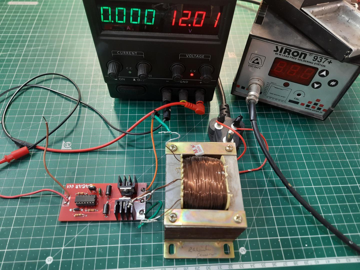
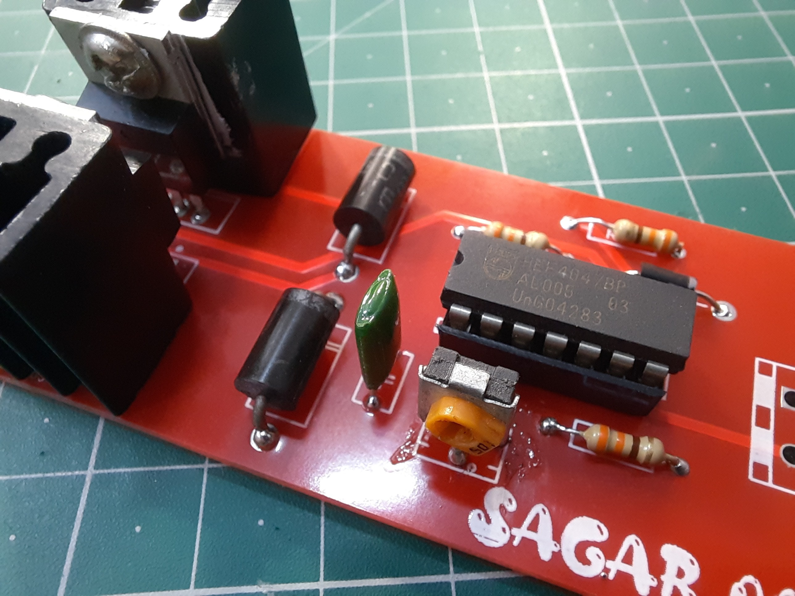
In this project, we are using Centre tapped Step down 12-0-12volt Iron core transformer as voltage booster.
IC CD4047:

CD4047 is a 14-pin IC, It is a low-power CMOS logic-based multivibrator circuit IC. It can operate in the monostable mode or astable mode. This IC is easy to use for both modes and requires fewer external components to operate. It has a voltage range of 3V-15V and works best at 5V DC supply.

The answer is that We have to drive the gates of MOSFET. So this task is done by CD4047 by generating square wave or PWM. Most of the power inverter uses this technique to drive the MOSFETs or transistors.
Components required:

1) CD4047 IC
2) IRF Z44N MOSFET with heatsink
3) 1nF capacitor
4) 100K-1M potentiometer
5) 330ohms resistor
6) 1N4007 Diode
7) 12v battery
9) Centre Tapped Transformer(12-0-12)
10) Wires and soldering tools.
Circuit Diagram:
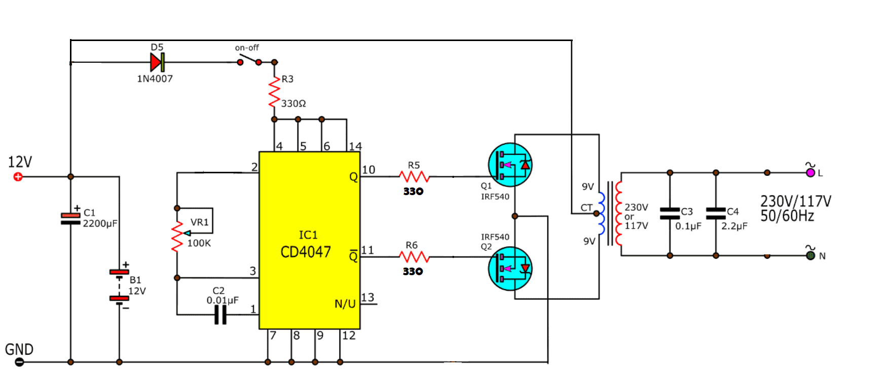
The circuit is simple, IC CD4047 drives the two MOSFETs which are in push-pull configuration. As, the usual transformer cannot work on DC, so we have to make voltage and current changing circuit w.r.t time. So, the flux will induce in the core which will induce a voltage on the secondary winding. You can adjust the potentiometer to get the desired frequency. Usually, the frequency is 50 or 60 Hz. The rating of the transformer should be enough to bear the output power.
Battery should be greater than 10Ah so that battery voltage should not drop, and it should work for a long time. The LED here indicates that the power inverter is ON. So, whenever it is ON, don’t touch the inverter otherwise you will get harmed.
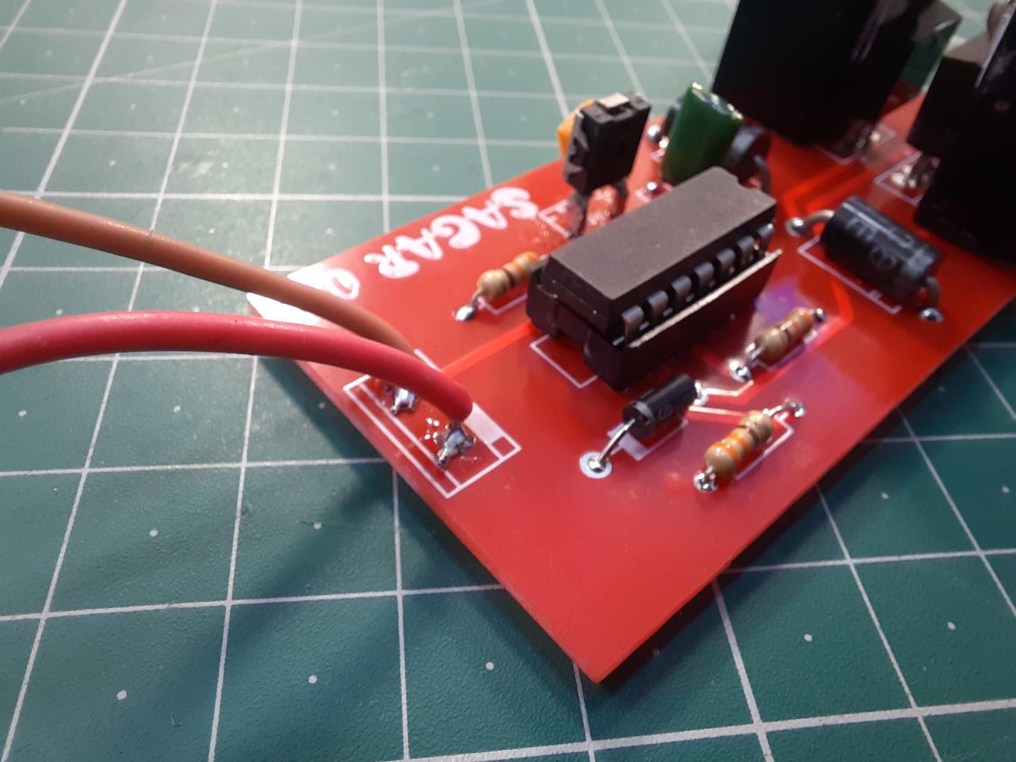
PCB designs:
Download Gerber files and Circuit schematics from here.
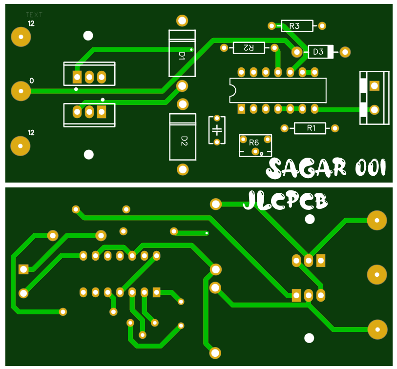
I order 5pcs. of 2-layer Red colored PCB in just $2. With Hasl finish and 1.6mm thickness. JLCPCB is the only solution to get your prototype PCB in best prices. And if you Sign-Up using this link, you will get free coupon of $30 and new user gifts. Checkout to JLCPCB and turn your projects into products.
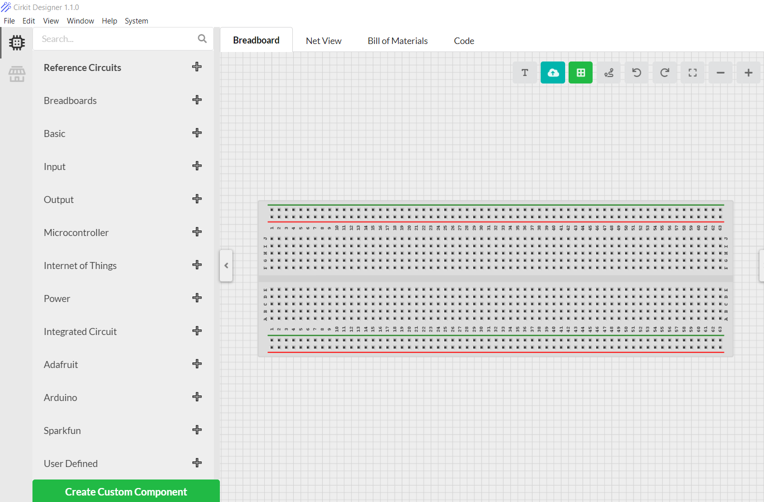
I am using Cirkit designer software for a long time, this is one stop solution to all of my projects with arduino. You can design breadboard schematics, wire diagrams. Now coming with BOM, custom component creating option and inbuilt code compilation option. Try...
Read more »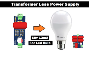
 Lithium ION
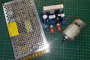
 w_k_fay
 Discrete Electronics Guy